
BOSCH REXROTH
0811405157
All Other Products
BOSCH REXROTH
MATERIAL: 0811405157
SUMMARY:
Due to extremely high demand, please call 888-651-5712 for availability
|
01 |
02 |
03 |
04 |
05 |
06 |
07 |
08 |
09 |
10 |
|||||
|
VT |
– |
V |
A |
C |
A |
P |
– |
500 |
– |
2X |
/ |
V0 |
/ |
|
01 |
VT |
|
|
02 |
V |
|
|
Hydraulic component (control) |
||
|
03 |
Axis control |
A |
|
Valve type |
||
|
04 |
High-response valve |
C |
|
Control |
||
|
05 |
Analog |
A |
|
Function |
||
|
06 |
p/Q control |
P |
|
Serial number for types |
||
|
07 |
Standard variant without valve amplifier function |
500 |
|
08 |
Component series 20 ... 29 (20 ... 29: unchanged technical data and pin assignment) |
2X |
|
Customer version |
||
|
09 |
Catalog version |
V0 |
|
Option |
||
|
10 |
1 channel |
no code |
|
2 channels |
2CH |
|
General
|
Type / version |
VT-VACAP-500-20/V0 | VT-VACAP-500-20/V0/2CH | ||
|
Supply voltage |
nominal 24 V= battery voltage 21...40 V, rectified alternating voltage Ueff = 21...28 V (single-phase, full-wave rectifier) |
|||
|
Smoothing capacitor, separately |
Recommendation: Capacitor module VT 11110 (see data sheet 30750) (only necessary if the ripple of UB >10 %) |
|||
|
Current consumption, max. |
0811405157 |
mA |
160 | |
|
0811405158 |
mA |
220 | ||
| Basic card | Daughter card | |||
|
Pressure sensor (1…6 V/0…10 V) |
b26 – ref. b28 | b16 – ref. b18 | ||
|
Pressure sensor (4…20 mA) |
b24 – ref. b28 | z14 – ref. b18 | ||
|
Pressure sensor supply ‒ V |
z6 (+15 V)/b8 (0 V) | |||
|
Pressure command value (0…10 V) |
b12/b14 (0 V) | z12/z10 (0 V) | ||
|
External controller shut-off |
z28: 6...40 V= | b10: 6...40 V= | ||
|
External controller enquiry |
z26: 24 V=, max. 20 mA | z24: 24 V=, max. 20 mA | ||
|
Monitor signal pactual |
z16: 0...10 V= | z18: 0...10 V= | ||
|
External channel change mode |
z30: 6...40 V= | |||
|
Flow command value |
z22: 0...±10 V= b22: 0 V |
z20: 0...±10 V= b22: 0 V |
||
|
Potentiometer supply |
z32: +10 V, max. 10 mA | |||
|
Outlet |
UAI; b4/b8 (0 V): 0...±10 V Last RL > 1 kΩ |
UAII; b6/b8 (0 V): 0...±10 V Last RL > 1 kΩ |
||
|
Cable |
Pressure sensor |
4 x 0.5 mm2 (shielded) | ||
|
Valve |
5 x 0,5 mm2 | |||
|
PLC signals |
0.5 mm2 (shielded) | |||
|
LED displays/channel |
Pressure controller OFF Controller working Pressure sensor cable break (both LEDs are flashing) |
|||
|
Special features |
Cable break monitoring for pressure sensors Test points for important characteristics External pressure controller shut-off External channel change mode Different pressure sensors possible |
|||
|
Plug-in connection |
Plug to DIN 41612-F32 | |||
|
Operating temperature |
°C |
0 … +70 | ||
|
Storage temperature range |
°C |
-20 … +70 | ||
|
Weight |
m |
kg |
0.35 | |
For applications outside these parameters, please consult us!
a |
||
b |
Problem: P share too small Solution: → Rotate Kp against F (fine adjustment) → P gain > |
|
|
DIL 14 |
ON |
|
|
DIL 15 |
OFF |
|
|
DIL 16 |
ON |
|
c |
Problem: P share too large Solution: → Rotate Kp against 0 (fine adjustment) → Use DIL 14–16 to reduce the P gain according to the table |
|
d |
Problem: P share correct Control deviation too large Solution: ➝ Increase the I gain share DIL 11 ON = I share = 0 DIL 12 ON = I share connected → Rotate Ki against F |
|
e |
Problem: Time constant of the I share too low Solution: → Rotate Ki against F until control deviation and vibration are perfect → If Ki = F is not sufficient, the P share must also be reduced |
|
f |
Problem: D share too low Solution: → Rotate KD against F → D share > |
|
|
DIL 8 |
ON |
|
|
DIL 9 |
OFF |
|
|
DIL 10 |
OFF |
|
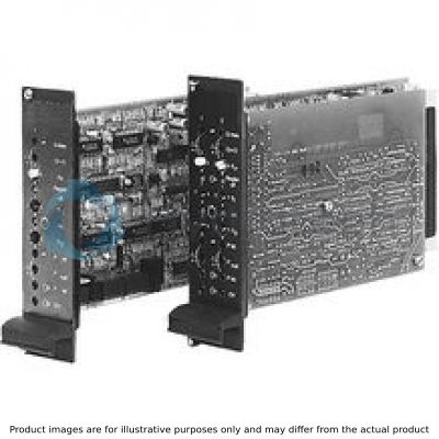
Front plate

Block diagram with pin assignment

Amplifier – Valve

Pressure sensor connection: Example channel II

Principle of the channel selection

Adjustment table

DIL switch

HEXCODE switch

Example 2
Channel mode "separate outputs"

Example 1
Channel mode "joint output"

Dimensions in mm
