
BOSCH REXROTH
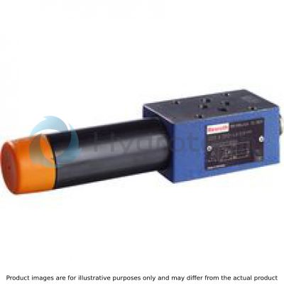
ZDZ6DP2-4X/75YM
R900519968
Pressure Sequence Valves
Pressure valves: ZDZ 6.-4x/
BOSCH REXROTH
MATERIAL: R900519968
SUMMARY: Pressure valves: ZDZ 6.-4x/
Quantity in stock: 0
Valve type ZDZ is a direct operated pressure sequence valve in sandwich plate design. It is used for the pressure-dependent connection of a second system. The sequencing pressure is set via the adjustment type (4).
Version "P"
The compression spring (3) holds the control spool (2) in the initial position – the valve is blocked. The pressure in channel P➁ is applied via the control line (5) at the spool face of the control spool (2) opposite the compression spring (3).
If channel P➁ reaches the set value of the compression spring (3), the control spool (2) is moved to the left and the connection from P➁ to P➀ is opened. The system connected to channel P➀ is connected without a pressure drop in channel P➁.
The pilot oil return from the spring chamber (7) is always realized externally via the bore (6) to channel T (Y).
A pressure gauge connection (8) enables control of the sequencing pressure at the valve.
Version "A"
Here, pressure sequencing is realized in channel A. Control signal and pilot fluid are supplied internally from channel A➀.
A check valve can be optionally installed for free hydraulic fluid return flow from A➁ to A➀.
Type ZDZ 6 DP1–4X/…YM…

Type ZDZ 6 DA1–4X/…YM

|
➀ |
component side |
|
➁ |
plate side |
|
01 |
02 |
03 |
04 |
05 |
06 |
07 |
08 |
09 |
10 |
11 |
12 |
13 |
||
|
Z |
DZ |
6 |
D |
– |
4X |
/ |
Y |
* |
|
01 |
Sandwich plate valve |
Z |
|
02 |
Sequence valve |
DZ |
|
03 |
Size 6 |
6 |
|
04 |
Direct operated |
D |
|
05 |
Pressure limitation in channel P➀ |
P |
|
Pressure limitation in channel A➁ |
A |
|
|
Adjustment type |
||
|
06 |
Rotary knob |
1 |
|
Grub screw with hexagon and protective cap |
2 |
|
|
Lockable rotary knob with scale 1) |
3 |
|
|
Rotary knob with scale |
7 |
|
|
07 |
Component series 40 … 49 (40 … 49: unchanged installation and mounting dimensions) |
4X |
|
Pressure rating |
||
|
08 |
Maximum sequencing pressure 25 bar |
25 |
|
Maximum sequencing pressure 75 bar |
75 |
|
|
Maximum sequencing pressure 150 bar |
150 |
|
|
Maximum sequencing pressure 210 bar |
210 |
|
|
09 |
Internal pilot oil supply, external pilot oil return |
Y |
|
10 |
With check valve 2) |
no code |
|
Without check valve |
M 3) |
|
|
Seal material |
||
|
11 |
NBR seals |
no code |
|
FKM seals |
V |
|
|
Observe compatibility of seals with hydraulic fluid used. |
||
|
12 |
Without locating hole |
no code |
|
With locating hole |
/60 4) |
|
|
13 |
Further details in the plain text |
* |
| 1) | H-Key with material no. R900008158 is included in the scope of delivery. |
| 2) | Only version "A" |
| 3) | Locking pin ISO 8752-3x8-St, material no. R900005694 (separate order) |
general
|
Size |
6 | ||
|
Weight (approx.) |
kg |
1.2 | |
|
Installation position |
any | ||
|
Ambient temperature range |
NBR seals |
°C |
-30 … +80 |
|
FKM seals |
°C |
-20 … +80 | |
hydraulic
|
Size |
6 | ||
|
Maximum operating pressure |
Port P |
bar |
210 |
|
Anschluss A |
bar |
210 | |
|
Port B |
bar |
210 | |
|
Port T (Y) |
bar |
160 | |
|
Maximum sequencing pressure |
bar |
25 75 150 210 |
|
|
Maximum flow |
l/min |
60 | |
|
Hydraulic fluid |
see table | ||
|
Hydraulic fluid temperature range |
NBR seals |
°C |
-30 … +80 |
|
FKM seals |
°C |
-20 … +80 | |
|
Viscosity range |
mm²/s |
10 … 800 | |
|
Maximum admissible degree of contamination of the hydraulic fluid 1) |
Class 20/18/15 according to ISO 4406 (c) | ||
| 1) | The cleanliness classes specified for the components must be adhered to in hydraulic systems. Effective filtration prevents faults and simultaneously increases the life cycle of the components. For the selection of the filters, see www.boschrexroth.com/filter. |
|
Hydraulic fluid |
Classification |
Suitable sealing materials |
Standards |
Data sheet |
|
|
Mineral oils |
HL, HLP, HLPD |
NBR, FKM |
DIN 51524 |
90220 |
|
|
Bio-degradable |
Insoluble in water |
HETG |
FKM |
ISO 15380 |
90221 |
|
HEES |
FKM |
||||
|
Soluble in water |
HEPG |
FKM |
ISO 15380 |
||
|
Flame-resistant |
Water-free |
HFDU (glycol base) |
FKM |
ISO 12922 |
90222 |
|
HFDU (ester base) |
FKM |
||||
|
HFDR |
FKM |
||||
|
Containing water |
HFC (Fuchs Hydrotherm 46M, Petrofer Ultra Safe 620) |
NBR |
ISO 12922 |
90223 |
|
|
Important information on hydraulic fluids: For further information and data on the use of other hydraulic fluids, please refer to the data sheets above or contact us. There may be limitations regarding the technical valve data (temperature, pressure range, life cycle, maintenance intervals, etc.). The ignition temperature of the hydraulic fluid used must be 50 K higher than the maximum surface temperature. Flame-resistant – containing water: Maximum pressure differential 210 bar, otherwise, increased cavitation erosion Life cycle as compared to operation with mineral oil HL, HLP 30 … 100% Maximum hydraulic fluid temperature 60 °C Bio-degradable and flame-resistant: If this hydraulic fluid is used, small amounts of dissolved zinc may get into the hydraulic system. |
|||||
For applications outside these parameters, please consult us!
(measured with HLP46, ϑOil = 40 ±5 °C)
Δp-qV characteristic curves
Version "P"

Δp-qV characteristic curves
Version "A"

p-qV characteristic curves
Version "P"

p-qV characteristic curves
Version "A"

|
1 |
P➀ to P➁ |
|
2 |
A➀ to A➁ |
|
3 |
A➁ to A①; flow only via check valve |
Notes:
The characteristic curves apply to the pressure at the valve output pT = 0 bar across the entire flow range.
Version "A...Y"

Version "A...YM"

Version "P...YM"

Version "P"
Dimensions in mm

 |
|
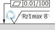
Required surface quality of the valve contact surface |
|
➀ |
component side – porting pattern according to ISO 4401-03-02-0-05 (with or without locating hole); (with locating hole Ø4 x 4 mm deep) |
|
➁ |
plate side – Porting pattern according to ISO 4401-03-02-0-05 (with or without locating hole); (with locating hole Ø3 x 5 mm deep for locking pin ISO 8752-3x8-St, material no. R900005694, separate order) |
|
1 |
Name plate |
|
2 |
Adjustment type "1" |
|
3 |
Adjustment type "2" |
|
4 |
Adjustment type "3" |
|
5 |
Adjustment type "7" |
|
6 |
Dimensions required to remove the key |
|
7 |
Valve mounting bores |
|
8 |
Lock nut SW24 |
|
9 |
Hexagon SW10 |
|
10 |
Identical seal rings for ports A➁, B➁, P➁, T➁(Y) |
|
11 |
Pressure gauge connection G1/4; 12 mm deep; internal hexagon SW6 |
Valve mounting screws (separate order)
4 hexagon socket head cap screws ISO 4762 - M5 - 10.9
Notes:
Length and tightening torque of the valve mounting screws must be calculated according to the components mounted under and over the sandwich plate valve. The dimensions are nominal dimensions which are subject to tolerances.Version "A"
Dimensions in mm

|
|
|
Required surface quality of the valve contact surface |
|
➀ |
component side – porting pattern according to ISO 4401-03-02-0-05 (with or without locating hole); (with locating hole Ø4 x 4 mm deep) |
|
➁ |
plate side – Porting pattern according to ISO 4401-03-02-0-05 (with or without locating hole); (with locating hole Ø3 x 5 mm deep for locking pin ISO 8752-3x8-St, material no. R900005694, separate order) |
|
1 |
Name plate |
|
2 |
Adjustment type "1" |
|
3 |
Adjustment type "2" |
|
4 |
Adjustment type "3" |
|
5 |
Adjustment type "7" |
|
6 |
Dimensions required to remove the key |
|
7 |
Valve mounting bores |
|
8 |
Lock nut SW24 |
|
9 |
Hexagon SW10 |
|
10 |
Identical seal rings for ports A➁, B➁, P➁, T➁(Y) |
|
11 |
Pressure gauge connection G1/4; 12 mm deep; internal hexagon SW6 |
Valve mounting screws (separate order)
4 hexagon socket head cap screws ISO 4762 - M5 - 10.9
Notes:
Length and tightening torque of the valve mounting screws must be calculated according to the components mounted under and over the sandwich plate valve. The dimensions are nominal dimensions which are subject to tolerances.