
BOSCH REXROTH
ZSFW50F1-1-1X/M/01
R900535175
Prefill Valves
Check valves: ZSF,ZSFW 50.-1x/
BOSCH REXROTH
MATERIAL: R900535175
SUMMARY: Check valves: ZSF,ZSFW 50.-1x/
Quantity in stock: 0
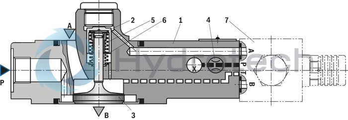
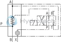
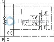
Type ZSFW… (NG32 … 160)
Without pre-decompression and built-on directional valve, vertical working direction of the control spool
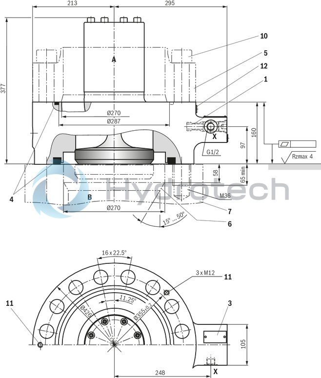
Type ZSFW… (NG200)
Without pre-decompression and built-on directional valve, vertical working direction of the control spool

|
7 |
Directional valve type 4WE 6 D (separate order) |
|
01 |
02 |
03 |
04 |
05 |
06 |
07 |
08 |
09 |
10 |
11 |
||||
|
ZSF |
W |
F |
0 |
– |
1 |
– |
/ |
M |
/ |
01 |
* |
|
01 |
Prefill valve, sandwich plate design |
ZSF |
|
02 |
For directional valve set-up |
W |
|
Size |
||
|
03 |
Size 32 |
32 |
|
Size 40 |
40 |
|
|
Size 50 |
50 |
|
|
Size 63 |
63 |
|
|
Size 80 |
80 |
|
|
Size 100 |
100 |
|
|
Size 125 |
125 |
|
|
Size 160 |
160 |
|
|
Size 200 |
200 |
|
|
04 |
Flange connection |
F |
|
05 |
Without pre-decompression (With pre-decompression on request) |
0 |
|
Cracking pressure main poppet |
||
|
06 |
pÖ ≈ 0,12 bar |
1 |
|
07 |
(NG32 … 100 and NG160) Component series 10 ... 19 (10 ... 19: unchanged installation and connection dimensions) |
1X |
|
Component series 20 ... 29 (20 ... 29: unchanged installation and connection dimensions) (Size 125 1) and 200) |
2X |
|
|
Seal material |
||
|
08 |
NBR seals |
M |
|
FKM seals |
V |
|
|
Observe compatibility of seals with hydraulic fluid used. |
||
|
Connection version |
||
|
09 |
Mounting cavities with pipe thread according to ISO 228, DIN EN 3852-part 2 |
01 |
|
Pipe thread “UNF/UN” according to ANSI/ASME B 1.1 |
12 |
|
|
Nozzle bore |
||
|
10 |
NG32 … 160 – nozzle in channel P installed at the factory no code |
no code |
|
NG200 – nozzle in channel P installed at the factory |
D40 |
|
|
11 |
Further details in the plain text |
* |
1) Compatible with series 1X
general
|
Size |
32 | 40 | 50 | 63 | 80 | 100 | 125 | 160 | 200 | |
|
Weight |
kg |
3.5 | 4.2 | 5.5 | 7 | 10 | 15 | 26 | 47 | 150 |
|
Installation position 1) |
any | |||||||||
|
Ambient temperature range 2) |
°C |
-30 … +80 | ||||||||
|
Porting pattern |
ISO 4401-03-02-0-05 | |||||||||
| 1) | Working direction of the control spool |
| 2) | Observe the technical data of the directional valve, see type 4WE 6 D... or type M-.SEW 6... |
hydraulic
|
Size |
32 | 40 | 50 | 63 | 80 | 100 | 125 | 160 | 200 | ||
|
Maximum operating pressure |
Port P 1) |
bar |
350 | ||||||||
|
Anschluss A |
bar |
16 | |||||||||
|
Port B |
bar |
350 | |||||||||
|
Anschluss X |
bar |
150 | |||||||||
|
Cracking pressure 2) |
bar |
≈ 0.12 | |||||||||
|
Druckflüssigkeit |
see table | ||||||||||
|
Hydraulic fluid temperature range |
°C |
-30 … +70 | |||||||||
|
Viscosity range |
mm²/s |
10 … 800 | |||||||||
|
Maximum admissible degree of contamination of the hydraulic fluid 3) |
Class 20/18/15 according to ISO 4406 (c) | ||||||||||
|
Technical data of the directional valve |
Directional spool valve |
see type 4WE 6 D... | |||||||||
|
Directional seat valve |
see type M-.SEW 6... | ||||||||||
| 1) | Observe the technical data of the directional valve, see type 4WE 6 D... or type M-.SEW 6... |
| 2) | Pressure differential at the main poppet for overcoming the spring force |
| 3) | The cleanliness classes specified for the components must be adhered to in hydraulic systems. Effective filtration prevents faults and simultaneously increases the life cycle of the components. For the selection of the filters, see www.boschrexroth.com/filter. |
|
Hydraulic fluid |
Classification |
Suitable sealing materials |
Standards |
Data sheet |
|
|
Mineral oils |
HL, HLP, HLPD, HVLP, HVLPD |
NBR, FKM |
DIN 51524 |
90220 |
|
|
Bio-degradable |
Insoluble in water |
HETG |
FKM |
ISO 15380 |
90221 |
|
HEES |
FKM |
||||
|
Soluble in water |
HEPG |
FKM |
ISO 15380 |
||
|
Flame-resistant |
Water-free |
HFDU (glycol base) |
FKM |
ISO 12922 |
90222 |
|
HFDU (ester base) |
FKM |
||||
|
HFDR |
FKM |
||||
|
Containing water |
HFC (Fuchs Hydrotherm 46M, Petrofer Ultra Safe 620) |
NBR |
ISO 12922 |
90223 |
|
|
Important information on hydraulic fluids: For further information and data on the use of other hydraulic fluids, please refer to the data sheets above or contact us. There may be limitations regarding the technical valve data (temperature, pressure range, life cycle, maintenance intervals, etc.). The ignition temperature of the hydraulic fluid used must be 50 K higher than the maximum surface temperature. Flame-resistant – containing water: Maximum pressure differential 210 bar, otherwise, increased cavitation erosion Life cycle as compared to operation with mineral oil HL, HLP 30 … 100% Maximum hydraulic fluid temperature 60 °C Bio-degradable and flame-resistant: If this hydraulic fluid is used, small amounts of dissolved zinc may get into the hydraulic system. |
|||||
Flow qV in l/min (A to B) for different cases of application (Δp = 0,3 bar)
|
Size |
32 | 40 | 50 | 63 | 80 | 100 | 125 | 160 | 200 | |
|
Case of application 1 |
l/min |
200 | 300 | 500 | 800 | 1200 | 1900 | 3000 | 4200 | 7000 |
|
Case of application 2 |
l/min |
170 | 250 | 400 | 650 | 1000 | 1600 | 2600 | 3900 | 6510 |
|
Case of application 3 |
l/min |
140 | 220 | 360 | 560 | 900 | 1400 | 2200 | 3400 | 5670 |
|
Case of application 4 |
l/min |
100 | 150 | 240 | 380 | 620 | 950 | 1500 | 2300 | 3850 |
|
Case of application 5 |
l/min |
70 | 110 | 170 | 280 | 450 | 700 | 1100 | 1690 | 2800 |
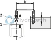
Case of application 1
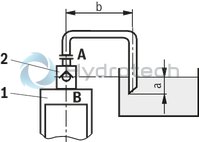
Case of application 2
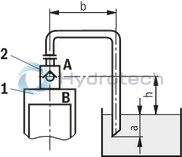
Case of application 3
Size of the filling tank at least 1.5 x cylinder content
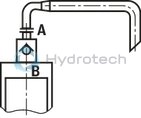
Case of application 4
Case of application 5
Information on case of application 2 to 5
For limit areas, please contact us. It is often enough, to select a pipeline which is one size larger.
Note:
Wrong dimensioning of prefill valve and suction line may cause cavitation and consequential damage.
|
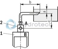
1 |
Cylinders |
|
2 |
Prefill valve |
|
3 |
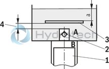
This sheet is not included in the scope of delivery. With smaller tank dimensions and minimum hydraulic fluid level (a), it prevents the formation of tunnels. |
|
4 |
Observe the supply cross-section |
|
a |
at least 300 mm with extended cylinder |
|
b |
up to 1000 mm with the specified maximum flows |
|
c |
h ≤ 500 mm |
|
h |
300 mm ≤ h < 500 mm |
For applications outside these parameters, please consult us!
(measured with HLP46, ϑOil = 40 ±5 °C)
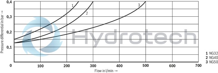
Size 32, 40, and 50
Pressure differential Δp between ports A and B dependent on the flow qV (A to B).
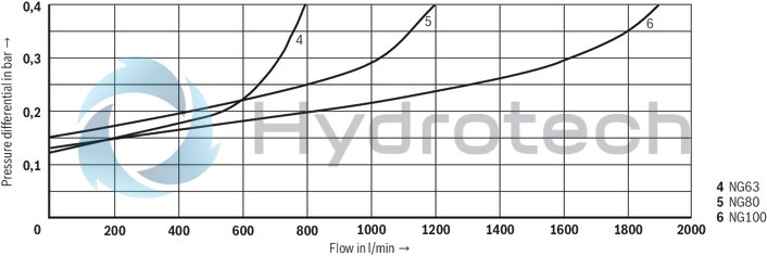
Size 63, 80 and 100
Pressure differential Δp between ports A and B dependent on the flow qV (A to B).
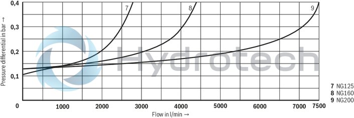
Size 125, 160, and 200
Pressure differential Δp between ports A and B dependent on the flow qV (A to B).
NG32 … 160 (With high-pressure connection)
Nozzle in channel P installed at the factory
NG200 (Without high-pressure connection)
Nozzle in channel P installed at the factory
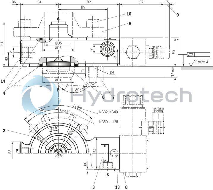
NG32 … 125
Dimensions in mm
 |
|
Required surface quality of the valve contact surface |
|
2 |
Centering diameter |
|
3 |
Name plate |
|
4 |
Seal rings |
|
5 |
Counterflange (separate order, see "dimensional proposal for counterflange") |
|
6 |
Stroke of main poppet (see "Poppet geometry and determination of the minimum pilot pressure") |
|
7 |
Note: Valve contact face (e.g. pressing cylinders, bearing structures, etc.) must be sufficiently rigid. The prefill valve must not be loaded by bending. |
|
9 |
Space required to remove the mating connector |
|
10 |
Valve mounting screws (separate order) |
|
13 |
Damping nozzle M8 x 1 |
|
14 |
Additional pressure port; if not used, seal in a hydraulically tight way by means of suitable plug screws. |
|
NG |
B1 |
B2 |
B3 |
B4 |
B5 |
B6 |
ØD1 |
ØD2 |
ØD3 |
D4 |
ØD5 |
ØD6 |
H1 |
H2 |
H3 |
H4 |
P |
T1 |
T2 |
X |
|
|
mm |
mm |
mm |
mm |
mm |
max. mm |
mm |
mm |
mm |
mm |
mm |
mm |
mm |
mm |
mm |
mm |
mm |
min. mm |
||||
| 32 | 65 | 107 | 40 | 55 | 85 | 1.5 | 46 | 93 | 110 | ± 0.2 | M16 | 42 | 49.5 | 77 | 50 | 26.5 | 34 | G1/2 | 8 | 30 | G1/4 |
| 40 | 70 | 112 | 40 | 55 | 90 | 1.5 | 58 | 108 | 125 | ± 0.2 | M16 | 52 | 61.5 | 80 | 50 | 26.5 | 34 | G1/2 | 10 | 35 | G1/4 |
| 50 | 110 | 137 | 40 | 55 | 115 | 1.5 | 71 | 128 | 145 | ± 0.2 | M16 | 70 | 75.7 | 97 | 50 | 26.5 | 34 | G1/2 | 12 | 30 | G1/4 |
| 63 | 115 | 142 | 45 | 55 | 120 | 1.5 | 90 | 143 | 160 | ± 0.2 | M16 | 83 | 97.7 | 110 | 55 | 27.5 | 34.5 | G3/4 | 14 | 35 | G1/4 |
| 80 | 125 | 157 | 45 | 55 | 135 | 1.5 | 107 | 169 | 190 | ± 0.2 | M20 | 100 | 112 | 123 | 60 | 30 | 37.5 | G3/4 | 16 | 30 | G1/4 |
| 100 | 140 | 186 | 55 | 55 | 165 | 1.5 | 132 | 212 | 240 | ± 0.2 | M27 | 124 | 138.5 | 145 | 65 | 32.2 | 40 | - | 25 | 55 | G3/8 |
| 125 | 180 | 206 | 65 | 60 | 184 | 1.5 | 170 | 248 | 280 | ± 0.2 | M30 | 148 | 176 | 215 | 75 | 37.5 | 50 | - | 33 | 50 | G3/8 |
| 160 | - | - | - | - | - | - | - | - | - | - | - | - | - | - | - | - | - | - | - | - | - |
| 200 | - | - | - | - | - | - | - | - | - | - | - | - | - | - | - | - | - | - | - | - | - |
NG160
Dimensions in mm
|
|
|
Required surface quality of the valve contact surface |
|
2 |
Centering diameter |
|
3 |
Name plate |
|
4 |
Seal rings |
|
5 |
Counterflange (separate order, see "dimensional proposal for counterflange") |
|
6 |
Stroke of main poppet (see "Poppet geometry and determination of the minimum pilot pressure") |
|
7 |
Note: Valve contact face (e.g. pressing cylinders, bearing structures, etc.) must be sufficiently rigid. The prefill valve must not be loaded by bending. |
|
8 |
Directional valve (separate order); dimensions see data sheet 23178 (type 4WE 6 D...) or 22058 (type M-.SEW 6...) |
|
9 |
Space required to remove the mating connector |
|
10 |
Valve mounting screws (separate order) |
|
13 |
Damping nozzle M8 x 1 |
|
14 |
Additional pressure port; if not used, seal in a hydraulically tight way by means of suitable plug screws. |
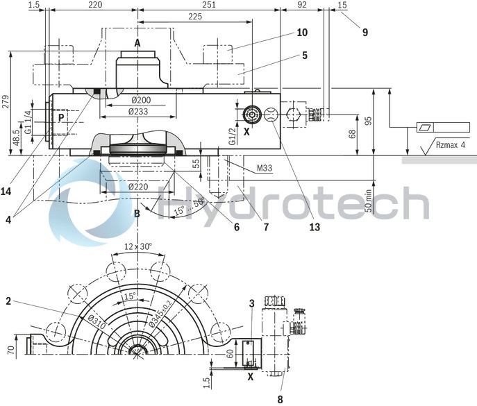
NG200
Dimensions in mm
|
|
|
Required surface quality of the valve contact surface |
|
3 |
Name plate |
|
4 |
Seal rings |
|
5 |
Counterflange (separate order, see "dimensional proposal for counterflange") |
|
6 |
Stroke of main poppet (see "Poppet geometry and determination of the minimum pilot pressure") |
|
7 |
Note: Valve contact face (e.g. pressing cylinders, bearing structures, etc.) must be sufficiently rigid. The prefill valve must not be loaded by bending. |
|
8 |
Directional valve (separate order); dimensions see data sheet 23178 (type 4WE 6 D...) or 22058 (type M-.SEW 6...) |
|
9 |
Space required to remove the mating connector |
|
10 |
Valve mounting screws (separate order) |
|
11 |
Threads for transport device (ring bolts), evenly distributed to circumference |
|
12 |
Measuring point, tightening torque MA = 30 Nm ±10% |
|
13 |
Additional pressure port; if not used, seal in a hydraulically tight way by means of suitable plug screws. |
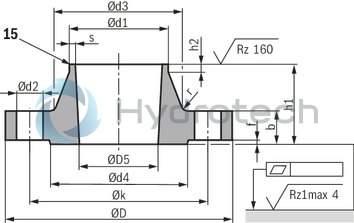
Dimensional proposal for counterflange (pos. 5)
Dimensions in mm
 |
|
Required surface quality of the valve contact surface |
|
Size |
32 | 40 | 50 | 63 | 80 | 100 | 125 | 160 | 200 | |
|
Maximum operating pressure pmax 1) |
350 bar | |||||||||
|
Recommended flange material |
C22 | S355J2G3 | ||||||||
| 1) | When using other counterflanges than the ones specified here, it may be necessary to reduce the operating pressure. |
Form of the welding gap (15):
Standard version s ≤ 16 gap form 22 DIN 2559 s > 16 gap form 3 DIN 2559 special version see DIN 2559|
NG |
Flange |
Neck |
Raised face |
||||||||||
|
Ød1 |
Ød2 |
ØD |
ØD5+2 |
b |
Øk |
h1 |
Ød3 |
s |
r |
h2 |
Ød4 |
f |
|
|
mm 1) |
mm |
mm |
mm |
mm |
mm |
mm |
mm |
mm 1) |
mm |
mm |
mm |
mm |
|
| 32 | 48.3 | 18 | 150 | 42 | 22 | 110 | 49 | 64 | 3.2 | 6 | 7 | 88 | 3 |
| 40 | 60.3 | 18 | 165 | 52 | 29 | 125 | 57 | 75 | 3.6 | 6 | 8 | 102 | 3 |
| 50 | 76.1 | 18 | 185 | 70 | 34 | 145 | 64 | 90 | 3.6 | 6 | 10 | 122 | 3 |
| 63 | 88.9 | 18 | 200 | 83 | 43 | 160 | 77 | 105 | 3.6 | 8 | 12 | 138 | 3 |
| 80 | 114.3 | 22 | 235 | 100 | 51 | 190 | 95 | 134 | 3.6 | 8 | 12 | 162 | 3 |
| 100 | 139.7 | 30 | 295 | 124 | 62 | 240 | 116 | 168 | 4 | 8 | 12 | 188 | 3 |
| 125 | 168.3 | 33 | 345 | 148 | 79 | 280 | 138 | 202 | 4.5 | 10 | 12 | 218 | 3 |
| 160 | 219.1 | 36 | 415 | 200 | 118 | 345 | 186 | 256 | 5.9 | 10 | 16 | 285 | 3 |
| 200 | 273 | 39 | 420 | 270 | 100 | 355 | 140 | 292 | 6.5 | 6 | 16 | - | - |
| 1) | For seamless steel pipes, wall thickness 16 according to DIN EN 10220 |
Valve mounting screws, counterflange (separate order)
|
Hexagon socket head cap screw ISO 4762 - 10.9-flZn (or DIN 912 - 10.9-flZn) |
Counterflange |
||||
|
Size |
Dimensions |
Quantity |
Tightening torque MA in Nm (±5 %) 1) |
Material number |
Material number |
|
32 |
M16 x 100 |
4 |
240 |
R913015640 |
R900842693 |
|
40 |
M16 x 110 |
4 |
240 |
R913015642 |
R900825610 |
|
50 |
M16 x 110 |
8 |
240 |
R913015642 |
R900826441 |
|
63 |
M16 x 130 |
8 |
240 |
R913014713 |
R900849622 |
|
80 |
M20 x 140 |
8 |
460 |
R913015675 |
R900862915 |
|
100 |
M27 x 180 |
8 |
1150 |
R913059494 |
R900834583 |
|
125 |
M30 x 200 |
8 |
1600 |
R913015753 |
R900861508 |
|
160 |
M33 x 260 |
12 |
2200 |
R913001904 |
R900846478 |
|
200 |
M36 x 320 |
16 |
2600 |
R913050473 |
R901205467 |
| 1) | Friction coefficient μtotal = 0.09 … 0.14; please adjust in case of changed surfaces; use a manual torque wrench. |
Notice:
The information on the hexagon socket head cap screws (type, length, tightening torque) refers exclusively to the use with the counterflanges listed above.
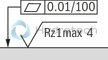
Poppet geometry and determination of the minimum pilot pressure
Dimensions in mm
|
A1 |
Effective area of the main poppet |
|
A2 |
Effective area of the pilot poppet |
|
A3 |
Effective area of the control spool |
|
s1 |
Stroke of the main poppet |
|
s2 |
Stroke of the control spool |
|
F1 |
Spring force of the valve spring |
|
F2 |
Spring force of the compression spring of the control spool |
|
Vst |
Pilot volume for opening the valve |
|
pÖ |
Cracking pressure (pressure differential at the main poppet for overcoming the spring force F1) |
|
pSt |
Pilot pressure at port X |
|
pB |
System pressure at port B |
|
NG |
A1 |
A2 1) |
A3 |
s1 |
s2 |
F1 |
F2 |
VstX |
Unchecking ratio |
|
|
cm² |
cm² |
cm² |
mm |
mm |
N |
N |
cm³ |
Without pre-decompression 2) |
With pre-decompression 3) |
|
| 32 | 8.04 | 0.5 | 2.01 | 8.5 | 6.5 | 9 … 22 | 58 … 109 | 1.3 | 4 | 0.3 |
| 40 | 13.52 | 0.79 | 3.14 | 10 | 7 | 14 … 29 | 93 … 162 | 2.2 | 4.3 | 0.3 |
| 50 | 21.24 | 1.13 | 4.71 | 12.5 | 9 | 23 … 49 | 149 … 261 | 4.2 | 4.5 | 0.3 |
| 63 | 32.67 | 1.77 | 7.07 | 14.5 | 11 | 35 … 63 | 206 … 348 | 7.8 | 4.6 | 0.3 |
| 80 | 49.02 | 2.54 | 10.18 | 17 | 13 | 57 … 127 | 310 … 579 | 13.2 | 4.8 | 0.3 |
| 100 | 73.13 | 3.8 | 15.9 | 22 | 16 | 81 … 193 | 476 … 952 | 25.5 | 4.6 | 0.2 |
| 125 | 120.76 | 5.72 | 28.27 | 30 | 22.5 | 135 … 319 | 878 … 1,667 | 59.4 | 4.3 | 0.2 |
| 160 | 196.07 | 9.08 | 45.36 | 40 | 27 | 241 … 516 | 1,335 … 2,395 | 122 | 4.3 | 0.2 |
| 200 | 314.16 | - | 78.54 | 48 | 34 | 425 … 850 | 2,389 … 3,822 | 267 | 4 | - |
| 1) | Is omitted for version "without pre-decompression" (ZSF...0...) |
| 2) | Without pre-decompression |
| 3) | (With pre-decompression on request) |

Example: Type ZSF32...
pB = 30 bar ;
pSt = 4.0 x 30 bar = 120 bar
Nozzle fitting
|
Size |
32 | 40 | 50 | 63 | 80 | 100 | 125 | 160 | 200 | |
|
Nozzle Ø 1) |
mm |
0.8 | 1 | 1.2 | 1.5 | 4 | ||||
| 1) | Nozzle in channel P installed at the factory |