
BOSCH REXROTH
4WRSEH6V12LD-3X/G24K0/A1V-280
R900618927
High-Response Directonal Valves
Prop. dir. valves: WRS* 6.-3x/
BOSCH REXROTH
MATERIAL: R900618927
SUMMARY: Prop. dir. valves: WRS* 6.-3x/
Quantity in stock: 0
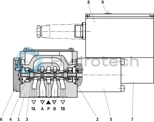
4/4 directional design
In principle, the function of these valves corresponds to the function of the 4/3-way version. With de-energized solenoid, the control spool is, however, held in a fail-safe position by a compression spring.
The 4/4 directional control valves are designed as direct operated devices in plate design. Operation is effected by means of control solenoid. The solenoid is controlled via integrated control electronics.
Set-up:
The valve basically consists of:
Housing (1) with connection surface Control spool (2) in sleeve (3) with compression springs (4) Solenoid (5) and cover (6) Position transducer (7) Integrated control electronics (8) Zero point adjustment accessible via Pg9 (9)
Functional description:
With de-energized solenoid (5), fail-safe position of the control spool (2) by compression spring (4) Direct operation of the control spool (2) by energization of a control solenoid (5)e.g. control of the solenoid
Displacement of the control spool (2) proportionally to the electric input signal Connection from P to A and B to T via orifice-type cross-sections with continuous or inflected linear flow characteristicsSwitching off the solenoid (5) The compression spring (4) brings the control spool (2) back into the fail-safe position
The 4/3 and 4/4 directional control valves are designed as direct operated devices in plate design. Operation is effected by means of control solenoids. The solenoids are controlled via integrated control electronics.
Set-up:
The valve basically consists of:
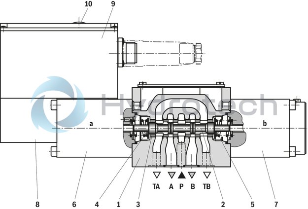
Housing (1) with connection surface Control spool (2) in sleeve (3) with compression springs (4 and 5) Solenoids (6 and 7) Position transducer (8) Integrated control electronics (9) Zero point adjustment (10) accessible via Pg9
Functional description:
4/3 directional design
With de-energized solenoids (6 and 7), mechanical central position of the control spool (2) by compression springs (4 and 5) Direct operation of the control spool (2) by energization of a control solenoide.g. control solenoid "b" (7)
Displacement of the control spool (2) to the left, proportionally to the electric input signal Connection from P to A and B to T via orifice-type cross-sections with continuous or inflected linear flow characteristics Switching off the solenoid (7) The compression spring (4) brings the control spool (2) back into the central position
In the de-energized condition, the control spool (2) is held in a mechanical central position by the control springs. This position does not correspond to the hydraulic central position!
When the electric valve control loop is closed and with command value presetting 0 (0 V with A1 and/or 12 mA with F1), the control spool (2) is positioned in the hydraulic central position.
|
01 |
02 |
03 |
04 |
05 |
06 |
07 |
08 |
09 |
10 |
11 |
12 |
13 |
14 |
15 |
|||
|
4WRS |
E |
H |
‒ |
3X |
/ |
G24 |
K0 |
/ |
V |
* |
|
01 |
High-response directional valves, direct operated, with electrical position feedback |
4WRS |
|
02 |
With integrated control electronics |
E |
|
03 |
Control spool/sleeve |
H |
|
04 |
Size 6 |
6 |
|
Size 10 |
10 |
|
|
Symbols; for the possible version, see "Symbols/Circuit diagrams" |
||
|
05 |
4/3-way version |
V |
|
4/4 directional design |
C3, C4 |
|
|
Installation side of the inductive position transducer with control spool symbol “V” |
||
|
06 |
4WRSEH.V...-3X/...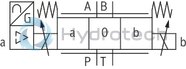
|
no code |
4WRSEH.VC...-3X/...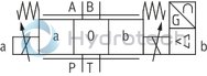
|
C |
|
|
Installation side of the inductive position transducer with control spool symbol “C3” and “C4” |
||
|
06 |
4WRSEH.C.B...-3X/...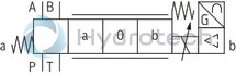
|
B |
4WRSEH.C...-3X/...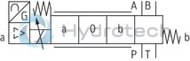
|
no code |
|
|
Rated flow at 70 bar valve pressure differential |
||
|
07 |
Size 6 |
|
|
4l/min |
04 1) |
|
|
12 l/min |
12 |
|
|
24 l/min |
24 |
|
|
40 l/min |
40 2) |
|
|
50 l/min |
50 3) |
|
|
Size 10 |
||
|
50 l/min |
50 |
|
|
100 l/min |
100 |
|
|
Flow characteristic |
||
|
08 |
Linear |
L |
|
Inflected characteristic curve 40% |
P |
|
|
Control spool overlap |
||
|
09 |
0 ... 0,5% negativ |
E 4) |
|
0 ... 0,5 % positiv |
D 4) |
|
|
10 |
Component series 30 ... 39 (30 ... 39: unchanged installation and connection dimensions) |
3X |
|
Supply voltage of the control electronics |
||
|
11 |
Direct voltage 24 V |
G24 |
|
Electrical connection |
||
|
12 |
Without mating connector, with connector according to E DIN 43 563-MA6, separate order |
K0 |
|
Electrical interface |
||
|
13 |
Command value input ±10 VDC |
A1 |
|
Command value input 4 ... 20 mA |
F1 |
|
|
Seal material |
||
|
14 |
FKM seals |
V |
|
15 |
Further details in the plain text |
* |
|
1) |
Use only in connection with flow characteristics "L" |
|
|
2) |
Only with “C” and “V” in connection with flow characteristics "P" |
|
|
3) |
Only with “V” in connection with flow characteristics "L" |
|
|
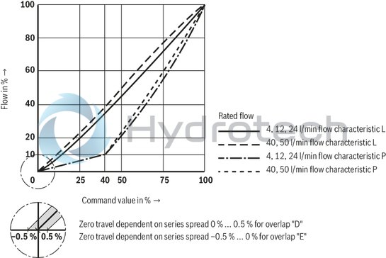
4) |
The control spool overlap in % is referred to the nominal stroke of the control spool. We recommend the D overlap for control tasks. Other control spool overlaps upon request! |
|
For applications outside these parameters, please consult us!
general
|
Type |
4WRSEH | |||
|
Size |
6 | 10 | ||
|
Component series |
3X | |||
|
Installation position |
any, preferably horizontal | |||
|
Weight |
Valve with one solenoid |
kg |
2.3 | 6 |
|
Valve with two solenoids |
kg |
3 | 7.3 | |
|
Storage temperature range |
°C |
-20 … +80 | ||
|
Ambient temperature range |
°C |
-20 … +50 | ||
hydraulic
|
Type |
4WRSEH | |||
|
Size |
6 | 10 | ||
|
Maximum operating pressure |
bar |
315 | ||
|
Maximum operating pressure |
Port P |
bar |
315 | |
|
Port A |
bar |
315 | ||
|
Port B |
bar |
315 | ||
|
Port T |
bar |
315 | 210 | |
|
Maximum flow |
l/min |
80 | 180 | |
|
Nominal flow 1) |
l/min |
4 12 24 40 50 |
50 100 |
|
|
Hydraulic fluid temperature range |
°C |
-20 … +80 | ||
|
Viscosity range |
Maximum admissible |
mm²/s |
20 … 380 | |
|
Recommended |
mm²/s |
30 … 46 | ||
|
Maximum admissible degree of contamination of the hydraulic fluid, cleanliness class according to ISO 4406 (c) 2) |
Class 18/16/13 according to ISO 4406 (c) | |||
|
Hysteresis |
% |
< 0.05 | ||
|
Response sensitivity |
% |
< 0.03 | ||
|
Range of inversion |
% |
< 0.03 | ||
| 1) | at 70 bar valve pressure differential |
| 2) | The cleanliness classes specified for the components must be adhered to in hydraulic systems. Effective filtration prevents faults and simultaneously increases the life cycle of the components. For the selection of the filters, see www.boschrexroth.com/filter. |
hydraulic
|
Nominal flow |
l/min |
50 | 100 | 4, 12 | 24 | 40 | |
|
Limitation of use |
Symbols C, C3, C5 |
bar |
250 | 150 | 315 | 160 | |
|
Symbols C1, C4 |
bar |
150 | 100 | 315 | 200 | 100 | |
|
Hydraulic fluid |
Classification |
Suitable sealing materials |
Standards |
|
Mineral oils and related hydrocarbons |
HL, HLP |
NBR / FKM |
DIN 51524 |
|
Phosphoric acid esters |
HFD-R |
FKM |
|
|
Important information on hydraulic fluids: For more information and data on the use of other hydraulic fluids please contact us. |
|||
electrical
|
Type |
4WRSEH | ||
|
Size |
6 | 10 | |
|
Voltage type |
Direct voltage | ||
|
Type of signal |
analog | ||
|
Protection class according to DIN EN 60529 |
IP65 (with mating connector mounted and locked) | ||
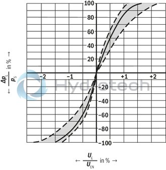
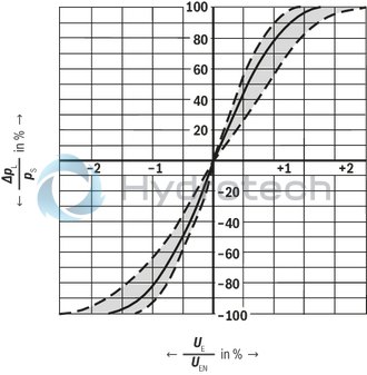
(measured with HLP46, ϑÖl = 40 ±5 °C)
Pressure-signal characteristic curve, ps = 100 bar4WRSEH 6...L....
NG6
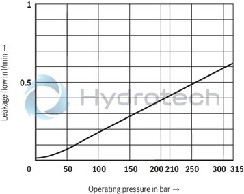
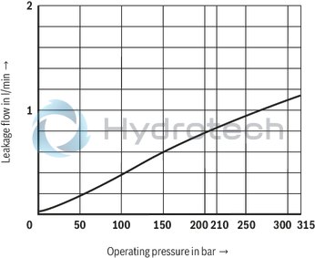
Zero flow (typical)
NG6
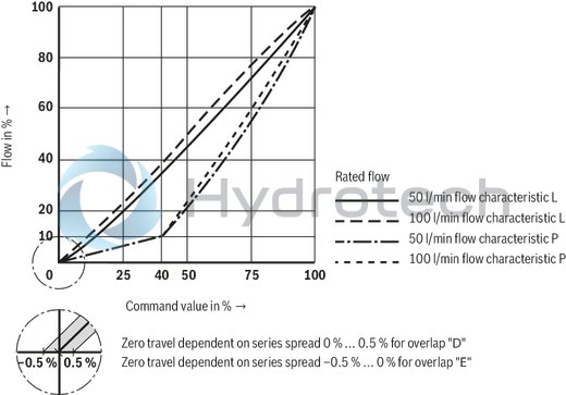
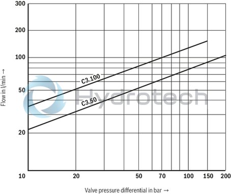
Flow characteristic curve
NG6
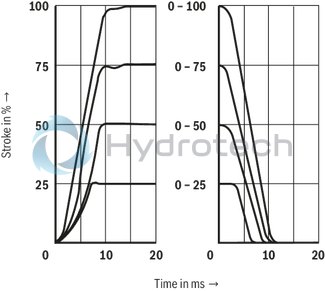
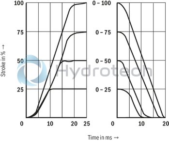
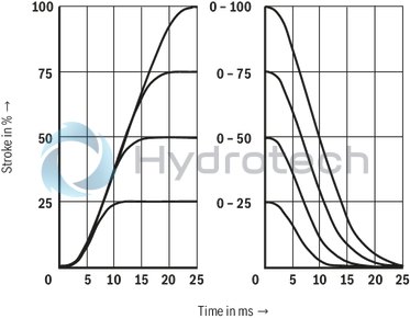
Transition function4/3 directional design
NG6
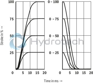
Transition function 4/4 directional design
NG6
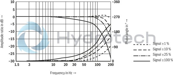
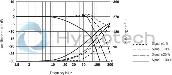
Frequency response 4/3 directional design
NG6
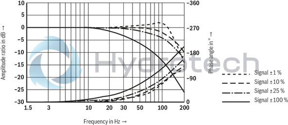
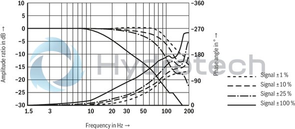
Frequency response 4/4 directional design
NG6
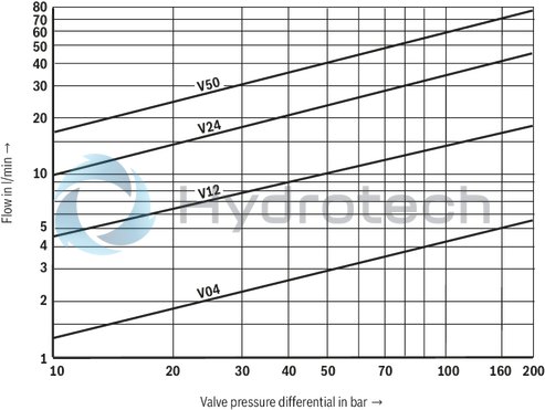
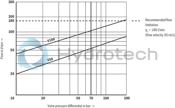
Flow/load function with maximum valve opening (tolerance ±10 %) (4/3 directional design)
NG6
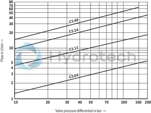
Flow/load function with maximum valve opening (tolerance ±10 %) (4/4 directional design)
NG6
Pressure-signal characteristic curve, ps = 100 bar4WRSEH 10...L....
Size 10
Zero flow (typical)
Size 10
Flow characteristic curve
Size 10
Transition function4/3 directional design
Size 10
Transition function 4/4 directional design
Size 10
Frequency response 4/3 directional design
Size 10
Frequency response 4/4 directional design
Size 10
Flow/load function with maximum valve opening (tolerance ±10 %) (4/3 directional design)
Size 10
Flow/load function with maximum valve opening (tolerance ±10 %) (4/4 directional design)
Size 10
Symbols
4/3-way version
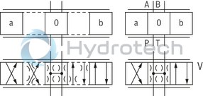
Symbols
4/4 directional design
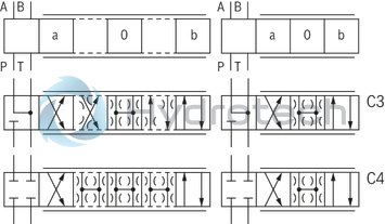
4WRSEH.V...-3X/...
4WRSEH.VC...-3X/...
4WRSEH.C.B...-3X/...
4WRSEH.C...-3X/...
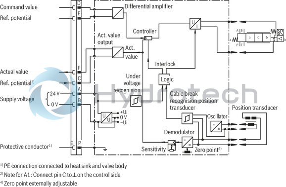
|
Pin assignment |
Contact |
Assignment interface "A1" |
Assignment interface "F1" |
|
Power supply |
A |
24 VDC (19,4 ... 35 VDC), Imax = 2 A (NG6), Imax = 2.8 A (NG10), impulse load: 4 A |
|
|
B |
0 V
|
||
|
Reference potential actual value |
C |
Reference potential for contact F; |
Reference potential for contact F |
|
Differential amplifier input (command value) |
D |
±10 V command value; Re > 50 kΩ |
4 ...20 mA command value; Re > 100 Ω |
|
E |
Reference potential for contact D |
||
|
Measuring output (actual value) |
F |
± 10 V; Imax = 2 mA |
4 ... 20 mA; load resistance maximum 500 Ω |
|
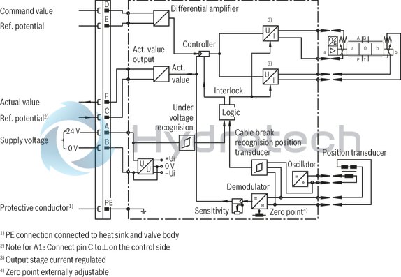
PE |
connected to cooling element and valve housing |
||
Command value: Positive command value (0...10 V or 12...20 mA) at D and reference potential at E result in flow from P → A and B → T.
Negative command value (0...-10 V or 12...4 mA) at D and reference potential at E result in flow from P → B and A → T.
Actual value: Positive signal (0...10 V or 12...20 mA) at F and reference potential at C result in flow from P → A.
Connection line: Recommendation:
up to 25 m line length: Type LiYCY 7 x 0.75 mm² up to 50 m line length: Type LiYCY 7 x 1.0 mm²External diameter 6.5 … 11 mm and/or 8 ... 13.5 mm
Connect shield to ⊥ only on the supply side.
4/3-way version
4/4 directional design
Notice:
Electrical signals provided via control electronics (e. g. actual value) must not be used to switch off safety-relevant machine functions. (See also the European standard "Safety requirements for fluid-powered systems and their components - Hydraulics", EN 982!)
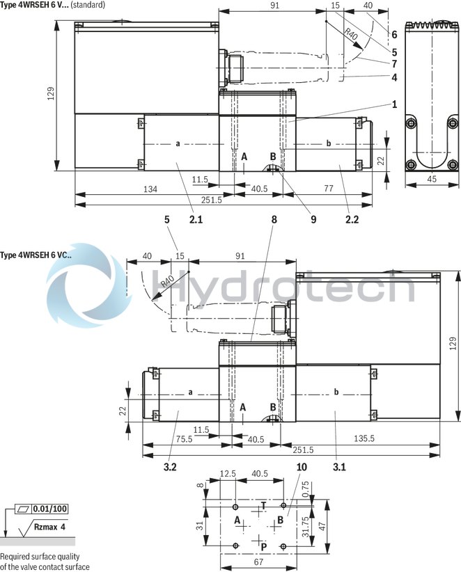
|
1 |
Valve housing |
|
2.1 |
Control solenoid "a" with inductive position transducer |
|
2.2 |
Control solenoid “b” |
|
3.1 |
Control solenoid "b" with inductive position transducer |
|
3.2 |
Control solenoid “a” |
|
4 |
Mating connector according to DIN EN 175201-804, separate order |
|
5 |
Space required to remove the mating connector |
|
6 |
Additional space required for bending radius of the connection line |
|
7 |
Cable bending radius |
|
8 |
Name plate |
|
9 |
Identical seal rings for ports A, B, P, and T |
|
10 |
Machined valve contact surface; Porting pattern according to DIN 24340-A6 and ISO 4401-03-02-0-05 |
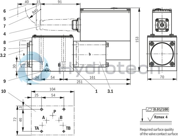
Recommended valve mounting screws (separate order):
4 hexagon socket head cap screws ISO 4762 - M5 x 30 - 10.9-flZn-240h-L (Friction coefficient total = 0.09 ... 0.14)Tightening torque MA = 7 Nm ± 10 % , material no. R913000316
Typ 4WRSEH 6 C.B...
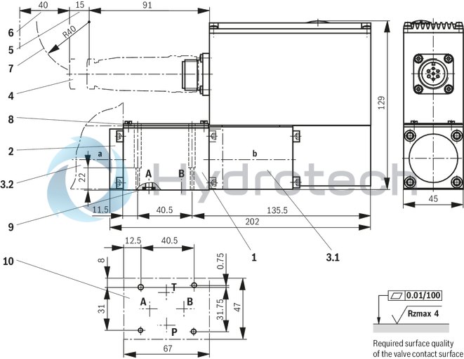
|
1 |
Valve housing |
|
2 |
Cover |
|
3.1 |
Control solenoid "b" with inductive position transducer |
|
3.2 |
Control solenoid "a" with inductive position transducer |
|
4 |
Mating connector according to DIN EN 175201-804, separate order |
|
5 |
Space required to remove the mating connector |
|
6 |
Additional space required for bending radius of the connection line |
|
7 |
Cable bending radius |
|
8 |
Name plate |
|
9 |
Identical seal rings for ports A, B, P, and T |
|
10 |
Machined valve contact surface; Porting pattern according to DIN 24340-A6 and ISO 4401-03-02-0-05 |
Recommended valve mounting screws (separate order):
4 hexagon socket head cap screws ISO 4762 - M5 x 30 - 10.9-flZn-240h-L (Friction coefficient total = 0.09 ... 0.14)Tightening torque MA = 7 Nm ± 10 % , material no. R913000316
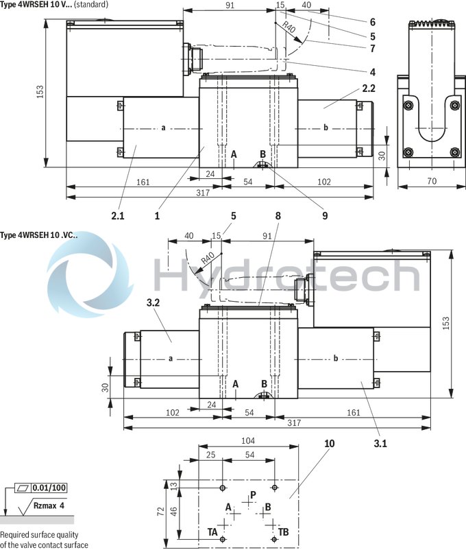
|
1 |
Valve housing |
|
2.1 |
Control solenoid "a" with inductive position transducer |
|
2.2 |
Control solenoid “b” |
|
3.1 |
Control solenoid "b" with inductive position transducer |
|
3.2 |
Control solenoid “a” |
|
4 |
Mating connector according to DIN EN 175201-804, separate order |
|
5 |
Space required to remove the mating connector |
|
6 |
Additional space required for bending radius of the connection line |
|
7 |
Cable bending radius |
|
8 |
Name plate |
|
9 |
Identical seal rings for ports A, B, P, and T |
|
10 |
Machined valve contact surface; Porting pattern according to DIN 24340-A10 and ISO 4401-05-05-0-05 |
Recommended valve mounting screws (separate order):
4 hexagon socket head cap screws ISO 4762 - M6 x 40 - 10.9-flZn-240h-L (Friction coefficient total = 0.09 ... 0.14)Tightening torque MA = 12.5 Nm ± 10 %, material no. R913000058
Typ 4WRSEH 10 C.B...
|
1 |
Valve housing |
|
2 |
Cover |
|
3.1 |
Control solenoid "b" with inductive position transducer |
|
3.2 |
Control solenoid "a" with inductive position transducer |
|
4 |
Mating connector according to DIN EN 175201-804, separate order |
|
5 |
Space required to remove the mating connector |
|
6 |
Additional space required for bending radius of the connection line |
|
7 |
Cable bending radius |
|
8 |
Name plate |
|
9 |
Identical seal rings for ports A, B, P, and T |
|
10 |
Machined valve contact surface; Porting pattern according to DIN 24340-A10 and ISO 4401-05-05-0-05 |
Recommended valve mounting screws (separate order):
4 hexagon socket head cap screws ISO 4762 - M6 x 40 - 10.9-flZn-240h-L (Friction coefficient total = 0.09 ... 0.14)Tightening torque MA = 12.5 Nm ± 10 %, material no. R913000058
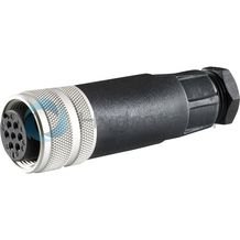
Mating connectors for valves with round connector, 6-pole + PE
7P Z31
Mating connectors for valves with round connector, 6-pole + PE
7P Z31
For valves with round connector according to EN 175201-804, 6-pole + PE as well as 6-pole, compatible with VG 95328Data sheet
Spare parts & repair