
BOSCH REXROTH
4WRTE32E1-600L-4X/6EG24K31/A1M
R900739977
All Other Products
Prop. dir. valves: WRT* 32.-4x/
BOSCH REXROTH
MATERIAL: R900739977
SUMMARY: Prop. dir. valves: WRT* 32.-4x/
Quantity in stock: 0
Valves of type 4WRTE are pilot-operated directional control valves with electrical position feedback, integrated electronics (OBE) and optional spool position monitoring.
Set-up
The valve basically consists of 3 main assemblies:
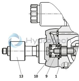
Housing (1) with main stage control spool (2) and optional spool position monitoring (13) Integrated electronics (optionally with electronics protection membrane (14)) with inductive position transducer (3) of the main stage Pilot control valve (4) with control spool/socket unit (5), inductive position transducer (6) and pressure feed back for central position of the main stage control spool (2)
Function
With de-energized proportional solenoids (7; 8) central position of the main stage control spool (2) due to centering spring (9) and pressure feed back Control of the main stage control spool (2) via the pilot control valve (4) → the main stage control spool (2) is positioned in a regulated manner Controlling the control spool of the pilot control valve (4) by changing the solenoid force of the proportional solenoids (7; 8) Connection of the command and actual values in the integrated electronics Pilot oil supply to the pilot control valve internally via port P or externally via port X Pilot oil return internally via port T or externally via Y to the tank With a command value of 0 V, the electronics control the main stage control spool (2) in central position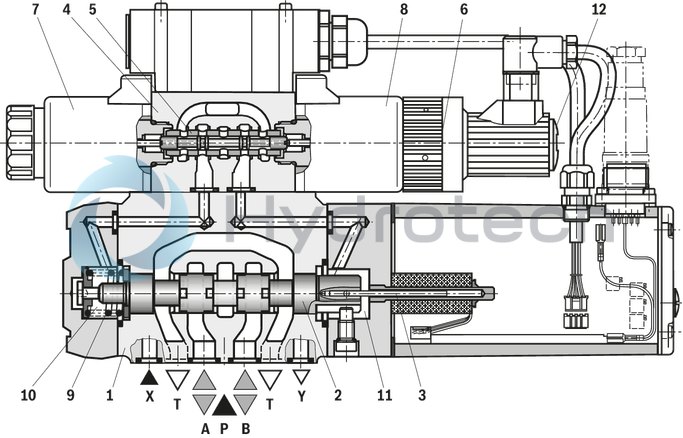
Spool position monitoring
The spool positions of the main stage control spool (2) are detected by the inductive position switch (13) and displayed via two switching outputs with a preset logic. If the fixedly set switching points are exceeded, the deviation from the zero position is monitored within the control spool overlap (see "Accessories").
The switching signals can be used in a superior control for monitoring functions. The electrical connection is implemented separately via a 4-pole connector M12x1 with two pins for signal output and two pins for voltage supply.
Area of application
The valve can be used in safety-related two-channel applications (category 3, PL d and category 4, PL e according to EN 13849-1) as switch-off element for one channel. The valve meets the requirements of a secure start inhibitor according to EN 60204, stop category 0.
If safety requirements are needed, the supply voltage of the valve must be safely disconnected based on the
required safety level (category PL).
Depending on the application and the requirements of work equipment-specific standards according to EN 13849-1, the user must provide appropriate monitoring/plausibility checks which comply with the required
diagnostic coverage DCavg using a superior control.
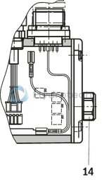
Electronics protection membrane "-967"
To prevent condensate formation in the housing of the integrated electronics (OBE), an electronics protection
membrane (14) can be used.
Recommended for use outside industry-standard conditions with high ambient air humidity and significant cyclic temperature changes (e. g. outdoors).
Failure of supply voltage
Integrated electronics de-energize the solenoid in case of supply voltage failure or cable break Automatic pressure control on the same level in the control chambers (10 and 11) by the pilot control valve In case of pressure supply failure, centering of the main stage control spool by centering spring (9) Central position of the main stage control spool (2)
Notices:
Failure of the supply voltage will lead to an abrupt standstill of the control axis. The acceleration forces occurring in this connection may cause machine damage.With control spool symbols E, E1-, W6- and W8-, the centering spring (9) sets the main stage control spool (2) in central position, control spools V- and V1 are switched to the preferred direction P to B and A to T in a tolerance range of 1% to a maximum of 11% of the control spool stroke. The PG fitting (12) must not be opened. Mechanical adjustment of the adjustment nut located below is prohibited and damages the valve. The zero point has been adjusted at the factory. Changes in the zero point may result in damage to the system and may only be implemented by instructed specialists. If the pilot control valve or the electronics are exchanged, the zero point has to be adjusted once again by instructed specialists.
 |
 |
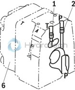
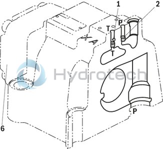
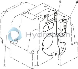
Pilot oil supply
(schematic illustration)
Size 10
Size 16
Size 25
Size 27
Size 32
Size 35
|
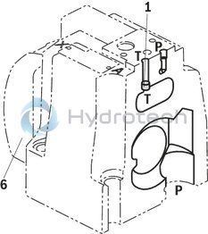
1 |
Plug screw M6 according to DIN 906, wrench size 3 – pilot oil return |
|
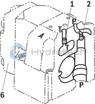
2 |
Plug screw M6 according to DIN 906, wrench size 3 – pilot oil supply |
|
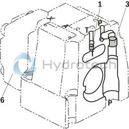
3 |
Plug screw M12 x 1.5 according DIN 906, wrench size 6 – pilot oil supply |
|
4 |
Plug screw M10 x 1 according to DIN 906, wrench size 5 – pilot oil return |
|
5 |
Plug screw M10 x 1 according DIN 906, wrench size 5 – pilot oil supply |
|
6 |
Main stage housing cover (opposite the OBE) |
Pilot oil supply external: 2, 3, 5 closed
Pilot oil supply internal: 2, 3, 5 open
Pilot oil return external: 1, 4 closed
Pilot oil return internal: 1, 4 open
"No code" version
External pilot oil supply
External pilot oil return
In this version, the pilot oil is supplied from a separate control circuit (external).
The pilot oil return is not directed into channel T of the main valve, but is separately directed to the tank via port Y (external).
Version "E"
Internal pilot oil supply
External pilot oil return
With this version, the pilot oil is supplied from channel P of the main valve (internally).
The pilot oil return is not directed into channel T of the main valve, but is separately directed to the tank via port Y (external).
In the subplate, port X is to be closed.
Version "ET"
Internal pilot oil supply
Internal pilot oil return
With this version, the pilot oil is supplied from channel P of the main valve (internally).
The pilot oil is directly returned to channel T of the main valve (internally).
In the subplate, ports X and Y are to be closed.
Version "T"
External pilot oil supply
Internal pilot oil return
In this version, the pilot oil is supplied from a separate control circuit (external).
The pilot oil is directly returned to channel T of the main valve (internally).
In the subplate, port Y is to be closed.
|
01 |
02 |
03 |
04 |
05 |
06 |
07 |
08 |
09 |
10 |
11 |
12 |
13 |
14 |
15 |
16 |
17 |
|||
|
4 |
WRT |
E |
‒ |
4X |
/ |
6E |
G24 |
K31 |
/ |
* |
|
01 |
4 main ports |
4 |
|
02 |
High-response directional valve, pilot operated |
WRT |
|
03 |
With integrated electronics (OBE) |
E |
|
04 |
Without spool position monitoring |
no code |
|
With spool position monitoring (NG16 … NG35 only) |
M |
|
|
05 |
Size 10 |
10 |
|
Size 16 |
16 |
|
|
Size 25 |
25 |
|
|
Size 27 |
27 |
|
|
Size 32 |
32 |
|
|
Size 35 |
35 |
|
|
06 |
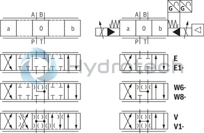
Symbols; for the possible version, see "Symbols/Circuit diagrams" |
|
|
Rated flow (Δp = 5 bar/control edge) |
||
|
07 |
Size 10 |
|
|
25l/min 1) |
25 |
|
|
50l/min 2) |
50 |
|
|
90 l/min |
100 |
|
|
Size 16 |
||
|
150l/min 3) |
150 |
|
|
220l/min |
220 |
|
|
Size 25 |
||
|
220l/min |
220 |
|
|
350 l/min |
350 |
|
|
Size 27 |
||
|
500 l/min |
500 |
|
|
Size 32 |
||
|
400 l/min |
400 |
|
|
600 l/min |
600 |
|
|
Size 35 |
||
|
1000 l/min |
1000 |
|
|
Flow characteristic |
||
|
08 |
Linear |
L |
|
Linear with fine control range |
P |
|
|
09 |
Component series 40 … 49 (40 … 49: unchanged installation and mounting dimensions) |
4X |
|
Pilot control valve |
||
|
10 |
Proportional solenoid with detachable coil (NG6) |
6E |
|
Power supply |
||
|
11 |
Direct voltage 24 V |
G24 |
|
Pilot oil flow |
||
|
12 |
External pilot oil supply, external pilot oil return |
no code |
|
Internal pilot oil supply, external pilot oil return |
E |
|
|
Pilot oil supply internal, pilot oil return internal |
ET |
|
|
External pilot oil supply, internal pilot oil return |
T |
|
|
Electrical connection |
||
|
13 |
Without mating connector, with connector according to DIN EN 175201-804 |
K31 4) |
|
Electrical interface |
||
|
14 |
Command value/actual value ±10 V |
A1 |
|
Command value/actual value 4 … 20 mA |
F1 |
|
|
Command value/actual value ±10 V, enable signal (pin C) |
A5 5) |
|
|
Seal material |
||
|
15 |
NBR seals |
M |
|
FKM seals |
V |
|
|
16 |
Without electronics protection membrane |
no code |
|
With electronics protection membrane |
-967 |
|
|
17 |
Further details in the plain text |
* |
| 1) | Symbol E, W6-, W8- and V only with flow characteristic "L" |
| 2) | Symbol E1-, W8- and V1 only with flow characteristic "L" |
| 3) | Symbol V1 only with flow characteristic "L" |
| 4) | Mating connectors, separate order, see "Accessories" |
| 5) | When replacing the component series 3X by 4X, the electronics interface is to be defined with A5 (enable signal at pin C). |
For applications outside these parameters, please consult us!
general
|
Type |
4WRTE | ||||||
|
Size |
10 | 16 | 25 | 27 | 32 | 35 | |
|
Component series |
4X | ||||||
|
Installation position |
any, preferably horizontal | ||||||
|
Earth |
kg |
8.7 | 11.2 | 16.8 | 17 | 31.5 | 34 |
|
Ambient temperature range |
°C |
-20 … +50 | |||||
|
Sine test according to DIN EN 60068-2-6 |
10 ... 2000 Hz / maximum 10 g / 10 cycles / 3 axes | ||||||
|
Noise test according to DIN EN 60068-2-64 |
20 ... 2000 Hz / 10 gRMS / 30 g peak / 30 min / 3 axes | ||||||
|
Transport shock according to DIN EN 60068-2-27 |
15 g / 11 ms / 3 shocks / 3 axes | ||||||
|
MTTFD values according to EN ISO 13849 1) |
Years |
150 | |||||
|
Damp heat according to DIN EN 60068-2-30 |
Variant 2: +25 °C … +55 °C, 90 % … 97 % relative humidity, 2 cycles á 24 hours | ||||||
| 1) | With symbol E, E1, W6 and W8; in longitudinal control spool direction, there is sufficient positive overlap without shock/vibration load; observe the installation orientation with regard to the main direction of acceleration. |
hydraulic
|
Type |
4WRTE | ||||||||
|
Size |
10 | 16 | 25 | 27 | 32 | 35 | |||
|
Maximum operating pressure |
bar |
350 | 270 | 350 | |||||
|
Maximum operating pressure |
Port P |
bar |
350 | 270 | 350 | ||||
|
Anschluss A |
bar |
350 | 270 | 350 | |||||
|
Port B |
bar |
350 | 270 | 350 | |||||
|
Maximum operating pressure |
Pilot control valve |
Pilot oil supply 1) |
bar |
25 … 315 | |||||
|
Maximum return flow pressure |
Port T |
Internal pilot oil supply |
static < 10 bar | ||||||
|
Port T |
External pilot oil supply |
bar |
315 | 250 | 210 | 250 | |||
|
Port Y |
static < 10 bar | ||||||||
|
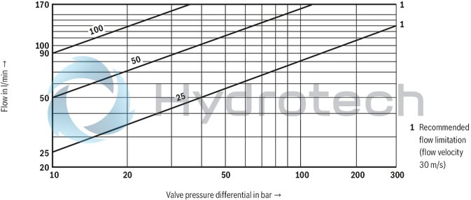
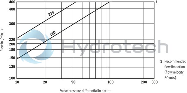
Nominal flow 2) |
l/min |
25 50 100 |
125 150 200 220 |
220 350 |
500 |
400 600 |
1000 | ||
|
Maximum flow |
l/min |
170 | 460 | 870 | 1000 | 1600 | 3000 | ||
|
Pilot flow 3) |
l/min |
7 | 14 | 20 | 27 | 29 | |||
|
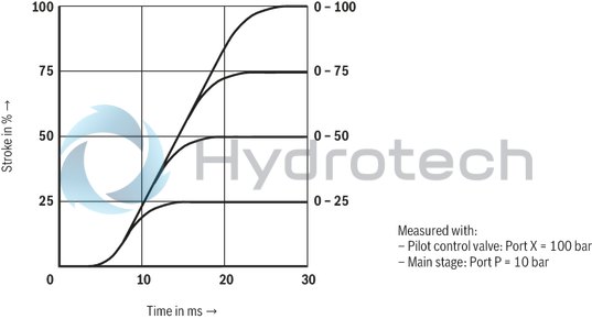
Pilot volume 0 … 100% |
cm³ |
1.1 | 2.9 | 6.8 | 17.7 | 33.9 | |||
|
Hydraulic fluid temperature range |
°C |
-20 … +80 | |||||||
|
preferably |
°C |
+40 … +80 | |||||||
|
Viscosity range |
mm²/s |
20 … 380 | |||||||
|
preferably |
mm²/s |
30 … 45 | |||||||
|
Maximum admissible degree of contamination of the hydraulic fluid, cleanliness class according to ISO 4406 (c) 4) |
Class 18/16/13 according to ISO 4406 (c) | ||||||||
|
Hysteresis |
% |
≤ 0.1 | |||||||
|
Response sensitivity |
% |
≤ 0.05 | |||||||
|
Temperature drift |
%/10° C |
< 0.3 | |||||||
| 1) | For perfect system behavior, we recommend an external pilot oil supply for pressures above 210 bar. |
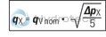
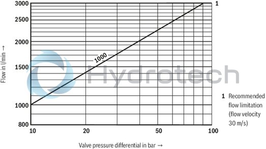
| 2) | qV nom ±10% with Δp = 5 bar/control edge; flow for deviating Δp see formula. |
| 3) | At port X or Y with stepped input signal from 0 to 100% (315 bar) |
| 4) | The cleanliness classes specified for the components must be adhered to in hydraulic systems. Effective filtration prevents faults and simultaneously increases the life cycle of the components. For the selection of the filters, see www.boschrexroth.com/filter. |
|
Hydraulic fluid |
Classification |
Suitable sealing materials |
Standards |
Data sheet |
|
|
Mineral oils |
HL, HLP, HLPD, HVLP, HVLPD |
NBR, FKM |
DIN 51524 |
90220 |
|
|
Bio-degradable |
Insoluble in water |
HETG |
NBR, FKM |
ISO 15380 |
90221 |
|
HEES |
FKM |
||||
|
Soluble in water |
HEPG |
FKM |
ISO 15380 |
||
|
Flame-resistant |
Water-free |
HFDU, HFDR |
FKM |
ISO 12922 |
90222 |
|
Containing water |
HFC (Fuchs Hydrotherm 46M, Petrofer Ultra Safe 620) |
NBR |
ISO 12922 |
90223 |
|
|
Important information on hydraulic fluids: For further information and data on the use of other hydraulic fluids, please refer to the data sheets above or contact us. There may be limitations regarding the technical valve data (temperature, pressure range, life cycle, maintenance intervals, etc.). The ignition temperature of the hydraulic fluid used must be 40 K higher than the maximum solenoid surface temperature. Flame-resistant – containing water: Maximum operating pressure 210 bar Maximum pressure differential per control edge 175 bar Pressure pre-loading at the tank port >20% of the pressure differential, otherwise increased cavitation erosion Life cycle as compared to operation with mineral oil HL, HLP 50 … 100% Maximum hydraulic fluid temperature 50 °C |
|||||
electrical
|
Type |
4WRTE | ||
|
Voltage type |
Direct voltage | ||
|
Power supply |
Nominal voltage |
VDC |
24 |
|
Lower limit value |
VDC |
18 | |
|
Upper limit value |
VDC |
35 | |
|
Maximum admissible residual ripple 1) |
Vpp |
2.5 | |
|
Maximum current consumption |
of the amplifier |
A |
1.6 |
|
of the amplifier (impulse current) |
A |
2.7 | |
|
Maximum coil temperature 2) |
°C |
150 | |
|
Duty cycle |
% |
100 | |
|
Maximum power consumption |
72 VA (average = 24 VA) | ||
|
Required fuse protection |
AT |
4 (time-lag) | |
|
Protection class according to DIN EN 60529 |
IP65 (If a suitable and a correctly mounted mating connector are used.) | ||
|
Zero point calibration 3) |
% |
≤ 1 | |
|
Voltage input "A1" (differential input) |
Measurement range |
VDC |
-10 ... +10 |
|
Input resistance |
Ω |
100 | |
|
Current input "F1" |
Input current |
mA |
4 ... 20 |
|
Input resistance |
Ω |
100 | |
|
Enable input "A5" |
Low level |
VDC |
0 ... 2 |
|
High level |
VDC |
> 11 | |
| 1) | Observe the absolute limit values of the supply voltage. |
| 2) | Due to the surface temperatures of the solenoid coils, the standards ISO 13732-1 and ISO 4413 (contact protection) must be observed. |
| 3) | Related to the pressure-signal characteristic curve (symbol V), ex works |
Inductive position switch: Electrical connection
The electrical connection is realized via a 4-pole mating connector (separate order, see "Accessories") with connection thread M12 x 1.
Inductive position switch: Switching logics
Position switch on side A, monitored spool position "0"
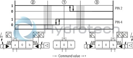
|
➀ |
Central position (mechanical control spool overlap) |
|
➁ |
Valve opening P→B |
|
➂ |
Valve opening P→A |
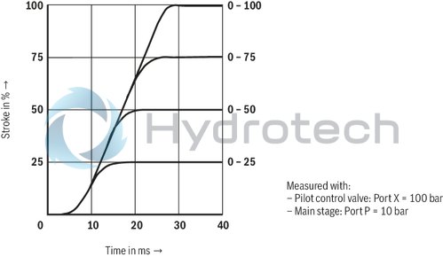
(measured with HLP46, ϑOil = 40 ±5 °C)
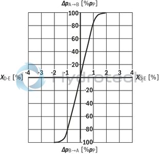
Pressure amplification measured with p = 100 bar)
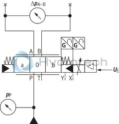 |
 |
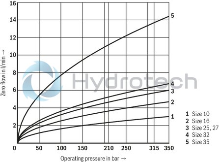
Maximum zero flow of the main stage (symbol V) with pilot control valve
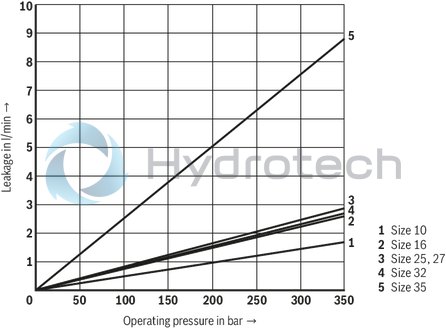
Maximum internal leakage of the main stage (symbol W) with pilot control valve
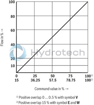
Flow command value function (Δp = 5 bar/control edge)
Symbol E, W and V, Version "L"
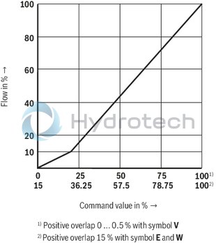
Flow command value function (Δp = 5 bar/control edge)
Symbol E, W and V, Version „P“
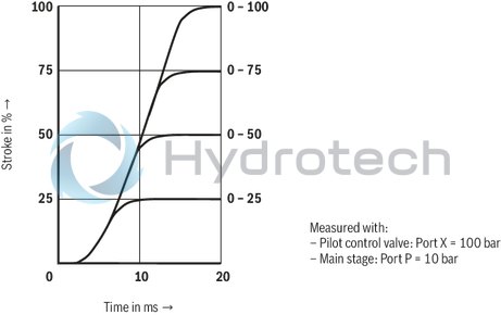
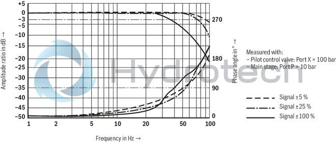
Size 10
Transition function with stepped electric input signals
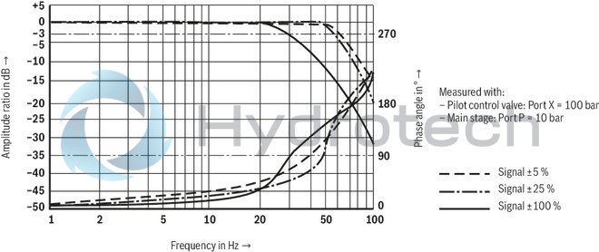
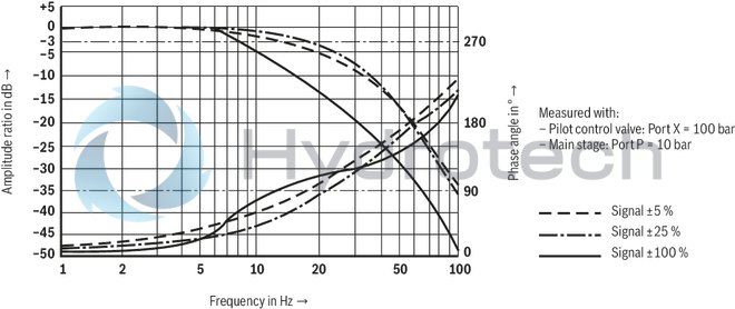
Frequency response
Flow/load function with maximum valve opening (tolerance ±10 %)
Size 16
Transition function with stepped electric input signals
Frequency response
Flow/load function with maximum valve opening (tolerance ±10 %)
Size 25 and 27
Transition function with stepped electric input signals
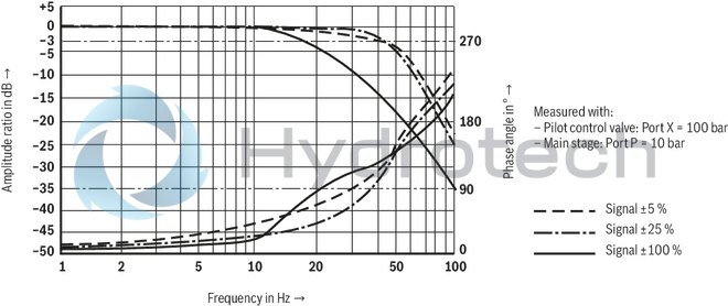
Frequency response
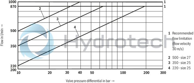
Flow/load function with maximum valve opening (tolerance ±10 %)
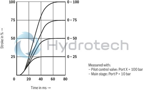
Size 32
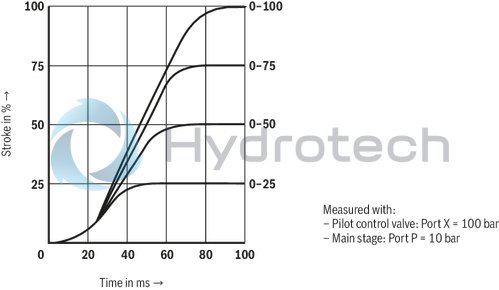
Transition function with stepped electric input signals
Frequency response
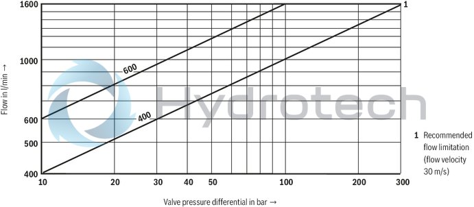
Flow/load function with maximum valve opening (tolerance ±10 %)
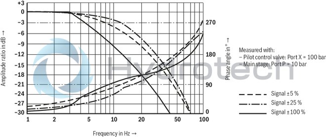
Size 35
Transition function with stepped electric input signals
Frequency response
Flow/load function with maximum valve opening (tolerance ±10 %)
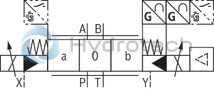
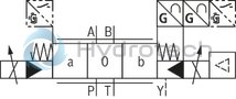
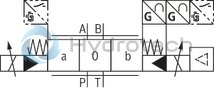
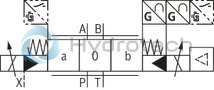
Symbols
|
Symbol E1-, V1- and W8-: |
|
|
P → A: qv max P → B: qv/2 |
B → T: qv/2 A → T: qv max |
|
Version |
simple |
Detailed |
|
no code |
 |
 |
|
"E" |
 |
|
|
"ET" |
 |
|
|
"T" |
 |
|
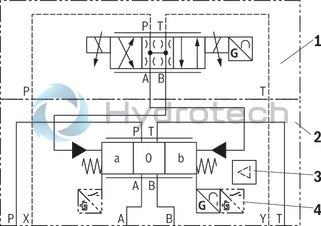
1 |
Pilot control valve |
|
2 |
Main valve |
|
3 |
Integrated electronics (OBE) |
|
4 |
Design with spool position monitoring "M" |
Notice:
Representation according to DIN ISO 1219-1. Hydraulic interim positions are shown by dashes.
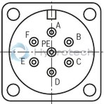
Electrical connections and assignment
Connector pin assignment
|
Pin |
Signal |
Assignment interface "A1" |
Assignment interface "F1" |
Signal with interface A5 |
|
A |
Power supply |
24 VDC |
||
|
B |
0 V |
|||
|
C |
Reference potential (actual value)/enable signal |
Reference potential actual value (pin F) |
Enable signal >11 VDC |
|
|
D |
Differential amplifier input (command value) |
± 10 V |
4 ... 20 mA |
± 10 V |
|
E |
0 V reference potential (pin D) |
0 V reference potential (pin D and F) |
||
|
F |
Measuring output (actual value) |
± 10 V |
4 ... 20 mA |
± 10 V |
|
PE |
Functional ground (directly connected to valve housing) |
|||
 |
Command value |
Reference potential at E and positive command value at D result in flow from P → A and B → T. |
|
Reference potential at E and negative command value at D result in flow from P → B and A → T. |
||
|
Connection cable (recommendation) |
Up to 25 m cable length type LiYCY 7 x 0,75 mm2 |
|
|
Up to 50 m cable length type LiYCY 7 x 1,0 mm2 |
||
|
Connect shield on PE only on the supply side |
Notices:
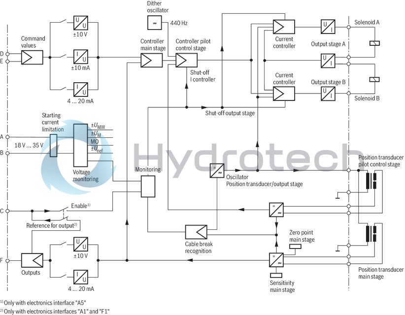
Electrical signals provided via valve electronics (e.g. actual value) must not be used to switch off safety-relevant machine functions. Mating connectors, separate order, see "Accessories".Block diagram: Integrated electronics (OBE)
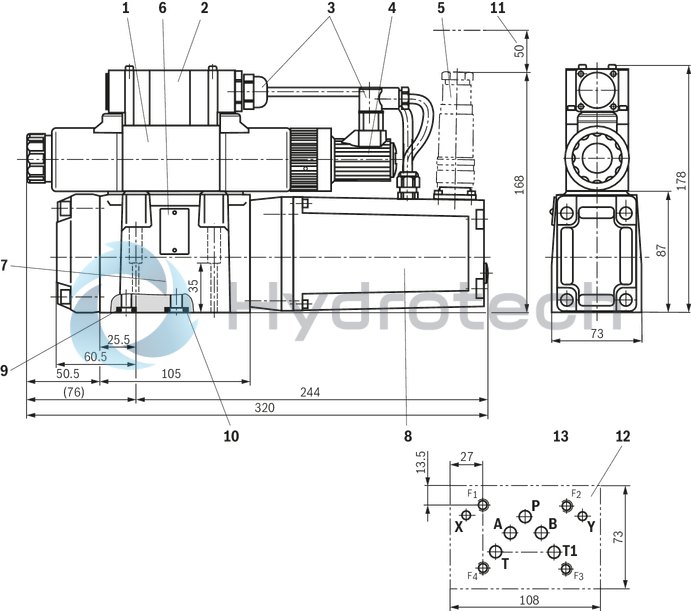
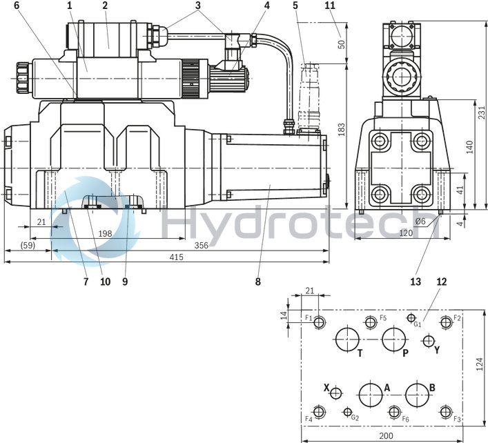
Size 10
Dimensions in mm
 |
|
Required surface quality of the valve contact surface |
|
1 |
Pilot control valve |
|
2 |
Electrical connection |
|
3 |
Wiring and mating connector |
|
4 |
Inductive position transducer (pilot control valve) |
|
5 |
Mating connectors, separate order, see "Accessories" |
|
6 |
Name plate |
|
7 |
Main valve |
|
8 |
Integrated electronics (OBE) and inductive position transducer (main valve) |
|
9 |
Identical seal rings for ports X and Y |
|
10 |
Identical seal rings for ports A, B, P and T (T1) |
|
11 |
Space required for connection cable and to remove the mating connector |
|
12 |
Machined valve contact surface; Porting pattern according to ISO 4401-05-05-0-05 (ports X, Y as required) |
Valve mounting screws (separate order):
4 hexagon socket head cap screws ISO 4762 - M6 x 45 - 10.9-CM-Fe-ZnNi-5-Cn-T0-H-B
Tightening torque MA = 13,5 Nm ±10 %, material no. R913043777
or
4 hexagon socket head cap screws ISO 4762 - M6 x 45 - 10.9
Tightening torque MA = 15,5 Nm ±10 %, ot included in the Rexroth delivery range
Notice:
The tightening torque of the hexagon socket head cap screws refers to maximum operating pressure!
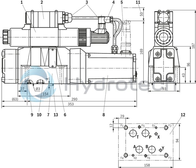
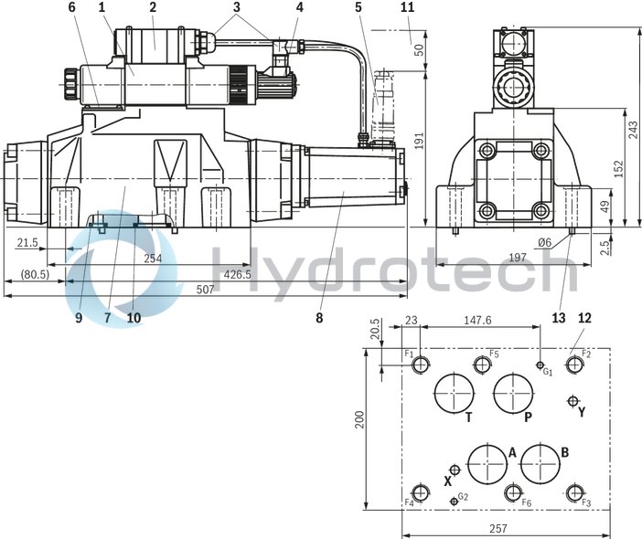
Size 16
Dimensions in mm
|
|
|
Required surface quality of the valve contact surface |
|
1 |
Pilot control valve |
|
2 |
Electrical connection |
|
3 |
Wiring and mating connector |
|
4 |
Inductive position transducer (pilot control valve) |
|
5 |
Mating connectors, separate order, see "Accessories" |
|
6 |
Name plate |
|
7 |
Main valve |
|
8 |
Integrated electronics (OBE) and inductive position transducer (main valve) |
|
9 |
Identical seal rings for ports X and Y |
|
10 |
Identical seal rings for ports A, B, P and T (T1) |
|
11 |
Space required for connection cable and to remove the mating connector |
|
12 |
Machined valve contact surface, porting pattern according to ISO 4401-07-07-0-05 (ports X, Y as required). Deviating from the standard: ports A, B, P, T – Ø20 mm |
|
13 |
Locking pin |
Valve mounting screws (separate order):
2 hexagon socket head cap screws ISO 4762 - M6 x 60 - 10.9-CM-Fe-ZnNi-5-Cn-T0-H-BTightening torque MA = 12.2 Nm ±10 %, material no. R913043410 4 hexagon socket head cap screws ISO 4762 - M10 x 60 - 10.9-flZn/nc/480h/C
Tightening torque MA = 58 Nm ±20 %, material no. R913014770
or
2 hexagon socket head cap screws ISO 4762 - M6 x 60 - 10.9Tightening torque MA = 15,5 Nm ±10 %, not included in the Rexroth delivery range 4 Hexagon socket head cap screws ISO 4762 - M10 x 60 - 10.9
Tightening torque MA = 75 Nm ±20 %, not included in the Rexroth delivery range
Notice:
The tightening torque of the hexagon socket head cap screws refers to maximum operating pressure.
Size 25
Dimensions in mm

|
|
|
Required surface quality of the valve contact surface |
|
1 |
Pilot control valve |
|
2 |
Electrical connection |
|
3 |
Wiring and mating connector |
|
4 |
Inductive position transducer (pilot control valve) |
|
5 |
Mating connectors, separate order, see "Accessories" |
|
6 |
Name plate |
|
7 |
Main valve |
|
8 |
Integrated electronics (OBE) and inductive position transducer (main valve) |
|
9 |
Identical seal rings for ports X and Y |
|
10 |
Identical seal rings for ports A, B, P, and T |
|
11 |
Space required for connection cable and to remove the mating connector |
|
12 |
Machined valve contact surface; Porting pattern according to ISO 4401-08-08-0-05 (ports X, Y as required) |
|
13 |
Locking pin |
Valve mounting screws (separate order):
6 hexagon socket head cap screws ISO 4762 - M12 x 60 - 10.9-flZn/nc/480h/C
Tightening torque MA = 100 Nm ±20 %, Material-Nr. R913015613
or
6 hexagon socket head cap screws ISO 4762 - M12 x 60 - 10.9
Tightening torque MA = 130 Nm ±20 %, not included in the Rexroth delivery range
Notice:
The tightening torque of the hexagon socket head cap screws refers to maximum operating pressure.
Size 27
Dimensions in mm
|
|
|
Required surface quality of the valve contact surface |
|
1 |
Pilot control valve |
|
2 |
Electrical connection |
|
3 |
Wiring and mating connector |
|
4 |
Inductive position transducer (pilot control valve) |
|
5 |
Mating connectors, separate order, see "Accessories" |
|
6 |
Name plate |
|
7 |
Main valve |
|
8 |
Integrated electronics (OBE) and inductive position transducer (main valve) |
|
9 |
Identical seal rings for ports X and Y |
|
10 |
Identical seal rings for ports A, B, P, and T |
|
11 |
Space required for connection cable and to remove the mating connector |
|
12 |
Machined valve contact surface; Porting pattern according to ISO 4401-08-08-0-05 (Ports X, Y as required) |
|
13 |
Locking pin |
Valve mounting screws (separate order):
6 hexagon socket head cap screws ISO 4762 - M12 x 60 - 10.9-flZn/nc/480h/C
Tightening torque MA = 100 Nm ±20 %, Material-Nr. R913015613
or
6 hexagon socket head cap screws ISO 4762 - M12 x 60 - 10.9
Tightening torque MA = 130 Nm ±20 %, not included in the Rexroth delivery range
Notice:
The tightening torque of the hexagon socket head cap screws refers to maximum operating pressure.
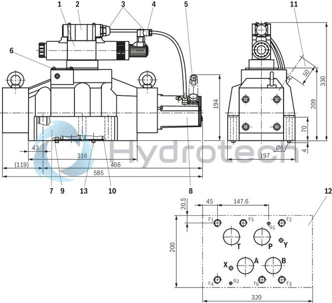
Size 32
Size 32
Dimensions in mm
|
|
|
Required surface quality of the valve contact surface |
|
1 |
Pilot control valve |
|
2 |
Electrical connection |
|
3 |
Wiring and mating connector |
|
4 |
Inductive position transducer (pilot control valve) |
|
5 |
Mating connectors, separate order, see "Accessories" |
|
6 |
Name plate |
|
7 |
Main valve |
|
8 |
Integrated electronics (OBE) and inductive position transducer (main valve) |
|
9 |
Identical seal rings for ports X and Y |
|
10 |
Identical seal rings for ports A, B, P, and T |
|
11 |
Space required to remove the mating connector |
|
12 |
Machined valve contact surface; Porting pattern according to ISO 4401-10-09-0-05 (Ports X, Y as required). Deviating from the standard: |
|
13 |
Locking pin |
Valve mounting screws (separate order):
6 hexagon socket head cap screws ISO 4762 - M20 x 80 - 10.9-flZn/nc/480h/C
Tightening torque MA = 340 Nm ±20 %, material no. R913008472
or
6 hexagon socket head cap screws ISO 4762 - M20 x 80 - 10.9
Tightening torque MA = 430 Nm ±20 %, not included in the Rexroth delivery range
Notice:
The tightening torque of the hexagon socket head cap screws refers to maximum operating pressure.
Size 35
Size 35
Dimensions in mm
|
|
|
Required surface quality of the valve contact surface |
|
1 |
Pilot control valve |
|
2 |
Electrical connection |
|
3 |
Wiring and mating connector |
|
4 |
Inductive position transducer (pilot control valve) |
|
5 |
Mating connectors, separate order, see "Accessories" |
|
6 |
Name plate |
|
7 |
Main valve |
|
8 |
Integrated electronics (OBE) and inductive position transducer (main valve) |
|
9 |
Identical seal rings for ports X and Y |
|
10 |
Identical seal rings for ports A, B, P, and T |
|
11 |
Space required for connection cable and to remove the mating connector |
|
12 |
Machined valve contact surface; Porting pattern according to ISO 4401-10-09-0-05 (Ports X, Y as required). Deviating from the standard: |
|
13 |
Locking pin |
Valve mounting screws (separate order):
6 hexagon socket head cap screws ISO 4762 - M20 x 100 - 10.9-flZn/nc/480h/C
Tightening torque MA = 465 Nm ±20 %, material no. R913015670
or
6 hexagon socket head cap screws ISO 4762 - M20 x 100 - 10.9
Tightening torque MA = 610 Nm ±20 %, not included in the Rexroth delivery range
Notice:
The tightening torque of the hexagon socket head cap screws refers to maximum operating pressure.
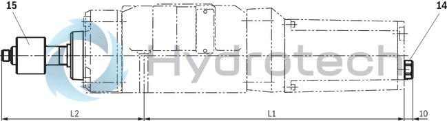
Spool position monitoring "M" and electronics protection membrane "-967"
Dimensions in mm
|
14 |
Electronics protection membrane "-967" |
|
15 |
Spool position monitoring "M", optional |
|
NG |
L1 |
L2 |
|
mm |
mm |
|
| 10 | 240 | |
| 16 | 286 | 151 |
| 25 | 347 | 143 |
| 27 | 353 | 144 |
| 32 | 422 | 168 |
| 35 | 463 | 201 |
Notice:
The dimensions are nominal dimensions which are subject to tolerances.
Project planning, installation and commissioning
When designing safety-related controls, observe the applicable industry-specific standards and regulations. Due to the flexible use of valves in systems, the user has to check and ensure that the product properties comply with all functional and safety requirements of the overall system. Make sure that there are no switching shocks and that the valve control spool does not vibrate. Valves with spool position indicator may only be installed, adjusted, commissioned and maintained by specialists trained in hydraulics and electronics. Improper work at safety-related parts of controls may result in personal injury and damage to property.
The following applies to all work carried out at the valve:
Valves with spool position indicator must not be disassembled. The parts of the valves must not be exchanged. Integrated throttles must not be removed or modified. The spool position indicator may only be adjusted by the valve manufacturer.Mating connectors for valves with round connector, 6-pole + PE
7P Z31
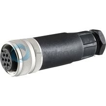
Mating connectors for valves with round connector, 6-pole + PE
7P Z31
For valves with round connector according to EN 175201-804, 6-pole + PE as well as 6-pole, compatible with VG 95328Data sheet
Spare parts & repair
Mating connectors for valves with round connector, 6-pole + PE, shielded, with assembled connection line
7P Z31 +
Mating connectors for valves with round connector, 6-pole + PE, shielded, with assembled connection line
7P Z31 +
For valves with round connector according to EN 175201-804, 6-pole + PE as well as 6-pole, compatible with VG 95328Data sheet
Spare parts & repair
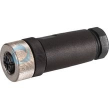
Mating connectors for sensors and valves with connector “K24”, “K35” and “K72”, M12 x 1
4P Z24
Mating connectors for sensors and valves with connector “K24”, “K35” and “K72”, M12 x 1
4P Z24
For sensors and valves with connector “K24”, “K35” and “K72” Mating connectors M12, 4-pole, line cross-section 0.75 mm2Data sheet
Spare parts & repair
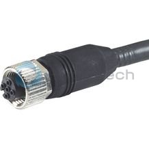
Mating connectors for sensors and valves with connector “K24”, “K35” and “K72”, M12 x 1, with assembled connection line
4P Z24 +
Mating connectors for sensors and valves with connector “K24”, “K35” and “K72”, M12 x 1, with assembled connection line
4P Z24 +
For sensors and valves with connector “K24”, “K35” and “K72” Mating connectors M12, 4-pole, line cross-section 0.75 mm2Data sheet
Spare parts & repair
Mating connectors for sensors and valves with connector “K24”, “K35” and “K72”, M12 x 1, with assembled connection line, cable shielded
4P M12 +
Mating connectors for sensors and valves with connector “K24”, “K35” and “K72”, M12 x 1, with assembled connection line, cable shielded
4P M12 +
For sensors and valves with connector “K24”, “K35” and “K72” Cable sets M12, 4-pole, line cross-section 0.34 mm2Data sheet
Spare parts & repair