
BOSCH REXROTH
Z2FRM6TB2-2X/32QRV
R900908807
Flow Control Throttle Valves
Flow-/throttle valves: Z2FRM 6.-2x/
BOSCH REXROTH
MATERIAL: R900908807
SUMMARY: Flow-/throttle valves: Z2FRM 6.-2x/
Quantity in stock: 0
The valve type Z2FRM is a 2-way flow control valve in sandwich plate design. It is used for pressure and temperature-independent flow stabilization.
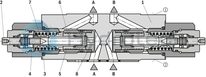
The valves basically consist of housing (1) and one or two flow control cartridges.
Throttling of the flow from channel A➁/B➁ to channel A➀/B➀ is realized at the throttling point (3). The throttle cross-section is set by rotation of the adjustment type (2) between the throttling point (3) and the throttle bolt (4).
For pressure-independent flow stabilization in channel A➀/B➀, a pressure compensator (5) is connected downstream to the throttling point (3).
The pressure compensator (5) is pressed by the compression spring (7) against the plug screw (8) and remains in open position if there is no flow through the valve. When there is a flow through the valve, the pressure in channel A➁/B➁ applies a force on the pressure compensator (5). It is set to control position until the forces are balanced. If the pressure in channel A➁/B➁ rises, the pressure compensator (5) moves in closing direction until the forces are balanced again. Due to this continuous compensation of the pressure compensator, a constant flow is obtained.
The free return flow from channel A➀/B➀ to channel A➁/B➁ is via the check valve (6).
Type Z2FRM 6 C…
|
➀ |
component side |
|
➁ |
plate side |
|
01 |
02 |
03 |
04 |
05 |
06 |
07 |
08 |
09 |
10 |
11 |
12 |
||
|
Z |
2FRM |
6 |
B |
2 |
– |
2X |
/ |
R |
V |
* |
|
01 |
Sandwich plate design |
Z |
|
02 |
2-way flow control valve |
2FRM |
|
03 |
Size 6 |
6 |
|
Flow control function (discharge control) in |
||
|
04 |
Channel A |
A |
|
Channel B |
B |
|
|
Channel A and B |
C |
|
|
Channel T 1) |
T |
|
|
05 |
Without closing of the pressure compensator |
B |
|
Adjustment type |
||
|
06 |
With internal hexagon |
2 |
|
07 |
Component series 20 ... 29 (20 ... 29: unchanged installation and connection dimensions) |
2X |
|
Flow |
||
|
08 |
up to 6.0 l/min |
6Q |
|
up to 32.0 l/min |
32Q |
|
|
09 |
With check valve |
R |
|
Seal material |
||
|
10 |
FKM seals (other seals upon request) |
V |
|
Observe compatibility of seals with hydraulic fluid used. (Other seals upon request) |
||
|
11 |
no code |
|
|
With locating hole |
/602) |
|
|
12 |
Further details in the plain text |
* |
| 1) By rotation around the longitudinal axis, a flow control function in channel P (supply control) is realized. Also refer to the dimensions, version "T". | |
| 2) Locking pin ISO 8752-3x8-St, material no. R900005694 (separate order) |
Preferred types and standard units are contained in the EPS (standard price list).
general
|
Size |
6 | ||
|
Weight |
Flow control function in channel A, B, T |
kg |
1.3 |
|
Flow control function in channel A, B |
kg |
1.4 | |
|
Installation position |
any | ||
|
Ambient temperature range |
°C |
-20 … +50 | |
hydraulic
|
Size |
6 | ||
|
Maximum operating pressure |
bar |
315 | |
|
Minimum pressure differential |
at qv max |
bar |
18 |
|
at qv min |
bar |
7 | |
|
Pressure stable (qV max) to Δp = 315 bar |
% |
± 3 | |
|
Flow |
at qv max |
l/min |
6 32 |
|
at qv min |
l/min |
0.05 0.25 |
|
|
Hydraulic fluid |
see table | ||
|
Hydraulic fluid temperature range |
°C |
-20 … +80 | |
|
Viscosity range |
mm²/s |
10 … 800 | |
|
Maximum admissible degree of contamination of the hydraulic fluid 1) |
Class 20/18/15 according to ISO 4406 (c) | ||
| 1) | The cleanliness classes specified for the components must be adhered to in hydraulic systems. Effective filtration prevents faults and simultaneously increases the life cycle of the components. For the selection of the filters, see www.boschrexroth.com/filter. |
|
Hydraulic fluid |
Classification |
Suitable sealing materials |
Standards |
|
|
Mineral oils and related hydrocarbons |
HL, HLP, HLPD
|
FKM |
DIN 51524 |
|
|
Environmentally compatible |
Insoluble in water |
HETG |
FKM |
ISO 15380 |
|
HEES |
FKM
|
|||
|
Soluble in water |
HEPG |
FKM |
ISO 15380 |
|
|
Containing water |
Water-free |
HFDU, HFDR |
FKM |
ISO 12922 |
|
Important information on hydraulic fluids! For further information and data on the use of other hydraulic fluids, please refer to data sheet 90220 or contact us! There may be limitations regarding the technical valve data (temperature, pressure range, life cycle, maintenance intervals, etc.)! |
||||
For applications outside these parameters, please consult us!
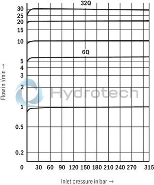
(measured with HLP46, ϑOil = 40 ±5 °C)
Δp-qV characteristic curves (via check valve; orifice closed)

Flow qV depending on inlet pressure pE
|
➀ |
component side |
|
➁ |
plate side |
Type Z2FRM 6 A…

Type Z2FRM 6 B…

Type Z2FRM 6 C…

Type Z2FRM 6 T…

Version "A" and "B"
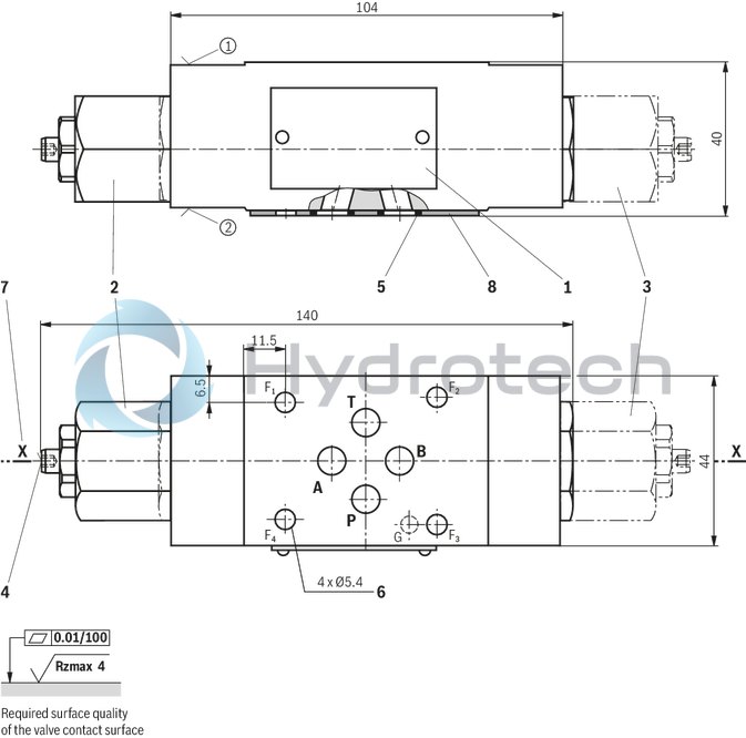
Dimensions in mm
|
➀ |
Component side – porting pattern according to ISO 4401-03-02-0-05 (with locating hole Ø3 x 5 mm deep) |
|
➁ |
plate side – porting pattern according to DIN 24340 form A (without locating hole), or ISO 4401-03-02-0-05 (with locating hole for locking pin ISO 8752-3x8-St; version "/60") |
|
1 |
Name plate |
|
2 |
Flow control cartridge at flow control in channel A, hexagon SW27; MA = 50 Nm |
|
3 |
Flow control cartridge at flow control in channel B, hexagon SW27; MA = 50 Nm |
|
4 |
Adjustment type with internal hexagon SW3 |
|
5 |
Identical seal rings for ports A➁, B➁, P➁, T➁ |
|
6 |
Valve mounting bores |
|
7 |
Modification from discharge to supply control is realized by rotation of the device around axis "X" – "X" |
|
8 |
Seal ring plate |
Valve mounting screws (separate order)
4 hexagon socket head cap screws ISO 4762 - M5 - 10.9
Notice!
Length and tightening torque of the valve mounting screws must be calculated according to the components mounted under and over the sandwich plate valve.
Version "C"
Dimensions in mm
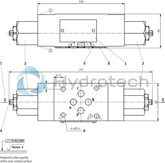
|
➀ |
Component side – porting pattern according to ISO 4401-03-02-0-05 (with locating hole Ø3 x 5 mm deep) |
|
➁ |
plate side – porting pattern according to DIN 24340 form A (without locating hole), or ISO 4401-03-02-0-05 (with locating hole for locking pin ISO 8752-3x8-St; version "/60") |
|
1 |
Name plate |
|
2 |
Flow control cartridge, hexagon SW27, MA = 50 Nm |
|
4 |
Adjustment type with internal hexagon SW3 |
|
5 |
Identical seal rings for ports A➁, B➁, P➁, T➁ |
|
6 |
Valve mounting bores |
|
7 |
Modification from discharge to supply control is realized by rotation of the device around axis "X" – "X" |
|
8 |
Seal ring plate |
Version "T"
Dimensions in mm

|
➀ |
Component side – porting pattern according to ISO 4401-03-02-0-05 (with locating hole Ø3 x 5 mm deep) |
|
➁ |
plate side – porting pattern according to DIN 24340 form A (without locating hole), or ISO 4401-03-02-0-05 (with locating hole for locking pin ISO 8752-3x8-St; version "/60") |
|
1 |
Name plate |
|
2 |
Flow control cartridge, hexagon SW27, MA = 50 Nm |
|
4 |
Adjustment type with internal hexagon SW3 |
|
5 |
Identical seal rings for ports A➁, B➁, P➁, T➁ |
|
6 |
Valve mounting bores |
|
7 |
Modification from discharge to supply control is realized by rotation of the device around axis "X" – "X" |
|
8 |
Seal ring plate |