

BOSCH REXROTH
4WRGE10V100L-1X/315G24K31/A1WC152M-613
R900975158
High-Response Directonal Valves
Prop. dir. valves: WRG* 10.-1x/
BOSCH REXROTH
MATERIAL: R900975158
SUMMARY: Prop. dir. valves: WRG* 10.-1x/
Quantity in stock: 0
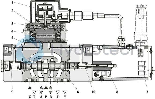
The 4/3 directional high-response valve is designed for subplate mounting, with position control and integrated control electronics. It controls the flow proportionally to the input signal, continuously from P to B and A to T or also from P to A and B to T.
Set-up:
The valve consists of four main assemblies:
low-friction pilot control valve (1) with dry 2-gap torque motor; valve housing (2) with orifices (3) and filter (4) Housing of the main stage (5) with spring-centered control spool (6) Control electronics (7) with amplifier to control the pilot control valve (1) and for the position control of the main control spool (6) inductive position transducer (8) for position sensing of the main control spool (6)
Functional description:
Control of the pilot control valve by means of a command value from 0 to ±10 V or from 0 to ± 10 mA Comparison command/actual value in the control electronics → In case of control deviation, the torque motor will be activated and the flapper plate will be deflected according to the control amplitude. Detuning of the control pressures using the control and fixed orifices → Deflection of the main control spool (6) Achievement of the position of the main control spool according to the command value presetting → Control deviation has been reduced to almost 0 V → Control process is completed Pilot oil supply to the pilot control valve internally via port P or externally via port X Pilot oil drain internally via port T or externally via Y to the tank
Notice:
In case of supply voltage failure, however with available operating pressure, the main control spool (6) will take an undefined position. The acceleration forces occurring in this connection may cause machine damage.
If a directional sandwich plate valve is used, the two control lines in the main stage will be short-circuited in case of power failure.
With control spool form E, E1- and Q2-, the centering spring (9, 10) bring the main control spool (6) in central position, V- and V1 control spools are switched to preferred direction P to B and A to T in a tolerance range of 1% to a maximum of 11% of the control spool stroke. In case of operating pressure failure and if no directional sandwich plate valve is used, you will observe the same behavior.
Type 4WRGE…-1X/…
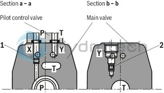
Pilot oil supply external; pilot oil drain external
In this version, the pilot oil is supplied from a separate control circuit (externally).
The pilot oil drain is not directed into the T channel of the main valve, but is separately directed to the tank via port Y (externally).
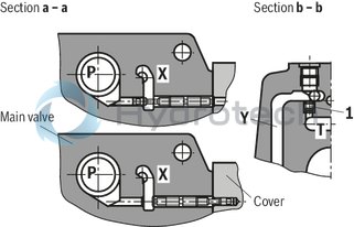
Type 4WRGE…-1X/…E…
Pilot oil supply internal, pilot oil drain external
In this version, the pilot oil is supplied from the P channel of the main valve (internally).
The pilot oil drain is not directed into the T channel of the main valve, but is separately directed to the tank via port Y (externally). In the subplate, port X is to be closed.
Type 4WRGE…-1X/…ET…
Pilot oil supply internal, pilot oil drain internal
In this version, the pilot oil is supplied from the P channel of the main valve (internally).
The pilot oil is directly drained to channel T of the main valve (internally). In the subplate, ports X and Y are to be closed.
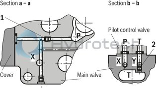
Type 4WRGE…-1X/…T…
Pilot oil supply external; pilot oil drain internal
In this version, the pilot oil is supplied from a separate control circuit (externally).
The pilot oil is directly drained to channel T of the main valve (internally). In the subplate, port Y is to be closed.
Position 1 and 2: Plug screw M6 DIN 906-8.8 SW 3
|
Pilot oil supply Section a - a |
External Internal |
1 1 |
closed open |
|
Pilot oil return Section b - b |
External Internal |
2 2 |
closed open |
|
Pilot oil supply Section a - a |
External Internal |
P P |
closed open |
|
Pilot oil return Section b - b |
External Internal |
1 1 |
closed open |
|
Pilot oil supply Section a - a |
External Internal |
1 1 |
closed open |
|
Pilot oil return Section b - b |
External Internal |
2 2 |
closed open |
|
01 |
02 |
03 |
04 |
05 |
06 |
07 |
08 |
09 |
10 |
11 |
12 |
13 |
14 |
15 |
|||
|
4 |
WRGE |
L |
‒ |
1X |
/ |
315 |
G24 |
K31 |
/ |
* |
|
01 |
4 main ports |
4 |
|
02 |
High-response directional valve |
WRGE |
|
03 |
Size 10 |
10 |
|
Size 16 |
16 |
|
|
Size 25 |
25 |
|
|
04 |
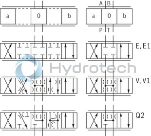
Symbols; for the possible version, see "Symbols/Circuit diagrams" |
E; E1-; V; V1-; Q2- |
|
Rated flow at 10 bar valve pressure differential |
||
|
05 |
NG10 |
|
|
50 l/min |
50 |
|
|
100 l/min |
100 |
|
|
NG16 |
||
|
125 l/min |
125 |
|
|
200 l/min |
200 |
|
|
NG25 |
||
|
250 l/min |
250 |
|
|
350 l/min |
350 |
|
|
Characteristic curve form |
||
|
06 |
Linear |
L |
|
07 |
Component series 10 ... 19 (10 ... 19: unchanged installation and connection dimensions) |
1X |
|
Pilot pressure |
||
|
08 |
10 … 315 bar |
315 |
|
09 |
Supply voltage 24 V |
G24 |
|
Pilot oil supply and return |
||
|
10 |
External pilot oil supply, external pilot oil return |
no code |
|
Internal pilot oil supply, external pilot oil return |
E |
|
|
Pilot oil supply internal, pilot oil return internal |
ET |
|
|
External pilot oil supply, internal pilot oil return |
T |
|
|
Electrical connection |
||
|
11 |
Without mating connector, with connector according to E DIN 43 563-MA6-3, separate order |
K9 |
|
12 |
Command value input ±10 VDC |
A1 |
|
Command value input ±10 mA |
C1 |
|
|
13 |
Without directional sandwich plate valve |
no code |
|
Withdirectional sandwich plate valve 24 V with connector DIN 43 650-AM2 Without mating connector |
WG152 |
|
|
14 |
NBR seals |
M 1) |
|
FKM seals |
V |
|
|
15 |
Further details in the plain text |
* |
|
1) |
Suitable for mineral oils (HL, HLP) according to DIN 51524 |
|
For applications outside these parameters, please consult us!
general
|
Type |
4WRGE | |||
|
Size |
10 | 16 | 25 | |
|
Component series |
1X | |||
|
Installation position |
any, preferably horizontal | |||
|
Earth |
kg |
8 | 9.8 | 18 |
|
Storage temperature range |
°C |
-20 … +80 | ||
|
Ambient temperature range |
°C |
-20 … +50 | ||
hydraulic
|
Type |
4WRGE | |||||
|
Size |
10 | 16 | 25 | |||
|
Maximum operating pressure |
bar |
315 | 350 | |||
|
Maximum operating pressure |
Port P |
bar |
315 | 350 | ||
|
Port A |
bar |
315 | 350 | |||
|
Port B |
bar |
315 | 350 | |||
|
Maximum operating pressure |
Pilot control valve |
Pilot oil supply |
bar |
10 … 315 | ||
|
Maximum return flow pressure |
Port T |
Internal pilot oil supply |
Pressure peaks <100 admissible | |||
|
Port T |
External pilot oil supply |
bar |
315 | 250 | ||
|
Port Y |
Pressure peaks <100 admissible | |||||
|
Nominal flow 1) |
l/min |
50 100 |
125 200 |
250 350 |
||
|
Maximum flow |
l/min |
170 | 460 | 870 | ||
|
Pilot flow |
l/min |
2 | ||||
|
Hydraulic fluid temperature range |
°C |
-20 … +80 | ||||
|
preferably |
°C |
+40 … +50 | ||||
|
Viscosity range |
mm²/s |
20 … 380 | ||||
|
preferably |
mm²/s |
30 … 45 | ||||
|
Maximum admissible degree of contamination of the hydraulic fluid, cleanliness class according to ISO 4406 (c) 2) |
Pilot control valve |
Class 18/16/13 according to ISO 4406 (c) | ||||
|
Main valve |
Class 20/18/15 according to ISO 4406 (c) | |||||
|
Main control spool stroke |
mm |
± 3.5 | ||||
|
Hysteresis |
% |
≤ 0.05 | ||||
|
Response sensitivity |
% |
≤ 0.2 | ||||
|
Range of inversion |
% |
≤ 0.04 | ||||
| 1) | qVnom ±10 % with valve differential pressure Δp = 10 bar |
| 2) | The cleanliness classes specified for the components must be adhered to in hydraulic systems. Effective filtration prevents faults and simultaneously increases the life cycle of the components. For the selection of the filters, see www.boschrexroth.com/filter. |
|
Hydraulic fluid |
Classification |
Suitable sealing materials |
Standards |
|
Mineral oils and related hydrocarbons |
HL, HLP |
NBR / FKM |
DIN 51524 |
|
For more information and data on the use of other hydraulic fluids please contact us. |
|||
electrical
|
Type |
4WRGE | ||||
|
Voltage type |
Direct voltage | ||||
|
Type of signal |
analog | ||||
|
Protection class according to DIN EN 60529 |
IP65 | ||||
|
Zero point calibration |
% |
≤ 2 | |||
|
Zero shift upon change of |
Hydraulic fluid temperature |
%/10 K |
< 0.2 | < 0.3 | < 0.4 |
|
Operating pressure |
%/100 bar |
< 0.02 | < 0.04 | < 0.06 | |
|
Return flow pressure |
% |
< 0.01 | < 0.02 | < 0.03 | |
measured with HLP46, ν = 32 mm2/s and ϑOil = 40 °C ± 5 °C
Pressure-signal characteristic curve (control spool V), ps = 210 bar
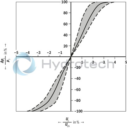
Zero flow at central control spool position "V"
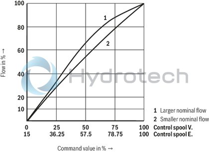
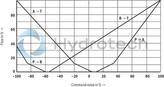
Flow; control spools E and V with linear characteristic curve "L"
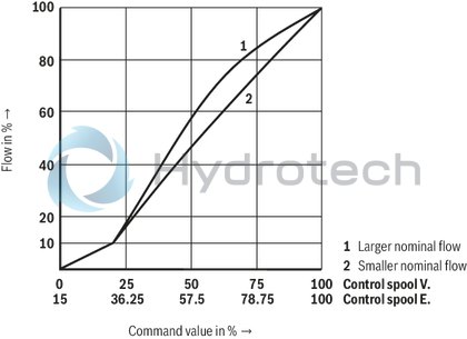
Flow; control spools E and V with inflected characteristic curve “P"
Flow; control spool Q2
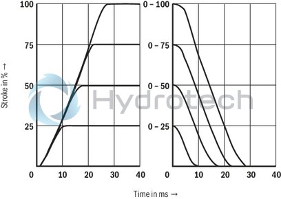
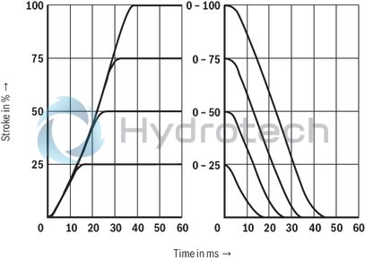
Transition function with stepped electric input signals
Size 10
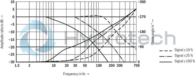
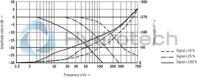
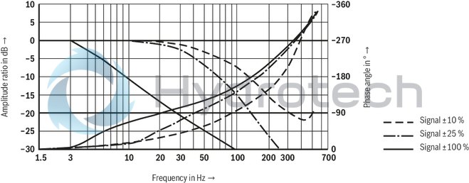
Frequency response
Size 10
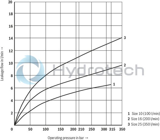
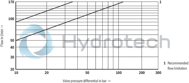
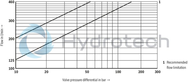
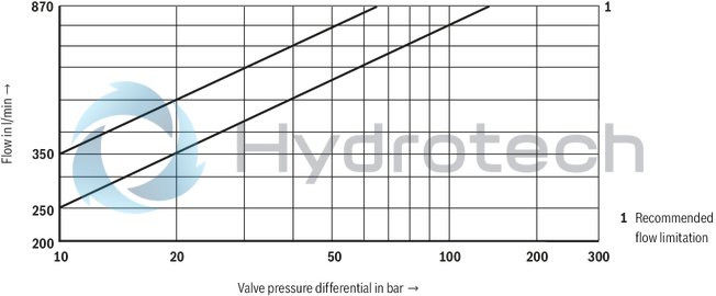
Flow/load function with maximum valve opening (tolerance ±10 %)
Size 10
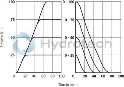
Transition function with stepped electric input signals
Size 16
Frequency response
Size 16
Flow/load function with maximum valve opening (tolerance ±10 %)
Size 16
Transition function with stepped electric input signals
NG25
Frequency response
NG25
Flow/load function with maximum valve opening (tolerance ±10 %)
NG25
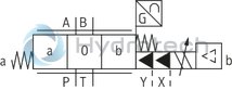
Symbols
|
Symbol E1-, V1-: |
|
|
P → A: qv P → B: qv/2 |
B → T: qv/2 A → T: qv |
|
Notice: |
|
Type 4WRGE...-1X/...
Type 4WRGE...-1X/...E...
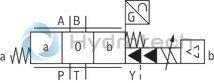
Type 4WRGE...-1X/...ET...
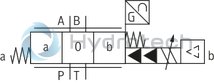
Type 4WRGE...-1X/...T...

|
Pin assignment |
Contact |
Assignment interface "A1" |
|
Supply voltage 1) |
A |
24 VDC (19 ... 35 VDC) |
|
B |
GND |
|
|
C |
n.c. |
|
|
Differential amplifier input (command value) |
D |
Command value (± 10 V / ± 10 mA) |
|
E |
Reference potential 2) |
|
|
Measuring output |
F |
Actual value (±10 V / ± 10 mA) vis-à-vis 0 V 3) |
|
PE |
Protective earthing conductor (connected directly to metal housing) |
|
|
1) |
Supply voltage +24 VDC ± 25 %; full bridge rectification with smoothing capacitor 2200 µF; Imax = 230 mA |
|
|
2) |
Current input ±10 mA → input resistance 100 Ω |
|
|
3) |
± 10 mA → maximum load resistance 1 kΩ |
|
Command value:
Positive command value at D and reference potential at E result in flow from P → A and B → T.
Negative command value at D and reference potential at E result in flow from P → B and A → T.
Connection cable:
Recommendation:
up to 25 m cable length type LiYCY 7 x 0.75 mm² up to 50 m cable length type LiYCY 7 x 1.0 mm² External diameter 6.5 … 11 mm Connect shield to PE only on the supply side.
Notice:
Electrical signals provided via control electronics (e.g. actual value) must not be used to switch off safety-relevant machine functions!
Block diagram / pin assignment
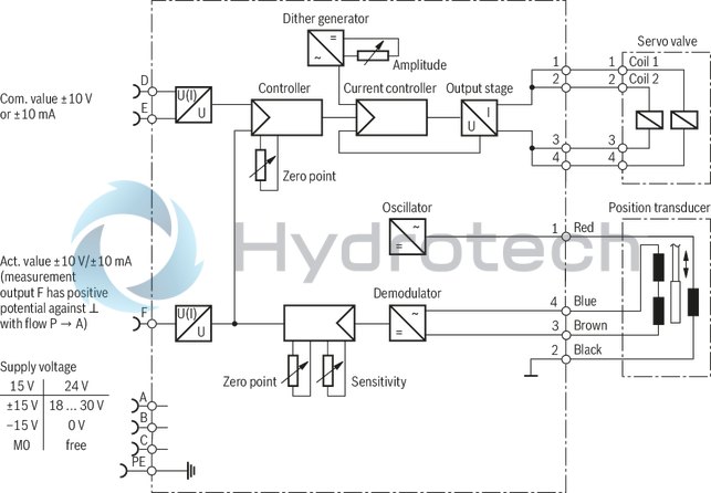
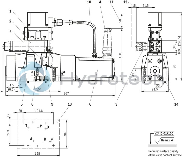
Size 10
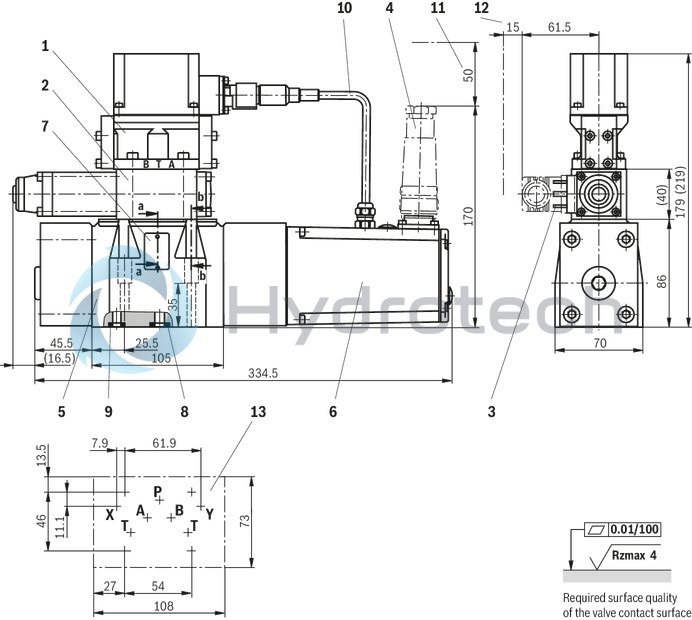
Dimensions in mm
|
1 |
Pilot control valve |
|
2 |
Directional sandwich plate valve (only included with version “WG152”) |
|
3 |
Mating connector, separate order |
|
4 |
Mating connector, separate order |
|
5 |
Main valve |
|
6 |
Integrated electronics (OBE) |
|
7 |
Name plate |
|
8 |
Identical seal rings for ports A, B, P, and T |
|
9 |
Identical seal rings for ports X and Y |
|
10 |
Cabling |
|
11 |
Space required to remove the mating connector |
|
12 |
Space required to remove the mating connector |
|
13 |
Machined valve contact surface; Porting pattern according to ISO 4401-05-05-0-05 |
Valve mounting screws (separate order):
4 hexagon socket head cap screws ISO 4762 - M6 x 45 - 10.9-flZn-240h-L
Tightening torque MA = 13.5 Nm ± 10 % , material no. R913000258
Notice:
For reasons of stability, exclusively these valve mounting screws may be used. The tightening torque of the hexagon socket head cap screws refers to maximum operating pressure!
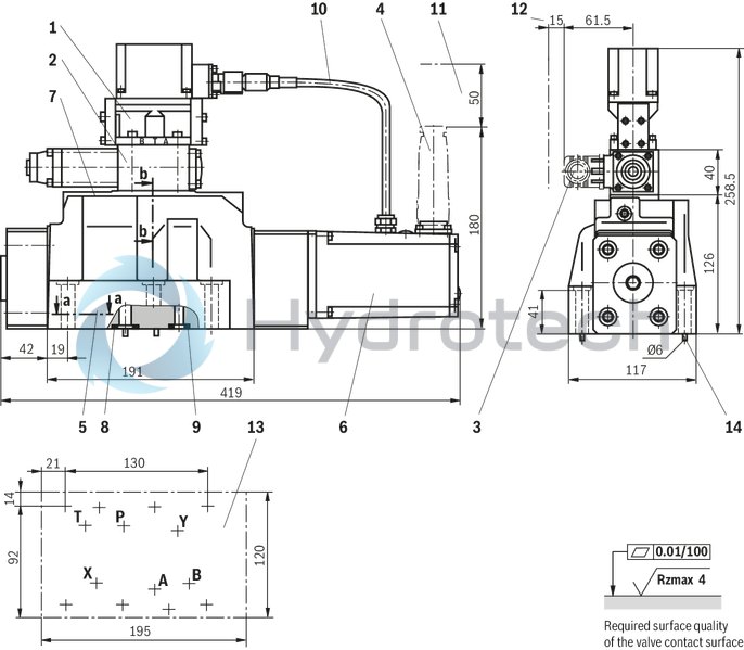
Size 16
Dimensions in mm
|
1 |
Pilot control valve |
|
2 |
Directional sandwich plate valve (only included with version “WG152”) |
|
3 |
Mating connector, separate order |
|
4 |
Mating connector, separate order |
|
5 |
Main valve |
|
6 |
Integrated electronics (OBE) |
|
7 |
Name plate |
|
8 |
Identical seal rings for ports A, B, P, and T |
|
9 |
Identical seal rings for ports X and Y |
|
10 |
Cabling |
|
11 |
Space required to remove the mating connector |
|
12 |
Space required to remove the mating connector |
|
13 |
Machined valve contact surface; Porting pattern according to ISO 4401-07-07-0-05 |
|
14 |
Locking pin |
Valve mounting screws (separate order):
2 hexagon socket head cap screws ISO 4762 - M6 x 60 - 10.9-flZn-240h-L
Tightening torque MA = 12.2 Nm ± 10 % , material no. R913000115
4 hexagon socket head cap screws ISO 4762 - M10 x 60 - 10.9-flZn-240h-L
Tightening torque MA = 58 Nm ± 20 %, material no. R913000116
Notice:
For reasons of stability, exclusively these valve mounting screws may be used. The tightening torque of the hexagon socket head cap screws refers to maximum operating pressure!
NG25
Dimensions in mm
|
1 |
Pilot control valve |
|
2 |
Directional sandwich plate valve (only included with version “WG152”) |
|
3 |
Mating connector, separate order |
|
4 |
Mating connector, separate order |
|
5 |
Main valve |
|
6 |
Integrated electronics (OBE) |
|
7 |
Name plate |
|
8 |
Identical seal rings for ports A, B, P, and T |
|
9 |
Identical seal rings for ports X and Y |
|
10 |
Cabling |
|
11 |
Space required to remove the mating connector |
|
12 |
Space required to remove the mating connector |
|
13 |
Machined valve contact surface; Porting pattern according to ISO 4401-08-08-0-05 |
|
14 |
Locking pin |
Valve mounting screws (separate order):
6 hexagon socket head cap screws ISO 4762 - M12 x 60 - 10.9-flZn-240h-L
Tightening torque MA = 100 Nm ± 20 %, material no. R913000121
Notice:
For reasons of stability, exclusively these valve mounting screws may be used. The tightening torque of the hexagon socket head cap screws refers to maximum operating pressure!
Mating connectors for valves with connector “K4”, without circuitry, standard
3P Z4
Mating connectors for valves with connector “K4”, without circuitry, standard
3P Z4
For valves with connector “K4” according to EN 175301-803 and ISO 4400, 2-pole + PE, “large cubic connector” Mating connectors for valves with one or two solenoids (individual connection)Data sheet
Spare parts & repair
Mating connectors for valves with round connector, 6-pole + PE
7P Z31
Mating connectors for valves with round connector, 6-pole + PE
7P Z31
For valves with round connector according to EN 175201-804, 6-pole + PE as well as 6-pole, compatible with VG 95328Data sheet
Spare parts & repair