
BOSCH REXROTH
ZDRS6VP-1X/50AMG24K32MG
R901025495
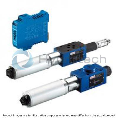
Proportional Pressure Reducing Control Valves
Prop.press.valves: DRES,ZDRES 6.-1x/
BOSCH REXROTH
MATERIAL: R901025495
SUMMARY: Prop.press.valves: DRES,ZDRES 6.-1x/
Quantity in stock: 0
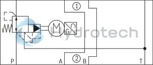
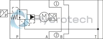
Valves of type ZDRS are pilot-operated 3-way pressure reducing valves with pressure limitation of the actuator. They are used for reducing a system pressure.
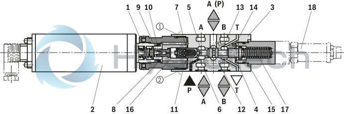
Set-up
The valves consist of three main assemblies:
Pilot control valve (1) DC motor (2) with position feedback Main valve (3) with main spool (4) Optionally with or without pressure transducer (18)
Function
Command value-dependent setting of the pressure to be reduced in channel A via the DC motor (2). In the depressurized port P, the spring (17) holds the main spool (4) in the initial position → Connection from port A to T open, port P to A blocked Pressure connection from port P to the ring channel (5). Pilot oil flows through the bore (6) via the flow controller (7) into the pilot control chamber (16), via the nozzle (8), the throttle gap (9) into chamber (10) and via bores (11; 12) to port T.
Pressure reduction
Build-up of the pilot pressure in the pilot control chamber (16) as a function of the command value. Movement of the main spool (4) to the right → hydraulic fluid flows from P to A. Actuator pressure present in port A to the spring chamber (15) via channel (13) and nozzle (14). Increase in the pressure in port A to the set command pressure leads to the movement of the main spool (4) to the left in its control position. Pressure in port A is almost identical to the set pressure at the pilot control valve (1).
Pressure limitation not possible if there is dirt.
If the pressure in port A (P1) exceeds the set command pressure, the main spool (4) is moved further to the left. This closes the connection from P to A (P1), opens the connection from P1 to T and limits the pressure present in port A(P1) according to the set command value.
Pressure monitoring
With valves with integrated pressure transducers, the transducer is connected to the electronics and is intended for the recording and monitoring of the pressure set in channel P1. Another alternative is a valve without integrated pressure transducer but with a sandwich plate for pressure measurement. (For example applications, see data sheet 62003)
Notice:
If the voltage supply of the control electronics is switched off or fails, the DC motor stops at its current position which means that, if the hydraulic supply is available, the most recently set pressure is maintained.
Type ZDRS 6 VP-1X/...
|
01 |
02 |
03 |
04 |
05 |
06 |
07 |
08 |
09 |
10 |
11 |
12 |
13 |
||
|
Z |
DRS |
6 |
VP |
‒ |
1X |
/ |
M |
G24 |
K32 |
G |
* |
|
01 |
Sandwich plate |
Z |
|
02 |
Proportional pressure reducing valve with DC motor actuation |
DRS |
|
03 |
Size 6 |
6 |
|
Pressure reduction |
||
|
04 |
In channel P (sandwich plate valve) |
VP |
|
05 |
Component series 10 ... 19 (10 ... 19: unchanged installation and connection dimensions) |
1X |
|
Pressure rating |
||
|
06 |
50 bar |
50 |
|
100 bar |
100 |
|
|
210 bar |
210 |
|
|
07 |
Without pressure transducer at the device |
A |
|
With pressure transducer at the device (version "100” only) |
S |
|
|
08 |
Without check valve |
M |
|
Supply voltage of the control electronics |
||
|
09 |
Direct voltage 24 V |
G24 |
|
Electrical connection |
||
|
10 |
Without mating connector, with connector type GO51FAVM |
K32 1) |
|
Seal material |
||
|
11 |
NBR seals |
M |
|
FKM seals |
V |
|
|
Observe compatibility of seals with hydraulic fluid used. (Other seals upon request) |
||
|
12 |
With position feedback |
G |
|
13 |
Further details in the plain text |
* |
|
1) |
Mating connector, separate order |
|
For applications outside these parameters, please consult us!
general
|
Type |
ZDRS | |
|
Size |
6 | |
|
Component series |
1X | |
|
Installation position |
any, preferably horizontal | |
|
Weight |
kg |
1.5 |
|
Storage temperature range |
°C |
-20 … +80 |
|
Ambient temperature range |
°C |
-20 … +60 |
hydraulic
|
Type |
ZDRS | ||
|
Size |
6 | ||
|
Maximum operating pressure |
bar |
210 | |
|
Maximum operating pressure |
Port P |
bar |
250 |
|
Port P1 |
bar |
210 | |
|
Port P2 |
bar |
250 | |
|
Port A |
bar |
210 | |
|
Port B |
bar |
210 | |
|
Port T 1) |
separate and depressurized to the tank (flow 30 l/min possible) | ||
|
Maximum set pressure in ports P1 and A |
Pressure rating 50 bar |
bar |
50 |
|
Pressure rating 100 bar |
bar |
100 | |
|
Pressure rating 210 bar |
bar |
210 | |
|
Minimum pressure in channel P or P➁ |
Set pressure in channel A or channel P1 plus 20 bar | ||
|
Minimum set pressure with command value 0 V in channel A or P➀ |
see characteristic curves (maximum of 3 bar) | ||
|
Pilot flow |
l/min |
0.65 | |
|
Maximum flow |
l/min |
30 | |
|
Hydraulic fluid |
see table | ||
|
Hydraulic fluid temperature range |
°C |
-20 … +80 | |
|
Viscosity range |
mm²/s |
15 … 280 | |
|
Maximum admissible degree of contamination of the hydraulic fluid, cleanliness class according to ISO 4406 (c) 2) |
Class 20/18/15 according to ISO 4406 (c) | ||
|
Hysteresis 3) |
% |
< 2 | |
|
Repetition accuracy 3) |
% |
< ± 1 | |
|
Linearity 3) |
% |
< 2 | |
|
Response sensitivity 3) |
% |
< 0.5 | |
|
Valve manufacturing tolerance of the command value pressure characteristic curve 4) |
% |
< ± 6 | |
|
Step response Tu + Tg 5) |
0 ... 100 % |
ms |
< 500 |
|
100 ... 0% |
ms |
< 500 | |
| 1) | Pressures > 10 bar may cause destruction of the motor |
| 2) | The cleanliness classes specified for the components must be adhered to in hydraulic systems. Effective filtration prevents faults and simultaneously increases the life cycle of the components. For the selection of the filters, see www.boschrexroth.com/filter. |
| 3) | Of the maximum set pressure |
| 4) |
of the maximum set pressure By zero point and range calibration in the electronics type VT-MRMA1-1-1X/V0/0, the manufacturing tolerance of the complete unit (valve + electronics) can be reduced |
| 5) | Tu + Tg measured with standing hydraulic fluid column of < 5 liters |
Notice:
The technical data were determined at a viscosity of 46 mm²/s (HLP46; 40 °C).
|
Hydraulic fluid |
Classification |
Suitable sealing materials |
Standards |
Data sheet |
|
Mineral oil |
HL, HLP |
NBR / FKM |
DIN 51524 |
90220 |
|
Bio-degradable - insoluble in water |
HEES |
FKM |
ISO 15380 |
90221 |
|
Bio-degradable - soluble in water |
HEPG |
FKM |
ISO 15380 |
|
|
Flame-resistant - water-free |
HFDU |
FKM |
ISO 12922 |
90222 |
|
Flame-resistant - containing water |
HFC (Fuchs Hydrotherm 46M, Petrofer Ultra Safe 620) |
NBR |
ISO 12922 |
90223 |
|
Important information on hydraulic fluids: For more information and data on the use of other hydraulic fluids please contact us. The flash point of the process and operating medium used must be 40 K over the maximum solenoid surface temperature. There may be limitations regarding the technical valve data (temperature, pressure range, life cycle, maintenance intervals, etc.). |
Flame-resistant - containing water: Bio-degradable: When using hydraulic fluids that are simultaneously zinc-solving, zinc may accumulate (700 mg zinc per pole tube). |
|||
electrical
|
Type |
ZDRS | ||
|
Power supply |
Nominal voltage |
V |
18 |
|
Rated current |
A |
0.5 | |
|
Rated current tolerance |
% |
± 20 | |
|
Connection resistance |
Ω |
9.9 | |
|
Maximum continuous current |
A |
0.5 | |
|
Winding temperature |
°C |
≈ 20 | |
|
K |
100 | ||
|
Protection class according to DIN EN 60529 |
IP65 (with mating connector mounted and locked) | ||
Notice:
The valves may not be used for safety-relevant machine functions since only the electrical area and not the hydraulic area is secured. This means that if the hydraulic pressure in P drops to 0 bar, the actuator pressure (A) or secondary pressure (P➀) is inevitably 0 bar as well.
When establishing the electrical connection, the protective earthing conductor (PE) has to be connected properly.
(measured with HLP46, ϑOil = 40 ±5 °C)
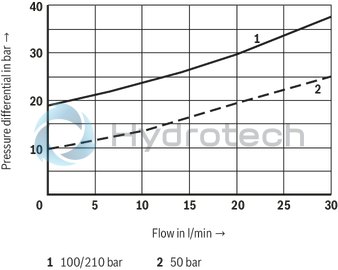
Type ZDRS (P➁ → P➀)
Type ZDRS
Notice:
The indicated pressure differential value corresponds to the minimum pressure available in port P (P➁) minus the maximum pressure to be controlled in port A (P➀).
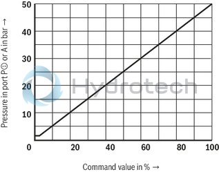
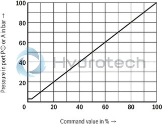
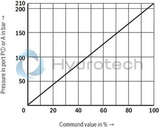
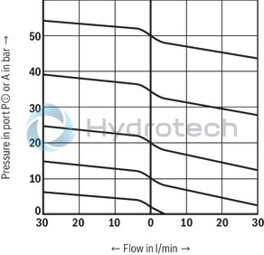
Pressure in port P➀ or A dependent on the command value
Pressure rating 50 bar
Pressure rating 100 bar
Pressure rating 210 bar
Minimum set pressure in port P➀ or A with command value 0 V
(without counter pressure in channel T or T➀)
Pressure rating 50 bar
|
P① → T② |
P② → P① |
Pressure rating 100 bar / 210 bar
|
P① → T② |
P② → P① |
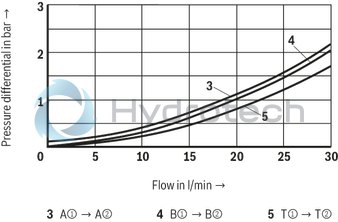
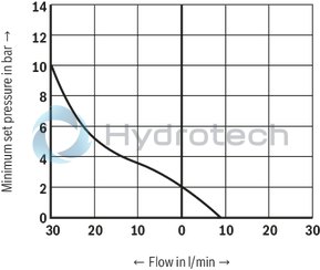
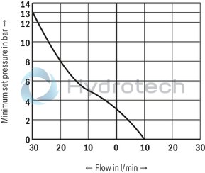
Pressure in port P➀ or A dependent on the flow
Pressure rating 50 bar
|
P① → T② |
P② → P① |
Pressure rating 100 bar
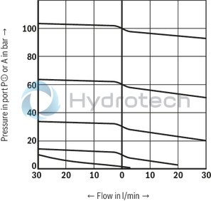
|
P① → T② |
P② → P① |
Pressure rating 210 bar
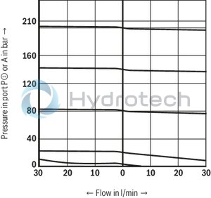
|
P① → T② |
P② → P① |
(① = component side, ② = plate side)
Version "A" (with pressure transducer)
Version “S” (with pressure transducer)
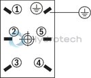
|
1 |
Position feedback + |
|
2 |
Position feedback output |
|
3 |
Position feedback - |
|
4 |
Motor + |
|
5 |
Motor - |
|
PE = GND |
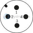
Pressure transducer at the device, version “S" (M12 plug-in connection, 4-pole; view to contact side)
|
Voltage |
Current (two-wire system) |
|
|
1 |
Auxiliary energy + (+UB) |
Auxiliary energy + (+UB) |
|
2 |
n.c. |
n.c. |
|
3 |
Auxiliary energy - (0 V) |
Auxiliary energy - (0 V) |
|
4 |
Output signal |
n.c. |
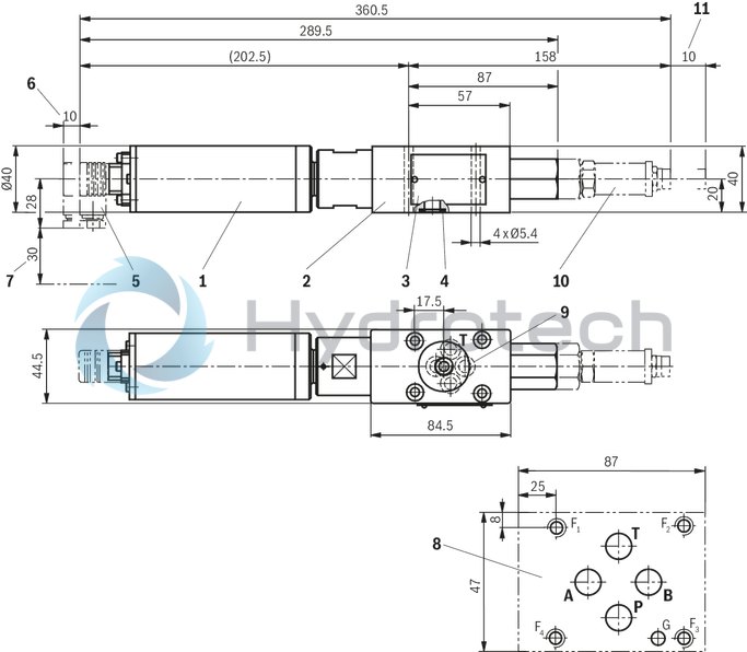
Type ZDRS
Dimensions in mm
 |
|
Required surface quality of the valve contact surface |
|
1 |
DC motor |
|
2 |
Valve housing |
|
3 |
Name plate |
|
4 |
Identical seal rings for ports A, P, T and blind counterbore B |
|
5 |
Mating connector, separate order |
|
6 |
Space required to remove the mating connector |
|
7 |
Space required for connecting cable |
|
8 |
Porting pattern according to ISO 4401-03-02-0-94 |
|
9 |
Blind counterbore (port B) |
|
10 |
Pressure transducer for type ZDRS...S |
|
11 |
Space required to remove the mating connector |
Recommended valve mounting screws (separate order):
4 hexagon socket head cap screws ISO 4762 - M5 - 10.9-flZn-240h-L
(Friction coefficient μtotal = 0.09 to 0.14)
Tightening torque MA = 7 Nm ± 10%
or
4 hexagon socket head cap screws ISO 4762 - M5 - 10.9
(Friction coefficient μtotal = 0.12 to 0.17)
Tightening torque MA = 8.1 Nm ± 10%
Notices:
The tightening torque of the hexagon socket head cap screws refers to the maximum operating pressure. Length and tightening torque of the valve mounting screws must be calculated according to the components mounted under and over the sandwich plate valve.Subplates (separate order) see data sheet 45052.
Mating connectors for sensors and valves with connector “K24”, “K35” and “K72”, M12 x 1
4P Z24
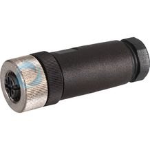
Mating connectors for sensors and valves with connector “K24”, “K35” and “K72”, M12 x 1
4P Z24
For sensors and valves with connector “K24”, “K35” and “K72” Mating connectors M12, 4-pole, line cross-section 0.75 mm2Data sheet
Spare parts & repair
Mating connectors for sensors and valves with connector “K24”, “K35” and “K72”, M12 x 1, with assembled connection line, cable shielded
4P M12 +
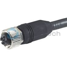
Mating connectors for sensors and valves with connector “K24”, “K35” and “K72”, M12 x 1, with assembled connection line, cable shielded
4P M12 +
For sensors and valves with connector “K24”, “K35” and “K72” Cable sets M12, 4-pole, line cross-section 0.34 mm2Data sheet
Spare parts & repair