
BOSCH REXROTH
4WE6D6X/BG24NXDZ2/V
R901034850
Directional Spool Valves
Directional spool valves: WE 6.-6x/
BOSCH REXROTH
MATERIAL: R901034850
SUMMARY: Directional spool valves: WE 6.-6x/
Due to extremely high demand, please call 888-651-5712 for availability
Directional valves of type WE are solenoid-actuated directional spool valves. They control the start, stop and direction of a fluid flow.
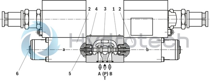
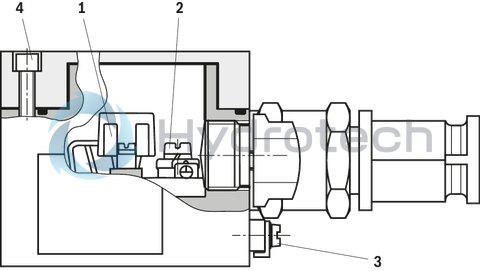
The directional valves basically consist of the housing (1), one or two solenoids (2), the control spool (3), and one or two return springs (4).
In the de-energized condition, the control spool (3) is held in the central position or in the initial position by the return springs (4) (except for impulse spools). The control spool (3) is actuated by wet-pin solenoids in hydraulic fluid (2).
To ensure proper functioning, make sure that the pressure chamber of the solenoid is filled with hydraulic fluid.
The force of the solenoid (2) acts via the plunger (5) on the control spool (3) and pushes the latter from its rest position to the required end position. This enables the necessary direction of flow from P → A and B → T or P → B and A → T.
After de-excitation of the solenoid (2), the return spring (4) pushes the control spool (3) back to its rest position.
An optional manual override (6) allows control spool (3) to be moved without solenoid energization.
Type 4WE 6.. 6X/O...XD (only possible with symbols A, C and D)
This version is a directional valve with two spool positions and two solenoids without detent. In the de-energized condition, there is no defined spool position.
Type 4WE 6.. 6X/OF... XD (impulse spool, only possible with symbols A, C and D)
This version is a directional valve with two spool positions, two solenoids and one detent. It alternately locks the two spool positions and the solenoid therefore does not need to be permanently energized.
Notice:
Pressure peaks in the tank line to two or several valves can result in unwanted movements of the control spool in the case of valves with detent! We therefore recommend that separate return lines be provided or a check valve installed in the tank line.
The tank line must not be allowed to run empty. With corresponding installation conditions, a preload valve (preload pressure approx. 2 bar [30 psi]) is to be installed.
Throttle insert (type 4WE 6..6X/…XD../B.. )
The use of a throttle insert is required when due to prevailing operating conditions, flows can occur during the switching processes, which exceed the performance limit of the valve.
It is inserted in channel P of the directional valve.
Type 4WE 6 E6X/.B..NXDZ2/V
|
01 |
02 |
03 |
04 |
05 |
06 |
07 |
08 |
09 |
10 |
11 |
12 |
|||
|
WE |
6 |
6X |
/ |
B |
N |
XD |
Z2 |
/ |
|
01 |
3 main ports |
3 |
|
4 main ports |
4 |
|
|
02 |
Size 6 |
6 |
|
03 |
Control spool symbol e. g. C, E, EA, EB etc. possible versions see Symbols |
|
|
04 |
Component series 60 … 69 (60 … 69: unchanged installation and connection dimensions) |
6X |
|
05 |
Spring return |
no code |
|
Without spring return |
O |
|
|
Without spring return with detent |
OF |
|
|
06 |
High-power solenoid (wet-pin in hydraulic fluid) |
B |
|
07 |
Direct voltage 24 V |
G24 |
|
Direct voltage 110 V |
G110 |
|
|
08 |
with manual override (standard) |
N |
|
09 |
“Flameproof enclosure” explosion protection, for details please refer to the explosion protection information |
XD |
|
Electrical connection |
||
|
10 |
Solenoid with terminal box and cable gland; for details please refer to "Electrical connection" |
Z2 |
|
11 |
Without throttle insert |
no code |
|
Throttle Ø 0,8 mm |
B08 |
|
|
Throttle Ø 1,0 mm |
B10 |
|
|
Throttle Ø 1.2 mm |
B12 |
|
|
Use if flow > performance limit of the valve |
||
|
12 |
NBR seals |
no code |
|
FKM seals |
V |
|
|
Observe compatibility of seals with hydraulic fluid used. |
||
included in the scope of delivery:
Valve operating instructions with declaration of conformity in part III
general
|
Size |
6 | ||
|
Weight |
Valve with one solenoid |
kg |
5.3 |
|
Valve with two solenoids |
kg |
9.4 | |
|
Installation position |
any | ||
|
Ambient temperature range |
°C |
-20 … +80 | |
|
Storage temperature range |
°C |
+15 … +30 | |
|
Admissible vibration load 1) |
Hz |
20 ... 2.000 | |
|
Surface protection |
Valve body |
Fe//ZnNi8//Cn//T0 | |
|
Solenoid |
Fe//ZnNi8//An//T0 | ||
|
Thermal conductivity of the subplate (EN-GJS-500-7) |
W/m K |
≥ 38 | |
| 1) | Amplitude 0.05 g2/Hz (10 g RMS) |
|
Hydraulic fluid |
Classification |
Suitable sealing materials |
Standards |
|
|
Mineral oil |
HL, HLP |
FKM, NBR |
DIN 51524 |
|
|
Bio-degradable |
Insoluble in water |
HEES (synthetic esters) |
FKM |
VDMA 24568 |
|
HETG (rape seed oil) |
FKM, NBR |
|||
|
Soluble in water |
HEPG (polyglycols) |
FKM |
VDMA 24568 |
|
|
Containing water |
Containing water |
HFC 1) |
NBR |
ISO 12922 |
|
Ignition temperature > 180 °C |
||||
| 1) If HFC hydraulic fluid is used, the following parameters have to be complied with: | |
| Pressure at P, A, B max. 160 bar, at T max. 3 bar | |
| Ambient temperature 0 … 36 °C | |
| Hydraulic fluid temperature max. 55 °C | |
| Duty cycle 60% | |
| Only NBR seals are admissible. | |
| More information is available from our sales staff. |
electrical
|
Voltage type |
Direct voltage | ||
|
Available voltages |
24 V / 110 V | ||
|
Voltage tolerance (nominal voltage) |
% |
± 10 | |
|
Admissible residual ripple |
% |
< 5 | |
|
Duty cycle 1) |
% |
100 | |
|
Switching time according to ISO 6403 |
ON |
ms |
30 … 70 |
|
OFF |
ms |
20 … 30 | |
|
Maximum switching frequency |
1/h |
15000 | |
|
Nominal power with ambient temperature 20 °C |
W |
13 | |
|
Maximum power with 1.1 x nominal voltage and an ambient temperature of 20 °C |
W |
15.8 | |
|
Protection class according to DIN EN 60529 2) |
IP65 | ||
| 1) | Operating mode according to VDE 0580 |
| 2) | With correctly installed electrical connection |
Information on explosion protection
|
Area of application according to directive 2014/34/EU |
I M2; II 2G | |
|
Type of protection valve |
c (EN 13463-5) | |
|
Maximum surface temperature 1) |
°C |
130 |
|
Temperature class |
T4 | |
|
Type of protection of solenoid according to EN 60079-0:2009 / EN 60079-1:2007 |
Ex d I Mb, Ex d IIC T4 Gb | |
|
Baumusterprüfbescheinigung Magnet |
BVS 03 ATEX E 300 X | |
| 1) | Surface temperature > 50 °C, provide contact protection. |
Special conditions for safe use
In case of bank assembly, only one solenoid of all valves may be energized at a time. In case of valves with two solenoids, maximally one of the solenoids may be energized at a time.hydraulic
|
Size |
6 | ||
|
Maximum surface temperature |
see Information on explosion protection | ||
|
Maximum operating pressure |
Port P |
bar |
315 |
|
Port A |
bar |
315 | |
|
Port B |
bar |
315 | |
|
Port T 1) |
bar |
210 | |
|
Maximum flow |
l/min |
60 | |
|
Flow cross-section (spool position 0) |
Symbol Q |
approx. 6 % of nominal cross-section | |
|
Symbol W |
approx. 3 % of nominal cross-section | ||
|
Hydraulic fluid |
see table | ||
|
Hydraulic fluid temperature range |
NBR seals |
°C |
-20 … +80 |
|
FKM seals |
°C |
-15 … +80 | |
|
Viscosity range |
mm²/s |
2,8 … 500 | |
|
Maximum admissible degree of contamination of the hydraulic fluid 2) |
Class 20/18/15 according to ISO 4406 (c) | ||
| 1) | With symbols A and B, port T must be used as leakage oil connection if the operating pressure exceeds the admissible tank pressure. |
| 2) | The cleanliness classes specified for the components must be adhered to in hydraulic systems. Effective filtration prevents faults and simultaneously increases the life cycle of the components. For the selection of the filters, see www.boschrexroth.com/filter. |
For applications outside these parameters, please consult us!
Performance limits
(measured with HLP46, ϑOil = 40 ±5 °C)
Notice
The specified switching power limits are valid for use with two directions of flow (e. g. from P → A and simultaneous return flow from B → T).
Due to the flow forces acting within the valves, the admissible switching power limit may be considerably lower with only one direction of flow (e. g. from P → A while port B is blocked)!
(In such use cases, please consult us.)
The switching power limits were established while the solenoids were at operating temperature, at 10 % undervoltage and without tank preloading.
Performance limits of the valves with DC solenoids
|
Characteristic curve |
Symbol |
|
1 |
A, B |
|
2 |
J, L, U |
|
3 |
V |
|
4 |
F, P |
|
5 |
A/O, A/OF |
|
6 |
G |
|
7 |
T |
|
8 |
R 2) |
|
9 |
E |
|
10 |
Q, W |
|
11 |
D, C, Y, Y2 |
|
12 |
H |
|
13 |
M |
|
14 |
E1 1), D/OF, C/OF, D/O, C/O |
|
15 |
B9 |
|
16 |
B9 SO9 |
|
17 |
H19 |
|
18 |
J19, P–A |
|
19 |
J,19 A–T |
|
20 |
J19, B–T |
|
21 |
X36A |
|
22 |
D9 |
|
23 |
E41 |
| 1) P–A/B pre-opening | |
| 2) Return flow from actuator to tank |
(measured with HLP46, ϑOil = 40 ±5 °C) and p = 100 bar)
Δp-qV characteristic curves
|
Characteristic curve selection |
||||||
|
Symbol |
Direction of flow |
|||||
|
P – A |
P – B |
A – T |
B – T |
B – A |
P – T |
|
|
A, B |
3 |
3 |
– |
– |
– |
– |
|
C |
1 |
1 |
3 |
1 |
– |
– |
|
D, Y, Y2 |
5 |
5 |
3 |
3 |
– |
– |
|
E |
3 |
3 |
1 |
1 |
– |
– |
|
F |
1 |
3 |
1 |
1 |
– |
– |
|
T |
10 |
10 |
9 |
9 |
– |
8 |
|
H |
2 |
4 |
2 |
2 |
– |
9 |
|
J, Q |
1 |
1 |
2 |
1 |
– |
– |
|
L |
3 |
3 |
4 |
9 |
– |
– |
|
M |
2 |
4 |
3 |
3 |
– |
– |
|
P |
3 |
1 |
1 |
1 |
– |
– |
|
R |
5 |
5 |
4 |
– |
7 |
– |
|
V |
1 |
2 |
1 |
1 |
– |
– |
|
W |
1 |
1 |
2 |
2 |
– |
– |
|
U |
3 |
3 |
9 |
4 |
– |
– |
|
G |
6 |
6 |
9 |
9 |
– |
8 |
|
B9 |
11 |
11 |
– |
– |
– |
– |
|
B9 SO9 |
12 |
11 |
– |
– |
– |
– |
|
H19 |
14 |
14 |
13 |
13 |
15 |
– |
|
J19 |
14 |
– |
16 |
13 |
– |
– |
|
X36A |
17 |
– |
18 |
19 |
– |
– |
|
D9 |
8 |
20 |
8 |
15 |
– |
– |
|
E41 |
20 |
20 |
8 |
8 |
– |
– |
Δp-qV characteristic curves
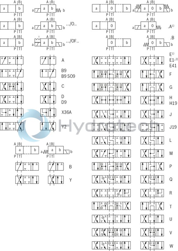
| 1) | Example: Control spool E with spool position „a“, ordering code ..EA.. |
| 2) | Symbol E1-: P → A/B pre-opening, Caution in conjunction with differential cylinders due to pressure intensification! |
The type-examination tested valve solenoid of the valve is equipped with a terminal box and a type-tested cable entry.
The connection is polarity-independent.
Notice
When establishing the electrical connection, the protective earthing conductor (PE) has to be connected properly.
|
Properties of the connection terminals and mounting elements |
||
|
Position |
Function |
Connectable line cross-section |
|
1 |
Operating voltage connection |
Single-wire 2.5 mm2 max. Finely stranded, max. 2.5 mm2 |
|
2 |
Connection for protective earthing conductor |
Single-wire 0.75 … 2.5 mm2 Finely stranded,0.75 … 1.5 mm2 |
|
3 |
Connection for potential equalization conductor |
Single-wired, 4 … 6 mm2 Finely stranded, min. 4 mm2 |
|
4 |
Screws for cover |
– |
|
Cable gland |
Line diameter |
mm |
9 ... 12 |
|
Sealing |
Outer sheath sealing | ||
|
Connection line |
Line type |
Non-armored cables and lines (outer sheath sealing) | |
|
Temperature range |
°C |
-20 … +110 |
Circuit diagrams
Direct voltage, polarity-independent
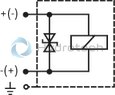
Over-current fuse and switch-off voltage peak
Notice
A fuse appropriate for the solenoid's rated current (max. 3 x Irated according to DIN 41571 and/or IEC 60127) or a protective motor switch with short-circuit protection and thermal instantaneous tripping must be connected upstream of each valve solenoid as short-circuit protection. The shut-off threshold of this fuse must match or exceed the short-circuit current of the supply source.
This fuse or protective motor switch may only be fitted outside the potentially explosive area or must be of an explosion-proof design.
When inductivities are switched off, voltage peaks result which may cause faults in the connected control electronics. For this reason, the valve solenoids comprise an interference protection circuit which dampens this voltage peak to the voltage value shown in the table.
|
Voltage data in the valve type code |
Nominal voltage valve solenoid |
Rated current valve solenoid |
Recommended pre-fuse characteristic: medium time-lag according to DIN 41571 |
Maximum voltage value when switching off |
Interference protection circuit |
|
G24 |
24 V DC |
0,542 A DC |
630 mA |
–90 V |
Suppressor diode bi-directional |
|
G110 |
110 V DC |
0,118 A DC |
125 mA |
–390 V |
Valve with manual override "N"
Dimensions in mm
|
1 |
Solenoid |
|
2 |
Terminal box |
|
3 |
Manual override "N" |
|
4 |
Identical seal rings for ports P, A, B, T |
|
5 |
Plug screw for valves with one solenoid |
|
6 |
Name plate |
|
7 |
Receiving hole for locating pin according to ISO 4401-03-02-0-05, locating pin mat. no. R900005694 (has to be ordered separately) |
|
8 |
Porting pattern according to ISO 4401-03-02-0-05 |
Valve mounting screws
For reasons of stability, exclusively the following valve mounting screws are to be used:
4 hexagon socket head cap screws
ISO 4762-M5x50-10.9-flZn-240h-L
(friction coefficient 0.09 - 0.14 according to VDA 235-101)
Material no. R913000064 (must be ordered separately)
Subplates
(without locating hole)
G 341/01 FE/ZN (G1/4)
G 342/01 FE/ZN (G3/8)
G 502/01 FE/ZN (G1/2)
(with locating hole)
G 341/60 FE/ZN (G1/4)
G 342/60 FE/ZN (G3/8)
G 502/60 FE/ZN (G1/2)
with dimensions as in the data sheet 45052 (must be ordered separately)
Notice:
In case of bank assembly, only one solenoid of all valves may be energized at a time.
Notice:
Subplates are no components in the sense of directive 94/9/EC and can be used after an assessment of the risk of ignition by the manufacturer of the overall system.
The G...FE/ZN versions are free from aluminum and/or free from magnesium and galvanized.
Installation conditions
Schematic diagram
Dimensions in mm
Notice:
In case of bank assembly, only one solenoid of all valves may be energized at a time.
Notice:
Subplates are no components in the sense of directive 94/9/EC and can be used after an assessment of the risk of ignition by the manufacturer of the overall system.
The G...FE/ZN versions are free from aluminum and/or free from magnesium and galvanized.