
BOSCH REXROTH
VT-VRPD-2-2X/V0/0-0-1
R901066987
Valve Amplifiers
Spare- a. Singleparts Electronic
BOSCH REXROTH
MATERIAL: R901066987
SUMMARY: Spare- a. Singleparts Electronic
Quantity in stock: 0
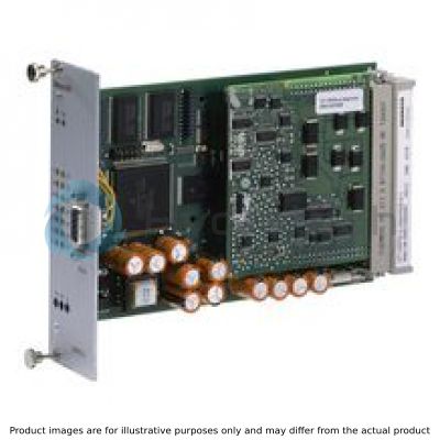
The valve amplifier is set-up as printed circuit board in Europe format 100 mm x 160 mm with daughter board, fitted on both sides.
The central unit is a microcontroller controlling the entire process and realizing the position control. Data for configuration, command values and parameters are stored in a FLASH in a non-volatile form.
Four binarily coded digital inputs are used to call up parameter sets (command values) from the memory in which you can store a maximum of 16 sets. A call-up activates the command value for the control spool position with the related ramp times.
More control inputs have the following functions:
Command value valid:
Enabling of the parameter set addressed by the current call-up (H active)
Enable:
Activation of the outputs (acknowledgment of the fault message with low→high edge)
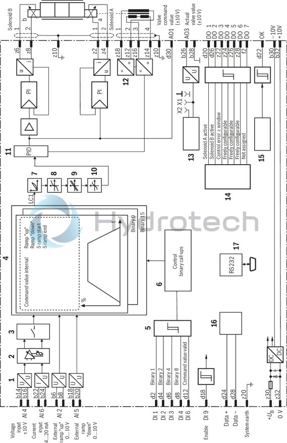
The valve amplifier comprises a controller for the control spool position of a proportional valve.
The command value can be preset via digital command value call-ups [5] and/or via analog inputs [1]. The analog input AI4 (b14/b16) is to be used for the command value presetting of ±10 V, the analog input AI6 (b22/b24) for any command value presetting from 4 to 20 mA.
Command values from 0 to +10 V (12...20 mA) control solenoid B.
Command values from 0 to –10 V (4...12 mA) control solenoid A.
The digital command value is added to the analog command value with the correct sign, according to the set call-up.
The command value inputs can be varied by means of software in the signal level.
Apart from the internal ramp generation option, you can also influence the ramp for "up" and "down" from external signals with correct total and correct sign by means of the AI2 (b6/b8) and AI5 (b18/b20) analog inputs.
For the valves, the software configures a step function generator [8] for the realization of the overlap jump if an overlapped control spool is selected.
The command value total is switched to the controller [12]. The actual valve value (b26) is generated from the valve position measurement system by means of an oscillator/a demodulator stage and also switched to the controller [12]. The controller output controls the flow-controlled output stages.
Enable and error messages
The control is activated by the H level at the enable input. If no command value call-up is active, the digital call-up 0 is set.
Error logics [15] identify any control deviation, cable break of the actual value cables and the command value input for 4 to 20 mA as well as an inactive enable input. If there is an error, a fault message is output to (d22) by means of a low signal and indicated visually by the "OK" LED (LED goes out) on the front plate. It is possible to configure the enable so that an inactive enable input is not indicated as error.
Parameterization and diagnosis
Selection of the valve to be controlled and selection and configuration of the command value input, the ramp generator and the enable input as well as the setting of the command value call-up parameters are effected via the serial interface [17] at the front-side D-Sub socket. Via the local bus [16], up to 32 valve amplifiers can be connected. Via BODAC, every valve amplifier is assigned a bus address. Reconnection of the serial interface cable is not required. Further information in instructions 30126-01-B.
[ ] = Assignment to the block diagram
|
01 |
Digital valve amplifier for proportional directional valves with electrical position feedback |
VT-VRPD |
|
02 |
For valves: 4WRE 6...2X, 4WRE 10...2X |
2 |
|
03 |
Component series 20 ... 29 (20 ... 29: unchanged technical data and pin assignment) |
2X |
|
04 |
Version: standard |
V0 |
|
05 |
Without display |
0 |
|
06 |
Option: standard |
0 |
|
07 |
With valve output stage (Only suitable for valves with two solenoids) |
1 |
|
01 |
02 |
03 |
04 |
05 |
06 |
07 |
||||||
|
VT-VRPD |
‒ |
2 |
‒ |
2X |
/ |
V0 |
/ |
0 |
‒ |
0 |
‒ |
1 |
General
|
Component series |
2X | |
|
Type of electronics |
Digital | |
|
Design |
Euro-card |
Voltage supply
|
Operating voltage |
normal |
U |
V |
24 |
|
Lower limit value |
UB(t)min |
V |
21 | |
|
Upper limit value |
UB(t)max |
V |
30 | |
|
Current consumption |
max. |
Imax |
A |
1.5 |
|
Standby current |
mA |
270 | ||
|
Fuse |
4 A time-lag | |||
Analog inputs
|
Command value |
Voltage inputs |
Number and designation |
3 (AI2, AI4, AI5) | ||
|
Voltage (differential input) |
U |
V |
0 ... 10 | ||
|
Input resistance |
R |
kΩ |
≥ 100 | ||
|
Voltage |
Input resistance |
AI2 |
R |
MΩ |
10 |
|
Resolution for ± 10 |
mV |
5 | |||
|
Resolution for 0...10 |
mV |
2.5 | |||
|
Non-linearity |
mV |
< 10 | |||
|
Current |
Command value |
I |
mA |
4 … 20 | |
|
Input resistance |
R |
Ω |
100 | ||
|
Resolution |
μA |
5 | |||
|
Leakage current |
0.15 (at 500 Ω between pin b24 and 0 V) | ||||
|
Parameter sets |
Quantity |
callable command values |
16 | ||
Digital inputs
|
Digital inputs |
Number and designation |
4/16 | ||
|
Signal |
log 0 |
0 ... 5 | ||
|
log 1 |
16 ... UB | |||
Analog outputs
|
Voltage |
% |
0 … 10 | |
|
Load resistance |
1 | ||
|
Resolution |
1.25 (14 bit) | ||
|
Residual ripple |
±15 (without noise) |
Digital outputs
|
Digital outputs |
Signal |
log 1 1) |
UB - 3V | |
|
log 0 |
0 ... 5 |
| 1) | Imax = 30 mA, short-circuit-proof |
Solenoid outputs
|
Solenoid current |
max. |
Imax |
A |
2.5 |
Digital outputs
|
Oscillator frequency |
U |
V |
5.7 |
Adjustment options
|
Ramp time up/down |
Ramp 1 |
t |
s |
0 … 300 |
Displays
|
LED display |
Green |
Ready for operation | |
|
Yellow |
Enable |
Supplementary information
|
Reference voltage |
Potentiometer supply |
U |
V |
±10 (Imax = 30 mA) |
|
Residual ripple |
mV |
20 | ||
|
Scanning time |
Command value preparation |
ms |
2 | |
|
Serial interface |
RS 232, D-Sub socket | |||
|
Local bus |
Distance to the furthermost device |
32/maximum 280 m line length | ||
|
Anschlussart |
64-pin male connector, DIN 41612, form G | |||
|
Ambient temperature range |
ϑ |
°C |
0 … 50 | |
|
Storage temperature range |
ϑ |
°C |
-20 … 70 | |
|
Weight |
m |
kg |
0.2 | |
Peripherals, system information
|
Current consumption per solenoid |
max. |
Imax |
A |
2.5 |
|
Solenoid coil resistance |
Cold value at 20 °C |
R |
Ω |
2.7 |
|
at maximum hot value |
R |
Ω |
4.5 | |
|
Position transducer carrier frequency |
f |
kHz |
5.7 | |
|
Position transducer coil resistance |
at 20 °C port 1 + 2 |
R |
Ω |
113 |
|
at 20 °C port 3 + 4 |
R |
Ω |
101 | |
For applications outside these parameters, please consult us!
Notice:
For information on environment simulation testing for the fields EMC (electro-magnetic compatibility), climate and mechanical load, see data sheet 30126.
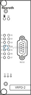
LED displays
|
|
Enable activated |
|
OK |
Ready for operation |
|
I1 … I4 |
Binary command value call-ups |
|
I5, I7 |
not assigned |
|
I6 |
Command value valid |
|
O1 |
Solenoid A active |
|
O2 |
Solenoid B active |
|
O3 |
Closed-loop error ≥ Window |
|
O4 … O6 |
Freely configurable |
|
O7 |
not assigned |
Measuring sockets
|
X1 |
actual valve position value |
|
X2 |
Valve position command value (Default) |
|
⊥ |
Reference potential 0 V |
|
1 |
U/U or I/U transformer |
|
2 |
Analog input adjustment |
|
3 |
Switching matrix |
|
4 |
Command value generation |
|
5 |
Binary command value call-ups |
|
6 |
Control of the binary call-ups |
|
7 |
Characteristic curve adjustment |
|
8 |
Step function generator |
|
9 |
Offset |
|
10 |
Amplitude limiter |
|
11 |
PID controller |
|
12 |
Oscillator/demodulator |
|
13 |
Measuring sockets |
|
14 |
Digital outputs |
|
15 |
Error logics |
|
16 |
Local bus |
|
17 |
Serial interface |
|
X1, X2, ⊥ |
See Operating and display elements |
Pin assignment of the male multipoint connector
|
Row d |
Row b |
|||||
|
Pin |
Signal |
Description |
Pin |
Signal |
Description |
|
|
2 |
DI1 |
Binary command value call-up 1 |
2 |
n. c. |
not assigned |
|
|
4 |
DI2 |
Binary command value call-up 2 |
4 |
n. c. |
not assigned |
|
|
6 |
DI3 |
Binary command value call-up 4 |
6 |
AI2+ |
Ramp+ (U/I)+ |
|
|
8 |
DI4 |
Binary command value call-up 8 |
8 |
AI2- |
Ramp+ (U/I)- |
|
|
10 |
DI5 |
not assigned |
10 |
n. c. |
not assigned |
|
|
12 |
DI6 |
Command value valid |
12 |
n. c. |
not assigned |
|
|
14 |
DI7 |
not assigned |
14 |
AI4+ |
Command value (U)+ |
|
|
16 |
DI8 |
not assigned |
16 |
AI4- |
Command value (U)- |
|
|
18 |
DI9 |
Enable |
18 |
AI5+ |
Ramp- (U/I)+ |
|
|
20 |
DO1 |
Solenoid A active |
20 |
AI5- |
Ramp- (U/I)- |
|
|
22 |
OK |
OK output |
22 |
AI6+ |
Command value (I)+ |
|
|
24 |
Data+ |
Local bus |
24 |
AI6- |
Command value (I)- |
|
|
26 |
DO2 |
Solenoid B active |
26 |
AO3 |
Actual valve position value (±10 V) |
|
|
28 |
Data- |
Local bus |
28 |
AGND |
Analog GND |
|
|
30 |
AO1 |
Valve position command value |
30 |
REF- |
-10 V |
|
|
32 |
n. c. |
not assigned |
32 |
REF+ |
+10 V |
|
|
Row z |
Row f |
|||||
|
Pin |
Signal |
Description |
Pin |
Signal |
Description |
|
|
2 |
MA+ |
Solenoid A+ |
2 |
DO7 |
not assigned |
|
|
4 |
MA- |
Solenoid A- |
4 |
n. c. |
not assigned |
|
|
6 |
MB+ |
Solenoid B+ |
6 |
n. c. |
not assigned |
|
|
8 |
MB- |
Solenoid B- |
8 |
n. c. |
not assigned |
|
|
10 |
Shield |
Shield |
10 |
n. c. |
not assigned |
|
|
12 |
L1O- |
Position transducer of valve, feed -, pin 2 |
12 |
n. c. |
not assigned |
|
|
14 |
L1I- |
Position transducer of valve, actual value –, pin 4 |
14 |
n. c. |
not assigned |
|
|
16 |
L1I+ |
Position transducer of valve, actual value +, pin 3 |
16 |
n. c. |
not assigned |
|
|
18 |
L1O+ |
Position transducer of valve, feed +, pin 1 |
18 |
n. c. |
not assigned |
|
|
20 |
System earth |
System earth |
20 |
n. c. |
not assigned |
|
|
22 |
DO3 |
Closed-loop error ≥ Window |
22 |
n. c. |
not assigned |
|
|
24 |
DO4 |
Freely configurable |
24 |
n. c. |
not assigned |
|
|
26 |
DO5 |
Freely configurable |
26 |
n. c. |
not assigned |
|
|
28 |
DO6 |
Freely configurable |
28 |
n. c. |
not assigned |
|
|
30 |
UB |
Operating voltage |
30 |
n. c. |
not assigned |
|
|
32 |
L0 |
Ground 0 V |
32 |
n. c. |
not assigned |
|
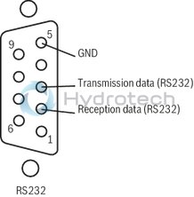
Pin assignment of the RS 232 socket
Type M-.SMM…
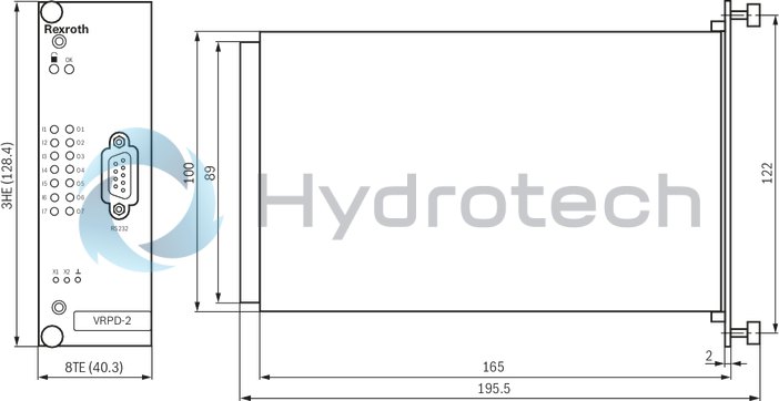
Dimensions in mm

Dimensions in mm
The amplifier card may only be unplugged and plugged when de-energized.
No connectors with free-wheeling diodes or LED displays must be used for solenoid connection.
Only carry out measurements at the card using instruments Ri > 100 kΩ.
For switching command values, relays with gold-plated contacts have to be used (low voltages, low currents).
Always shield command value lines and lead them separately; connect shielding to connection z10 on the card-side, other side open (danger of ground loops).
For solenoid conductors up to 50 m in length, use the line type LiYCY 1.5 mm2. For greater lengths, please contact us. Shield the solenoid conductors.
Use highly flexible Cu conductors (at least 2.5 mm2) to connect the system earth.
The system earth is a main part of the EMC protection of the amplifier card. It is intended to eliminate interferences which are transported via the data and supply lines. However, this is only possible if the system earth itself does not introduce interferences into the command value card.
The distance to aerial lines, radios, and radar systems has to be at least 1 m.
Do not lay solenoid conductors and signal lines near power lines.
The charging power of the smoothing capacitor on the card requires the pre-fuses to be of a slow-blowing characteristic.
Notice:
If a differential input is used, both inputs must always be connected or disconnected simultaneously.