
BOSCH REXROTH
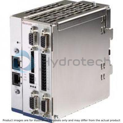
VT-HNC100-C-3X/S-S-00/000
R901112919
Controller Test Rigs
Digital controller HNC 3X
BOSCH REXROTH
MATERIAL: R901112919
SUMMARY: Digital controller HNC 3X
Due to extremely high demand, please call 888-651-5712 for availability
|
01 |
02 |
03 |
04 |
05 |
06 |
07 |
||||||
|
VT-HNC100 |
– |
– |
3X |
/ |
S |
– |
– |
/ |
|
01 |
Serial unit |
VT-HNC100 |
|
Versions for an hydraulic axis |
||
|
02 |
Compact |
C |
|
Standard |
1 |
|
|
03 |
Component series 30 ... 39 (30 ... 39: unchanged technical data and pin assignment) |
3X |
|
Bus connection |
||
|
04 |
sercos II / sercos III 1) |
S |
|
Position transducer |
||
|
05 |
Incremental/EnDat 2.2/SSI (standard) 2) |
I |
|
EnDat 2.2/SSI (only in connection with Compact version) 2) |
S |
|
|
06 |
sercos II (only in connection with Compact version) |
00 |
|
sercos III (only in connection with Standard version) |
30 |
|
|
07 |
Option |
E |
|
Without |
000 |
|
| 1) Ethernet service interface only in connection with sercos III | |
| 2) Can be selected by means of the IndraWorks PC program |
General
|
Component series |
3X |
Analog inputs (AI)
|
Voltage input (reference to AGND - Analog ground) |
Channel number |
1 | ||
|
Input voltage |
UE |
max. +12 V to –12 V (+10 V to –10 V measurable) | ||
|
Input resistance |
RE |
200 kΩ ± 5 % | ||
|
Resolution |
5 mV | |||
|
Non-linearity |
% |
< 0.2 | ||
|
Calibration tolerance, max. 1) |
40 mV (with factory settings) | |||
|
Current inputs |
Channel number |
2 | ||
|
Input current |
IE |
4 mA to 20 mA | ||
|
Leakage current |
Iv |
0.1 to 0.4 % (with 100 Ω between pin 2 or pin 3 (Cin1+ or Cin2+) and "AGND" | ||
|
Resolution |
5 μA | |||
|
Voltage supply for analog sensors via VT-HNC100-C-3X/S |
U, I |
UB, max. 100 mA at X2A, pin 7 (+24 Vsens) | ||
| 1) | If the factory settings are insufficient, the measurement technology can be calibrated on site via software in a system-specific way. |
Digital inputs (DI)
|
Switching inputs (DI) |
Number |
4 | |
|
Logic level |
log 0 (low) ≤ 5 V; log 1 (high) ≥ 10 V to UB, Ie = 20 mA at UB = 24 V | ||
|
Connection |
flexible conductor up to 1.5 mm2 | ||
|
Reference potential for all signals |
DGND |
Digital outputs (DO)
|
Switching outputs (DO) |
Number |
2 | |
|
Logic level |
log 0 (low) ≤ 2 V; log 1 (high) ≤ UB; Imax = 20 mA, maximum load capacity C = 0.047 μF | ||
|
Connection |
flexible conductor up to 1.5 mm2 | ||
|
Reference potential for all signals |
DGND |
Digital position transducers (encoders):
|
SSI transducer 1) |
Coding |
Gray code / binary code | ||
|
Data width |
adjustable 12 to 28 bits | |||
|
Line receiver/driver |
RS485 | |||
|
Voltage supply via VT-HNC100-C-3X/S |
U, I |
UB, max. 200 mA an X8M, pin 7 (+24 Venc) | ||
|
Position transducer, EnDat 2.2 |
Interface (clock and data) |
RS485 | ||
|
Voltage supply via VT-HNC100-C-3X/S |
U, I |
5.25 V ±1 %, max. 400 mA at X8M, pin 6 (+5 Venc) 3.6 to 5.25 V must be applied to the encoder. | ||
|
Resolution |
minimum 10 nm or higher | |||
|
Reference potential for all signals |
EGND | |||
| 1) | Due to the higher control quality, an SSI transducer with clock synchronization should be used |
Other information
|
Processor |
32 bit power PC | ||
|
Bus interface |
sercos II | ||
|
Installation |
Top hat rail TH 35-7.5 or TH 35-15 according to EN 60715 | ||
|
Admissible operating temperature range |
ϑ |
°C |
0 … +50 |
|
Storage temperature range |
ϑ |
°C |
-20 … +70 |
|
Protection class according to EN 60529:1991 |
Uref |
IP 20 | |
|
Weight |
m |
g |
440 |
|
CE conformity |
See features |
General
|
Component series |
3X |
Voltage supply
|
Operating voltage 1) |
UB |
18 to 30 VDC | |
|
Current consumption at 24 VDC |
CPU card approx. 200 mA per axis approx. 100 mA (observe additional current consumption for connected sensors/actuators) |
| 1) | If a 24 V encoder supply is implemented directly via the VT-HNC100-1-3X/S (supply voltage is looped in), the encoder specification has to be observed. |
Analog inputs (AI) per axis electronics
|
Voltage inputs (differential inputs) |
Channel number |
2 | ||
|
Input voltage |
UE |
max. +12 V to –12 V (+10 V to –10 V measurable) | ||
|
Input resistance |
Re |
200 kΩ ± 5 % | ||
|
Resolution |
5 mV | |||
|
Non-linearity |
% |
< 0.2 | ||
|
Calibration tolerance, max. 1) |
40 mV (with factory settings) | |||
|
Current inputs |
Channel number |
2 | ||
|
Input current |
Ie |
4 mA to 20 mA | ||
|
Leakage current |
Iv |
0.1 to 0.4 % | ||
|
Resolution |
5 μA | |||
|
Voltage supply for analog sensors via VT-HNC100-1-3X/S |
U, I |
UB, max. 200 mA at X2A, Pin 14 (+24 Vsens) | ||
| 1) | If the factory settings are insufficient, the measurement technology can be calibrated on site via software in a system-specific way. |
Digital inputs
|
Switching inputs (DI) per axis electronics (adjustable via software) |
Number |
11 | |
|
Switching inputs (DI) |
Logic level |
log 0 (low) ≤ 5 V; log 1 (high) ≥ 10 V to UB, Ie = 20 mA at UB = 24 V | |
|
Connection |
flexible conductor up to 1.5 mm2 | ||
|
Reference potential for all signals |
DGND | ||
Analog outputs (AO) per axis electronics
|
Non-linearity |
in the range –9.5 V to +9.5 V |
% |
< 0.1 | |
|
in the range –10 V to –9.5 V and +9.5 V to +10 V |
% |
< 0.2 | ||
|
Voltage output |
Output voltage, normalized |
Unorm |
–10 V to +10 V (max. –10.7 V to +10.7 V) | |
|
Output current, max. |
Imax |
± 10 mA | ||
|
Load, min. |
Rmin |
kΩ |
1 | |
|
Residual ripple |
±60 mV (without noise) | |||
|
Resolution |
1.25 mV | |||
|
Current output |
Output current, normalized |
Inorm |
4 mA to 20 mA | |
|
Load, max. |
Rmax |
Ω |
500 | |
|
Resolution |
0.625 μA |
Digital outputs
|
Switching outputs (DO) per axis electronics (adjustable via software) |
Number |
11 | |
|
Switching outputs (DO) |
Logic level |
log 0 (low) ≤ 2 V; log 1 (high) ≤ UB; Imax = 20 mA, maximum load capacity C = 0.047 μF | |
|
Connection |
flexible conductor up to 1.5 mm2 | ||
|
Reference potential for all signals |
DGND | ||
Digital position transducers (encoders) per axis electronics
|
Incremental position transducer with TTL output |
Input voltage |
log 0 |
0 to 1 V | ||
|
log 1 |
2.8 to 5.5 V | ||||
|
Input current |
log 0 |
-0.8 mA (with 0 V) | |||
|
log 1 |
0.8 mA (with 5 V) | ||||
|
Frequency, max. related to Ua1 |
fmax |
kHz |
250 | ||
|
Voltage supply via VT-HNC100…3X/S |
U, I |
5.25 V ±1 %, max. 400 mA at X8M1, pin 12 (+5 Venc) | |||
|
SSI transducer |
Coding 1) |
Gray code / binary code | |||
|
Data width 1) |
adjustable 12 to 28 bits | ||||
|
Line receiver/driver 1) |
RS485 | ||||
|
Interface (clock and data) |
RS485 | ||||
|
Voltage supply via VT-HNC100…3X/S |
U, I |
5.25 V ±1 %, max. 400 mA at X8M1, pin 12 (+5 Venc) 3.6 to 5.25 V must be applied to the encoder. | |||
|
Resolution |
minimum 10 nm or higher | ||||
|
Analog position transducer (encoder): |
Input voltage |
UE |
max. +12 V to –12 V (+10 V to –10 V measurable) | ||
|
Input resistance |
RE |
mΩ |
> 10 | ||
|
Resolution |
mV |
5 | |||
|
Non-linearity |
< 0.2 % | ||||
|
Calibration tolerance, max. 2) |
max. 40 mV (with factory settings) | ||||
|
Voltage supply via VT-HNC100…3X/S |
U, I |
+10 V ±25 mV, max. 20 mA at X8M1, pin 13 (+10 Vref) | |||
|
Reference potential for all signals |
EGND | ||||
| 1) | Due to the higher control quality, an SSI transducer with clock synchronization should be used |
| 2) | If the factory settings are insufficient, the measurement technology can be calibrated on site via software in a system-specific way. |
Other information
|
Processor |
32 bit power PC | ||
|
Bus interface |
sercos III | ||
|
Installation |
Top hat rail TH 35-7.5 or TH 35-15 according to EN 60715 | ||
|
Admissible operating temperature range |
ϑ |
°C |
0 … +50 |
|
Storage temperature range |
ϑ |
°C |
-20 … +70 |
|
Protection class according to EN 60529:1991 |
IP 20 | ||
|
Weight |
m |
g |
585 |
|
CE conformity |
See features |
Analog outputs (AO)
|
Voltage outputs |
Channel number |
2 | ||
|
Output voltage, normalized |
Unorm |
–10 V to +10 V (max. –10.7 V to +10.7 V) | ||
|
Output current, max. |
Imax |
10 mA | ||
|
Load, min. |
Rmin |
kΩ |
1 | |
|
Resolution |
1.25 mV | |||
|
Non-linearity |
in the range –9.5 V to +9.5 V |
% |
< 0.1 | |
|
in the range –10 V to –9.5 V and +9.5 V to +10 V |
% |
< 0.2 | ||
Voltage supply
|
Operating voltage 1) |
UB |
18 to 30 VDC | |
|
Current consumption at 24 VDC |
approx. 200 mA (observe additional current consumption for connected sensors/actuators) |
| 1) | If a 24 V encoder supply is implemented directly via the VT-HNC100...3X/S (supply voltage is looped in), the encoder specification has to be observed. |
For applications outside these parameters, please consult us!