
BOSCH REXROTH
LFA16EH2-7X/CA10DQMG24FX20
R901119679
Directional Seat/Poppet Valves
Logic covers: LFA 16.-7x/
BOSCH REXROTH
MATERIAL: R901119679
SUMMARY: Logic covers: LFA 16.-7x/
Quantity in stock: 0
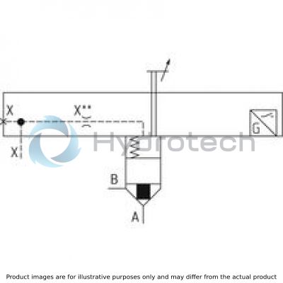
2-way cartridge valves are elements that have been designed for a compact block design. The power section with connections A and B is installed into the control block in a receiving hole standardized according to ISO 7368 and closed with a cover. In most cases, the cover is also the connection from the control side of the power section to the pilot control valves.
By control with respective pilot control valves, the power section can be applied for pressure, directional and throttle functions or a combination of these functions. Particularly efficient solutions are realized by adjustment of the size to various flows of the individual ways of an actuator. The application of power sections of elements for multiple functions is very cost-effective.
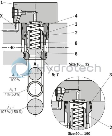
2-way cartridge valves generally consist of control cover (1) and installation kit (2). The control cover contains the control bores and optionally a stroke limitation function, a hydraulically controlled directional seat valve or a shuttle valve according to the required overall function. Additionally, electrically operated directional spool or seat valves can be installed at a control cover. The installation kit consists of a bushing (3), ring (4) (only up to NG32), valve poppet (5), optionally with damping nose (6) or without damping nose (7) as well as closing spring (8).
The function of 2-way cartridge valves is pressure-dependent. This way, three crucial pressurized areas A1, A2, A3 are realized for the function. The area at valve seat A1 is observed as 100 %. Depending on the version, the annulus area A2 realized by grading is 7 % or 50 % of area A1. The area ratio A1 : A2 is respectively either 14.3 : 1 or 2 : 1. The area A3 is identical to the sum of areas A1 + A2. Due to the different area ratios A1 : A2 and the resulting different annulus areas (A2), the area A3 is one time 107 % and another time 150 % of the area A1 at the seat, which is observed as 100 %.
In general, the following applies:
The areas A1 and A2 are effective in opening direction. The area A3 and the spring are effective in closing direction. The direction of action of the resulting force from the opening and closing forces determines the spool position of the 2-way cartridge valve.
The 2-way cartridge valves can be passed from A to B or from B to A. Pressurization of area A3 by pilot oil discharge from channel B or external pilot oil supply, channel A is blocked without leakage.
|
01 |
02 |
03 |
04 |
05 |
06 |
07 |
08 |
09 |
10 |
11 |
12 |
||
|
LFA |
EH2 |
– |
/ |
D |
Q..24 |
F |
|
Type |
|||
|
01 |
Control cover LFA |
LFA |
|
|
Size |
|||
|
02 |
NG 16 |
16 |
|
|
NG 25 |
25 |
||
|
NG 32 |
32 |
||
|
NG 40 |
40 |
||
|
NG 50 |
50 |
||
|
NG 63 |
63 |
||
|
NG 80 |
80 |
||
|
NG 100 |
100 |
||
|
NG 125 |
125 |
||
|
NG 160 |
160 |
||
|
Version |
|||
|
03 |
Control cover version "EH2" |
With electrical control of the closed position and stroke limitation incl. installation kit |
EH2 |
|
Component series |
|||
|
04 |
Component series 70 ... 79 (70 ... 79: unchanged installation and connection dimensions) 1) |
7X |
|
|
Component series 60 … 69 (60 … 69: unchanged installation and connection dimensions) 2) |
6X |
||
|
Component series 20 ... 29 (20 ... 29: unchanged installation and connection dimensions) 3) |
2X |
||
|
Spool design |
|||
|
05 |
A1 : A2 = 2 : 1 (annulus area = 50 %; standard version) |
CA |
|
|
A1 : A2 = 14.3 : 1 (annulus area = 7 %) |
CB |
||
|
Cracking pressure |
|||
|
06 |
Cracking pressure 1.0 bar |
10 |
|
|
Cracking pressure 2.0 bar |
20 |
||
|
Cracking pressure 4.0 bar |
40 |
||
|
Damping |
|||
|
07 |
Valve poppet with damping nose |
D |
|
|
Spool position monitoring |
|||
|
08 |
Electrical (NG 16…32) |
QMG24 |
|
|
Electrical (NG 40...160) |
Q6G24 |
||
|
Remote control port |
|||
|
09 |
With remote control port |
F |
|
|
Nozzle fitting |
|||
|
10 |
Orifice in channel X 4) |
X... |
|
|
Seal material |
|||
|
11 |
NBR seals |
no code |
|
|
FKM seals |
V |
||
|
Ports, plug screws and orifices |
|||
|
12 |
Metric |
no code |
|
|
UNC |
/12 |
||
| 1) Component series 7X for sizes 16…63. | |
| 2) Component series 6X for sizes 80 and 100. | |
| 3) Component series 2X for sizes 125 and 160. | |
| 4) This orifice is designed as screw-type orifice. If an orifice is to be installed, the respective code letter with the orifice Ø in 1/10 mm has to be entered in the type designation. | |
| Example: X12 = Orifice with Ø1.2 mm in channel X. |
|
Version |
|
|
„CA“ |
„CB“ |
 |
 |
|
Orifice symbol |
Symbol in ordering code |
|||
|
A** |
 |
A** |
This orifice is designed as screw-type orifice. If an orifice is to be installed, the respective code letter with the orifice Ø in 1/10 mm has to be entered in the type designation. Example: A12 = Orifice with Ø1.2 mm in channel A. |
|
|
Ø1,2 |
|
This orifice is designed as bore. No specifications are made in the type designation. (Orifice Ø in mm) |
||
|
Z12 |
 |
This orifice is designed as screw-type orifice. This is a standard orifice. No specifications are made in the type designation. (Orifice Ø in 1/10 mm) |
||
general
|
Size |
16 | 25 | 32 | 40 | 50 | 63 | 80 | 100 | 125 | 160 | ||
|
Ambient temperature range |
NBR seals |
°C |
-30 … +60 | |||||||||
|
FKM seals |
°C |
-20 … +60 | ||||||||||
|
MTTFD values according to EN ISO 13849 1) |
Years |
150 | ||||||||||
| 1) | For further details, see data sheet 08012 |
hydraulic
|
Size |
16 | 25 | 32 | 40 | 50 | 63 | 80 | 100 | 125 | 160 | ||
|
Maximum operating pressure |
Without directional valve |
bar |
400 | 420 | ||||||||
|
Anschluss A 1) |
bar |
315 350 |
||||||||||
|
Port B 1) |
bar |
315 350 |
||||||||||
|
Port X 1) |
bar |
315 350 |
||||||||||
|
With electrically monitored spool position |
bar |
400 | 420 | |||||||||
|
Maximum flow 2) |
l/min |
25000 | ||||||||||
|
Hydraulic fluid |
see table | |||||||||||
|
Hydraulic fluid temperature range |
NBR seals |
°C |
-30 … +80 | |||||||||
|
FKM seals |
°C |
-20 … +80 | ||||||||||
|
Viscosity range |
mm²/s |
2.8 … 500 | ||||||||||
|
Maximum admissible degree of contamination of the hydraulic fluid 3) |
Class 20/18/15 according to ISO 4406 (c) | |||||||||||
| 1) | dependent on the attached directional valve |
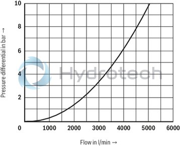
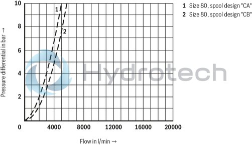
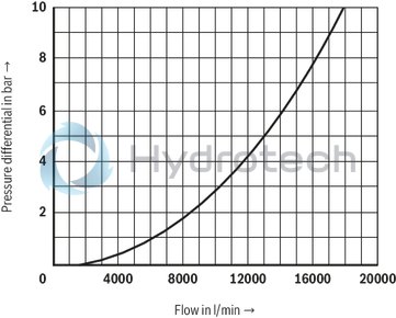
| 2) | NG-dependent; see characteristic curves |
| 3) | The cleanliness classes specified for the components must be adhered to in hydraulic systems. Effective filtration prevents faults and simultaneously increases the life cycle of the components. For the selection of the filters, see www.boschrexroth.com/filter. |
|
Hydraulic fluid |
Classification |
Suitable sealing materials |
Standards |
|
|
Mineral oils |
HL, HLP, HLPD, HVLP, HVLPD |
NBR, FKM |
DIN 51524 |
|
|
Bio-degradable |
Insoluble in water |
HETG |
NBR, FKM |
ISO 15380 |
|
HEES |
FKM |
|||
|
Soluble in water |
HEPG |
FKM |
ISO 15380 |
|
|
Containing water |
Water-free |
HFDU, HFDR |
FKM |
ISO 12922 |
|
Containing water |
HFC (Fuchs Hydrotherm 46M, Petrofer Ultra Safe 620) |
NBR |
ISO 12922 |
|
|
Important information on hydraulic fluids! For further information and data on the use of other hydraulic fluids, please refer to data sheet 90220 or contact us! There may be limitations regarding the technical valve data (temperature, pressure range, life cycle, maintenance intervals, etc.)! The flash point of the hydraulic fluid used must be 40 K higher than the maximum solenoid surface temperature.Flame-resistant – containing water: Maximum pressure differential at the seat 50 bar Pressure pre-loading at the tank port >20 % of the pressure differential; otherwise, increased cavitation Life cycle compared to operation with mineral oil HL, HLP 50 to 100 %
|
||||
|
Size of the annulus area |
|||||||||||
|
Surface in cm2 |
Version |
Size |
|||||||||
|
16 |
25 |
32 |
40 |
50 |
63 |
80 |
100 |
125 |
160 |
||
|
A1 |
„CA“ |
1,89 |
4,26 |
6,79 |
11,1 |
19,63 |
30,2 |
37,9 |
63,6 |
95 |
160,6 |
|
„CB“ |
2,66 |
5,73 |
9,51 |
15,55 |
26,42 |
41,28 |
52,8 |
89,1 |
133,7 |
224,8 |
|
|
A2 |
„CA“ |
0,95 |
1,89 |
3,39 |
5,52 |
8,64 |
14,0 |
18,84 |
31,4 |
48 |
79,9 |
|
„CB“ |
0,18 |
0,43 |
0,67 |
1,07 |
1,85 |
2,90 |
3,94 |
5,9 |
9,3 |
15,7 |
|
|
Spool form (damping nose) |
|||||||||||
|
Size |
|||||||||||
|
16 |
25 |
32 |
40 |
50 |
63 |
80 |
100 |
125 |
160 |
||
|
Stroke |
cm |
0,9 |
1,17 |
1,4 |
1,9 |
2,3 |
2,8 |
3,0 |
3,8 |
4,8 |
6,5 |
|
Pilot volume |
cm3 |
2,56 |
7,21 |
14,3 |
31,6 |
65,0 |
124 |
170 |
361 |
687 |
1563 |
|
Theoretical pilot flow 1) |
l/min |
15,4 |
43,3 |
86 |
190 |
390 |
744 |
1020 |
2166 |
4122 |
9378 |
|
Cracking pressure in bar |
|||||||||||
|
Version |
Size |
||||||||||
|
16 |
25 |
32 |
40 |
50 |
63 |
80 |
100 |
125 |
160 |
||
|
Direction of flow A to B |
„CA10“ |
0,70 |
0,68 |
0,72 |
0,71 |
0,67 |
0,64 |
0,88 |
0,88 |
0,88 |
‒ |
|
„CA20“ |
2,03 |
2,18 |
2,12 |
2,02 |
2,01 |
2,0 |
1,75 |
1,75 |
1,76 |
1,94 |
|
|
„CA40“ |
3,50 |
3,90 |
3,80 |
4,0 |
4,11 |
3,8 |
3,13 |
3,04 |
‒ |
‒ |
|
|
„CB10“ |
0,49 |
0,50 |
0,51 |
0,51 |
0,48 |
0,47 |
0,63 |
0,63 |
0,62 |
‒ |
|
|
„CB20“ |
1,44 |
1,62 |
1,52 |
1,44 |
1,5 |
1,5 |
1,26 |
1,25 |
1,25 |
1,4 |
|
|
„CB40“ |
2,48 |
2,90 |
2,70 |
2,86 |
3,05 |
2,8 |
2,25 |
2,17 |
‒ |
‒ |
|
|
Direction of flow B to A |
„CA10“ |
1,38 |
1,53 |
1,42 |
1,43 |
1,47 |
1,37 |
1,77 |
1,78 |
1,73 |
‒ |
|
„CA20“ |
4,05 |
4,91 |
4,25 |
4,06 |
4,57 |
4,33 |
3,53 |
3,54 |
3,50 |
3,9 |
|
|
„CA40“ |
6,96 |
8,74 |
7,6 |
8,05 |
9,34 |
8,15 |
6,3 |
6,2 |
‒ |
‒ |
|
|
„CB10“ |
7,43 |
6,69 |
7,24 |
7,37 |
6,88 |
6,62 |
8,4 |
9,4 |
8,9 |
‒ |
|
|
„CB20“ |
21,3 |
21,5 |
21,6 |
20,9 |
21,4 |
20,9 |
16,9 |
18,7 |
17,9 |
20 |
|
|
„CB40“ |
36,6 |
38,3 |
38,6 |
41,5 |
43,6 |
39,4 |
30,2 |
32,5 |
‒ |
‒ |
|
| 1) Switching time = 10 ms |
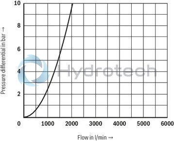
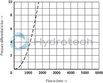
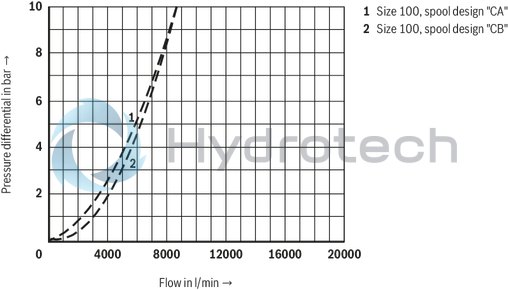
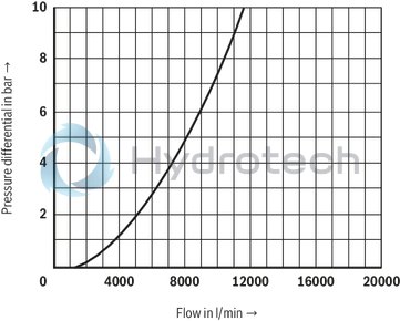
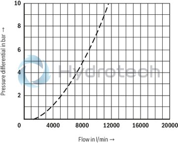
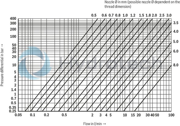
For applications outside these parameters, please consult us!
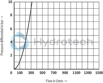
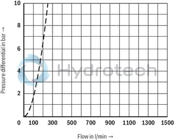
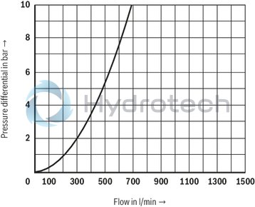
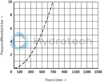
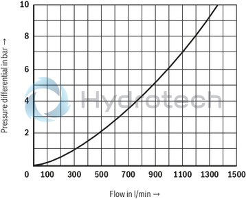
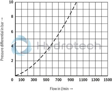
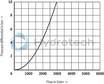
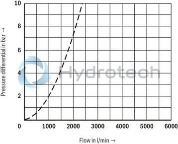
(simulated with HLP46, ϑoil = 40±5 °C)
Size 16 (A → B)
Size 16 (B → A)
Size 25 (A → B)
Size 25 (B → A)
Size 32 (A → B)
Size 32 (B → A)
Size 40 (A → B)
Size 40 (B → A)
Size 50 (A → B)
Size 50 (B → A)
Size 63 (A → B)
Size 63 (B → A)
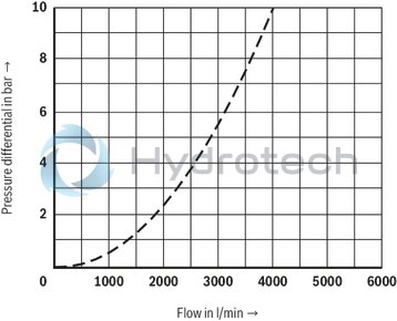
Size 80 (A → B)
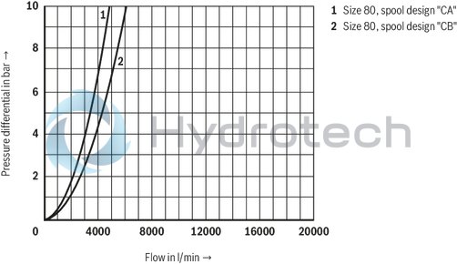
Size 80 (B → A)
Size 100 (A → B)
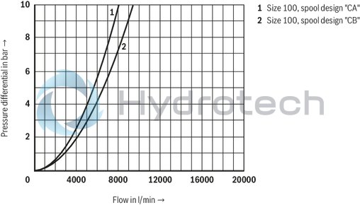
Size 100 (B → A)
Size 125 (A → B)
Size 125 (B → A)
Size 160 (A → B)
Size 160 (B → A)
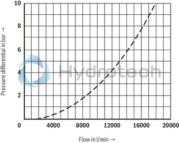
Notice:
The indicated characteristic curves have been determined without inserted springs.
|
Orifices |
|
|
Thread |
Orifice Ø in mm |
|
M6 conical |
0,5 … 3,0 |
|
M8 x 1 conical |
0,5 … 4,0 |
|
G3/8 |
0,8 … 6,0 |
|
G1/2 |
1,0 … 8,0 |
Other orifices upon request.
|
Plug screws |
|
|
Thread |
Tightening torqueMA in Nm |
|
M6 |
– |
|
M8 x 1 |
7 |
|
G3/8 |
55 |
|
G1/2 |
80 |
|
G3/4 |
135 |
|
G1 |
225 |
|
G1 1/4 |
360 |
LFA . EH2… (NG16 … 32)
LFA . EH2… (NG40 … 160)
Inductive position switch type QM
The electrical connection is realized via a 4-pole mating connector (separate order) with connection thread M12 x 1.
electrical
|
Connection voltage (DC voltage) |
Connection voltage (DC voltage) |
V |
24 |
| +30 %/-15 % | |||
|
Admissible residual ripple |
% |
≤ 10 | |
|
Max. load capacity |
mA |
400 | |
|
Switching outputs 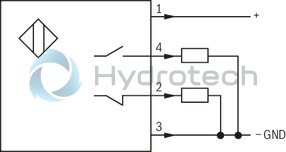 |
PNP transistor outputs, load between switching outputs and GND | ||
|
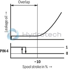
Pinout  |
1 |
+24 V | |
|
2 |
Switching output: 400 mA | ||
|
3 |
0 V, GND | ||
|
4 |
Switching output: 400 mA | ||
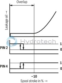
Switching logics
Inductive position switch type Q6
|
Connection voltage (DC voltage) |
Connection voltage (DC voltage) |
V |
24 |
| +30 %/-15 % | |||
|
Admissible residual ripple |
% |
≤ 10 | |
|
Max. load capacity |
mA |
200 | |
|
Switching outputs 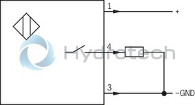 |
PNP transistor outputs, load between switching outputs and GND | ||
|
Pinout |
1 |
+24 V | |
|
2 |
free | ||
|
3 |
0 V, GND | ||
|
4 |
Switching output: 200 mA | ||
Switching logics
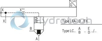
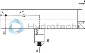
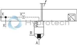
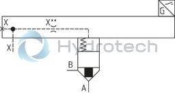
Cartridge element (design as seat valve with damping noses)
Cartridge valves are hydraulically controlled seat or spool valves with two working ports A and B and one control port X or two control ports X and Z for the version with differential spool. Y is generally the leakage oil connection. The valves are available in sizes 16, 25, 32, 40, 50, 63, 80, 100, 125 and 160.
Criteria for determination of the size include the flow to be controlled as well as flow resistance values of cartridge valves and their area ratios.
Control cover
By means of control cover (2), the bore of the cartridge elements is closed. They also serve as connection element between cartridge valve and pilot control valve.
Pilot control valve
At control covers for set-up of a directional spool valve (3) or seat valve (4), the porting pattern is realized according to ISO 4401 and DIN 24340.
The cartridge element (1) and the control cover (2) form a functional unit. It is calibrated at the factory and must not be disassembled or combined with other third-party components.
The closed spool position is monitored by the attached position switch (5).
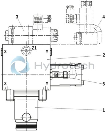
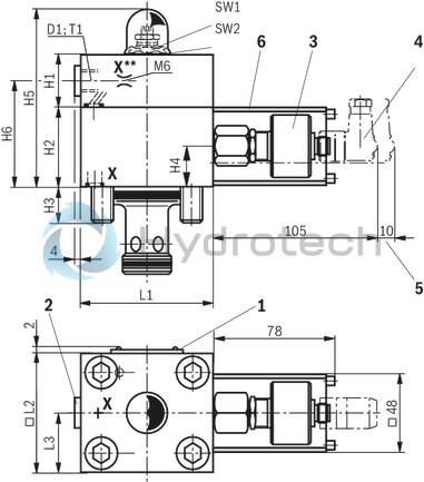
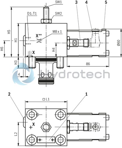
Control cover "EH2" with electrical control of the closed position and stroke limitation incl. installation kit NG16 … 32
Dimensions in mm
|
1 |
Name plate |
|
2 |
Port X as threaded port |
|
3 |
Position switch type Q6 (QM at NG40) |
|
4 |
Angled mating connector (separate order, material no. R900082899) |
|
5 |
Protective housing |
|
1 |
Name plate |
|
2 |
Port X as threaded port |
|
3 |
Position switch type QM |
|
4 |
Angled mating connector (separate order, material no. R900082899) |
|
5 |
Space required to remove the mating connector |
|
6 |
Protective housing |
Notice:
The tightening torques stated are guidelines when using screws with the specified friction coefficients and when using a manual torque wrench (tolerance ± 10 %). The specified tightening torques were calculated with total friction coefficient μ = 0.14; adjust in case of modified surfaces.Notice:
The dimensions are nominal dimensions which are subject to tolerances.
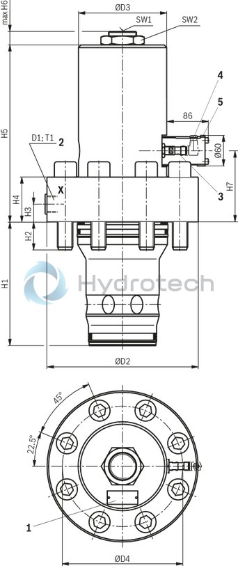
Control cover "EH2" with electrical control of the closed position and stroke limitation incl. installation kit NG40 … 63
Dimensions in mm
|
1 |
Name plate |
|
2 |
Port X as threaded port |
|
3 |
Position switch type Q6 (QM at NG40) |
|
4 |
Angled mating connector (separate order, material no. R900082899) |
|
5 |
Protective housing |
|
1 |
Name plate |
|
2 |
Port X as threaded port |
|
3 |
Position switch type QM |
|
4 |
Angled mating connector (separate order, material no. R900082899) |
|
5 |
Space required to remove the mating connector |
|
6 |
Protective housing |
Notice:
The tightening torques stated are guidelines when using screws with the specified friction coefficients and when using a manual torque wrench (tolerance ± 10 %). The specified tightening torques were calculated with total friction coefficient μ = 0.14; adjust in case of modified surfaces.Notice:
The dimensions are nominal dimensions which are subject to tolerances.
Control cover "EH2" with electrical control of the closed position and stroke limitation incl. installation kit NG80 … 100
Dimensions in mm
|
1 |
Name plate |
|
2 |
Port X as threaded port |
|
3 |
Position switch type Q6 |
|
4 |
Angled mating connector (separate order, material no. R900082899) |
|
5 |
Protective housing |
Notice:
The tightening torques stated are guidelines when using screws with the specified friction coefficients and when using a manual torque wrench (tolerance ± 10 %). The specified tightening torques were calculated with total friction coefficient μ = 0.14; adjust in case of modified surfaces.Notice:
The dimensions are nominal dimensions which are subject to tolerances.
Control cover "EH2" with electrical control of the closed position and stroke limitation incl. installation kit NG125 … 160
Dimensions in mm
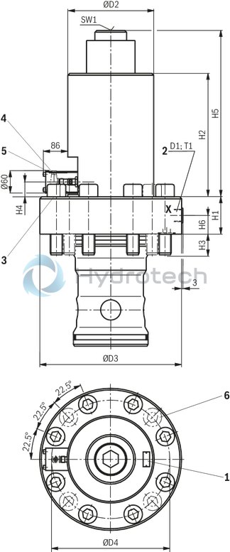
|
1 |
Name plate |
|
2 |
Port X as threaded port |
|
3 |
Position switch type Q6 |
|
4 |
Angled mating connector (separate order, material no. R900082899) |
|
5 |
Protective housing |
|
6 |
4 additional valve mounting screws at NG160 |
Notice:
The tightening torques stated are guidelines when using screws with the specified friction coefficients and when using a manual torque wrench (tolerance ± 10 %). The specified tightening torques were calculated with total friction coefficient μ = 0.14; adjust in case of modified surfaces.Notice:
The dimensions are nominal dimensions which are subject to tolerances.
|
Hexagon socket head cap screws ISO 4762 - 10.9 |
||
|
Size |
Quantity |
Tightening torqueMA in Nm |
|
16 |
4 |
32 |
|
25 |
4 |
110 |
|
32 |
4 |
270 |
|
40 |
4 |
520 |
|
50 |
4 |
520 |
|
63 |
4 |
1800 |
|
80 |
8 |
900 |
|
100 |
8 |
1800 |
|
125 |
8 |
3100 |
|
160 |
12 |
5000 |
Notice:
The tightening torques stated are guidelines when using screws with the specified friction coefficients and when using a manual torque wrench (tolerance ± 10 %). The specified tightening torques were calculated with total friction coefficient μ = 0.14; adjust in case of modified surfaces.Notice:
The dimensions are nominal dimensions which are subject to tolerances.
|
NG |
D1 |
H1 |
H2 |
H3 |
H4 |
H5 |
H6 |
L1 |
▢ L2 |
L3 |
T1 |
SW1 |
SW2 |
|
mm |
mm |
mm |
mm |
mm |
mm |
mm |
mm |
mm |
mm |
mm |
mm |
||
| 16 | G 1/8 | 35 | 50 | 15 | 25 | 126 | 62 | 65 | 80 | 32.5 | 8 | 6 | 21 |
| 25 | G1/4 | 40 | 50 | 24 | 25 | 130 | 66 | 85 | 85 | 42.5 | 12 | 6 | 21 |
| 32 | G1/4 | 50 | 50 | 28 | 25 | 150 1) | 66 | 100 | 100 | 50 | 12 | 10 | 27 |
| 1) | Maximum dimension |
|
NG |
D1 |
H1 |
H3 |
H4 |
H5 1) |
H6 |
▢ L1 |
L2 |
T1 |
SW1 |
SW2 |
|
mm |
mm |
mm |
mm |
mm |
mm |
mm |
mm |
mm |
mm |
||
| 40 | G1/2 | 190 | 32 | 25 | 233 | 84.5 | 125 | 62.5 | 14 | 14 | 46 |
| 50 | G1/2 | 210 | 34 | 59 | 255 | 95 | 140 | 70 | 14 | 17 | 55 |
| 63 | G3/4 | 246 | 50 | 72.5 | 295 | 120 | 180 | 90 | 16 | 24 | 65 |
| 1) | Maximum dimension |
|
NG |
D1 |
ØD2 |
ØD3 |
ØD4 |
H1 |
H2 |
H3 |
H4 |
H5 |
H6 |
H7 |
T1 |
SW1 |
SW2 |
|
mm |
mm |
mm |
mm |
mm |
mm |
mm |
mm |
mm |
mm |
mm |
mm |
mm |
||
| 80 | G3/4 | 250 | 150 | 200 | 205 | 45 | 40 | 76.5 | 305 | 58 | 105 | 16 | 75 | 24 |
| 100 | G1 | 300 | 175 | 245 | 245 | 52.5 | 35 | 88.5 | 350 | 68 | 140.5 | 18 | 75 | 27 |
|
NG |
D1 |
ØD2 |
ØD3 |
ØD4 |
H1 |
H2 |
H3 |
H4 |
H5 |
H6 |
T1 |
SW1 |
|
mm |
mm |
mm |
mm |
mm |
mm |
mm |
mm |
mm |
mm |
mm |
||
| 125 | G1 | 230 | 380 | 300 | 100 | 330 | 61 | 40 | 445 | 50 | 18 | 32 |
| 160 | G1 | 300 | 480 | 400 | 167 | 383 | 74 | 38 | 498 | 70 | 18 | 32 |
Inductive position switches
Contactless position switches with integrated switching amplifiers are switched shortly before reaching the spool position to be monitored. The spool position reached is displayed by a binary signal.
Advantages of the position switches:
Short-circuit-proof Direct monitoring of the spool position at the control spool. Long life cycle High reliability due to no use of dynamic seals Reaction time of the switch upon operation approx. 15 ms.Notice:
Valves with inductive position switches and proximity sensors in safety-relevant controls may only be assembled and commissioned by hydraulically and electrically trained specialists. Service work requires special tools and equipment. This work may only be performed by authorized specialists or in the factory!
Improper work at safety equipment leads to a risk of personal injury and damage to property!
The valve components are coordinated in the production plant and adjusted during assembly. They must not be interchanged. In case of valve or position switch defects, the complete valve must be exchanged! The factory setting of the position switch must not be changed. The position switch may only be set by Bosch Rexroth. The position switch must be automatically monitored by the machine control to prevent initiation of a new machine cycle even in case of a defect at the position switch.Orifice selection
Mating connectors for sensors and valves with connector “K24”, “K35” and “K72”, M12 x 1
4P Z24
Mating connectors for sensors and valves with connector “K24”, “K35” and “K72”, M12 x 1
4P Z24
For sensors and valves with connector “K24”, “K35” and “K72” Mating connectors M12, 4-pole, line cross-section 0.75 mm2Data sheet
Spare parts & repair