
BOSCH REXROTH
DBW52BP2-3X/315U6EW110N9DALV
R901158855
Pressure Relief Valves
Pressure valves: DB* 52.-3x/
BOSCH REXROTH
MATERIAL: R901158855
SUMMARY: Pressure valves: DB* 52.-3x/
Quantity in stock: 0
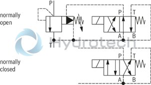
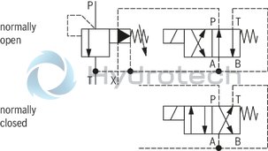
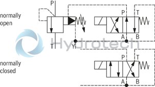
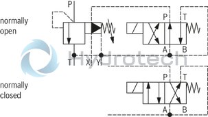
Pressure valve type DBW is a pilot-operated pressure relief valve. It is used for limiting (DBW) a system pressure.
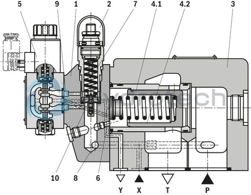
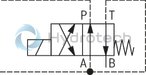
The pressure relief valves basically consist of the pilot control valve (1) with pressure adjustment element (2), main valve (3) with main spool insert (4) and directional valve (5), optional.
Pressure relief valves type DBW
In principle, the function of this valve is the same as that of valve type DBW. The unloading of the main spool (4) is, however, achieved by controlling the mounted directional valve (5).
To reduce the tank pressure peaks when switching to depressurized circulation by operating the directional valve, the main spool in sliding spool design (4.1) can be used.
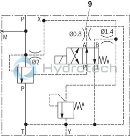
Influencing of the switch-off time
The nozzle (9), by default equipped with Ø0.8 mm, is used to influence the switch-off time. By exchanging this nozzle (9), the switch-off time can be set to a slower or faster value.
The pressure limiting function is thus not influenced.
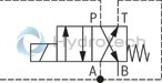
Principle:
Type DBW 52 BP2.3X/…XYU6EG24N9K4
With type DBW 52 …Y…, the connection T–Y is closed.
|
4.1 |
Sliding spool |
|
4.2 |
Seat control spool |
|
01 |
02 |
03 |
04 |
05 |
06 |
07 |
08 |
09 |
10 |
11 |
12 |
13 |
14 |
15 |
16 |
17 |
18 |
|
|
DB |
52 |
3X |
/ |
U |
* |
|
01 |
Pressure relief valve |
DB |
|
|
02 |
with attached directional valve |
W |
|
|
03 |
Size 52 |
52 |
|
|
04 |
 |
Normally closed |
A1) |
 |
Normally open |
B1) |
|
|
Version |
|||
|
05 |
For subplate mounting |
P |
|
|
for flange connection |
F |
||
|
Adjustment type for pressure adjustment |
|||
|
06 |
Rotary knob |
1 |
|
|
Sleeve with hexagon and protective cap |
2 |
||
|
Lockable rotary knob |
32) |
||
|
Main piston |
|||
|
07 |
in seat spool design |
– |
|
|
in sliding spool design |
L |
||
|
08 |
Component series 30 ... 39 (30 ... 39: unchanged installation and connection dimensions) |
3X |
|
|
Pressure rating |
|||
|
09 |
Set pressure up to 100 bar |
100 |
|
|
Set pressure up to 315 bar |
315 |
||
|
Pilot oil supply |
|||
|
10 |
Ordering code according to symbols |
– |
|
|
X |
|||
|
Y |
|||
|
XY |
|||
|
11 |
for minimum cracking pressure 3 bar |
U |
|
|
12 |
with directional valve NG6 |
6E1) |
|
|
13 |
Direct voltage 24 V |
G241) |
|
|
Alternating voltage 230 V, 50/60 Hz |
W2301) |
||
|
14 |
With concealed manual override |
N91) |
|
|
With manual override |
N1) |
||
|
Electrical connection Individual connection |
|||
|
15 |
without mating connector with connector DIN EN 175301-803 |
K43) |
|
|
Seal material |
|||
|
16 |
NBR seals |
no code |
|
|
FKM seals (other seals upon request) |
V |
||
|
Observe compatibility of seals with hydraulic fluid used. |
|||
|
Type-examination procedure |
|||
|
17 |
Without type-examination procedure |
no code |
|
|
Type-examination tested safety valve according to PED 2014/68/EU |
E |
||
|
18 |
Further details in the plain text |
* |
|
| 1) Ordering code only necessary with versions with mounted directional valve (DBW). | |
| 2) H-key with the order no. R900008158 is included in the scope of delivery | |
| 3) Mating connectors, separate order |
Preferred types and standard units are contained in the EPS (standard price list).
Minimum stability of the materials for subplates, flanges, etc.:
The materials are to be selected so that there is sufficient safety for all imaginable operating conditions, e.g. for pressure resistance, thread stripping strength and tightening torques.
hydraulic
|
Version |
Pilot oil flow "no code" | Pilot oil flow "Y" | ||
|
Maximum counter pressure |
Port Y |
bar |
- | 0 |
|
Port T |
See characteristic curves and explanatory notes for maximum counter pressure | PT < 15 | ||
|
Maximum flow |
See ordering code, safety instructions and characteristic curves "Type-examination tested safety valve" | |||
|
Hydraulic fluid |
Mineral oil (HL, HLP) according to DIN 51524 and DIN 51524-1 | |||
|
Viscosity range |
mm²/s |
12 … 230 | ||
|
Hydraulic fluid |
Classification |
Suitable sealing materials |
Standards |
|
|
Mineral oil |
HL, HLP |
FKM, NBR |
DIN 51524 |
|
|
Bio-degradable |
Insoluble in water |
HEES (synthetic esters) |
FKM |
VDMA 24568 |
|
HETG (rape seed oil) |
FKM, NBR |
|||
|
Soluble in water |
HEPG (polyglycols) |
FKM |
VDMA 24568 |
|
|
Other hydraulic fluids on request |
||||
Deviating technical data for type-examination tested safety valves 1)
hydraulic
|
Size |
52 | ||
|
Maximum operating pressure |
Port P |
bar |
315 |
|
Port X |
bar |
315 | |
|
Port T |
bar |
315 | |
|
Maximum counter pressure |
Port Y (DC solenoid) 1) |
bar |
210 |
|
Port T (AC solenoid) 2) |
bar |
160 | |
|
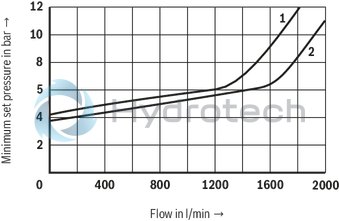
Minimum set pressure |
flow-dependent, see characteristic curves | ||
|
Maximum set pressure |
bar |
100 315 |
|
|
Maximum flow |
l/min |
2000 | |
|
Hydraulic fluid |
see table | ||
|
Hydraulic fluid temperature range |
NBR seals |
°C |
-30 … +80 |
|
FKM seals |
°C |
-15 … +80 | |
|
Viscosity range |
mm²/s |
10 … 380 | |
|
Maximum admissible degree of contamination of the hydraulic fluid 3) |
Class 20/18/15 according to ISO 4406 (c) | ||
| 1) | DC solenoid |
| 2) | AC solenoid |
| 3) | The cleanliness classes specified for the components must be adhered to in hydraulic systems. Effective filtration prevents faults and simultaneously increases the life cycle of the components. For the selection of the filters, see www.boschrexroth.com/filter. |
general
|
Size |
52 | ||
|
Weight (approx.) |
kg |
28.5 | |
|
Installation position |
any | ||
|
Ambient temperature range |
NBR seals |
°C |
-30 … +50 |
|
FKM seals |
°C |
-15 … +50 | |
For applications outside these parameters, please consult us!
(measured with HLP46, ϑOil = 40 ±5 °C)
Die characteristic curve were measured with external pilot oil return and depressurized pilot oil return flow.
Due to the internal pilot oil return, the inlet pressure increases by the output pressure present in port T.
|
1 |
Main spool insert with sliding spool |
|
2 |
Main spool insert with seat spool |
|
pA |
Response pressure in bar |
|
pT |
max. admissible counter pressure in the discharge line (port T) (sum of all possible counter pressures; also see AD2000 data sheet - A2) |
|
10 % x pA (with qV = 0 l/min) |
|
|
maximum admissible flow in l/min |
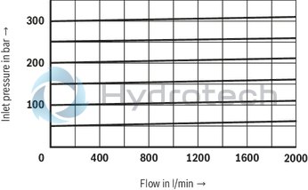
Maximum admissible flow qVmax dependent on the counter pressure pT in the discharge line with internal pilot oil return
Type DBW 52 ..3X/...E
Characteristic curves for intermediate values can be generated by interpolation.
|
1 |
Main spool insert with sliding spool |
|
2 |
Main spool insert with seat spool |
|
pA |
Response pressure in bar |
|
pT |
max. admissible counter pressure in the discharge line (port T) (sum of all possible counter pressures; also see AD2000 data sheet - A2) |
|
10 % x pA (with qV = 0 l/min) |
|
|
maximum admissible flow in l/min |
|
Explanation of the diagram |
||
|
Example: |
||
|
known: |
system/accumulator flow to be secured |
qVmax = 500 l/min |
|
set response pressure of the safety valve |
pA = 210 bar |
|
|
unknown: |
pT = ? |
|
|
Solution: |
see arrows in diagram: |
pT(500 l/min; 210 bar) = 10 bar |
Type DBW 52 …–..
Type DBW 52 …X..
Type DBW 52 …Y..
Type DBW 52 …XY..
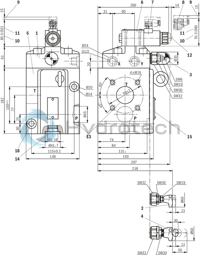
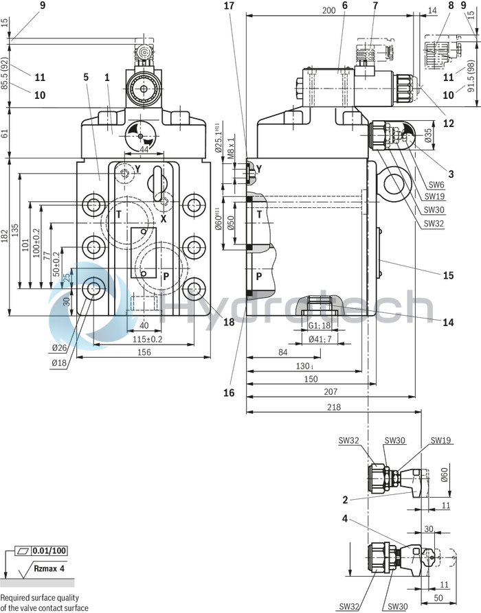
Flange connection
Dimensions in mm
|
1 |
Pilot control valve |
|
2 |
Adjustment type "1" |
|
3 |
Adjustment type "2" |
|
4 |
Adjustment type "3" |
|
5 |
Main valve |
|
6 |
Directional seat valve NG6 |
|
7 |
Mating connector without circuitry (separate order) |
|
8 |
Mating connector with circuitry (separate order) |
|
9 |
Space required to remove the mating connector |
|
10 |
Dimension for valve with DC solenoid |
|
11 |
Dimension ( ) for valve with AC solenoid |
|
12 |
Optional auxiliary operating device |
|
13 |
Connection flanges (T and P) |
|
14 |
Pressure gauge connection |
|
15 |
Name plate |
|
18 |
Valve mounting bores |
Attention!
Please use the existing mounting bores to fix the valve so that the reaction forces can be absorbed in a risk-free manner!
Subplate mounting
Dimensions in mm
|
1 |
Pilot control valve |
|
2 |
Adjustment type "1" |
|
3 |
Adjustment type "2" |
|
4 |
Adjustment type "3" |
|
5 |
Main valve |
|
6 |
Directional seat valve NG6 |
|
7 |
Mating connector without circuitry (separate order) |
|
8 |
Mating connector with circuitry (separate order) |
|
9 |
Space required to remove the mating connector |
|
10 |
Dimension for valve with DC solenoid |
|
11 |
Dimension ( ) for valve with AC solenoid |
|
12 |
Optional auxiliary operating device |
|
14 |
Pressure gauge connection |
|
15 |
Name plate |
|
16 |
Identical seal rings for ports P and T |
|
17 |
Identical seal rings for ports X and Y |
|
18 |
Valve mounting bores |
Valve mounting screws for flange connection (separate order)
2 hexagon socket head cap screws ISO 4762 - M12 - 10.9Valve mounting screws for subplate mounting (separate order)
6 hexagon socket head cap screws ISO 4762 - M16 x 150 - 10.9-flZn-240h-L(friction coefficient μtotal = 0.09 to 0.14);
tightening torque MA = 229 Nm ± 10 %,
material no. R913000154
Subplate for subplate mounting (separate order):
G 479/10

Safety instructions: Type-examination tested safety valves (type DBW 52 ...E) according to Pressure Equipment Directive 97/23/EC
The unloading function (directional valve function with DBW) must not be used for safety functions! With type DBW 52 B..3X/..., the lowest adjustable pressure (circulation pressure) is set in case of power failure or cable break. With type DBW 52 A..3X/..., the pressure limiting function is set in case of power failure or cable break. Hydraulic counter pressures in port T with internal pilot oil return and/or port Y with external pilot oil return add 1:1 to the response pressure of the valve set at the pilot control.Example:
Pressure adjustment of the valve due to spring pretensioning item 7 on page 4 in the pilot control valve/adjustment unit
pspring = 200 bar
Hydraulic counter pressure in port T with internal pilot oil return
phydraulic = 50 bar
=> Response pressure pspring + phydraulic = 250 bar
Before ordering a type-examination tested safety valve, it must be observed that for the desired response overpressure p, the maximum admissible flow qV max of the safety valve must be larger than the maximum possible flow of the system. In this respect, the applicable regulations must be observed! According to PED 97/23/EC, the increase in the system pressure due to the flow must not exceed 10% of the set response pressure (see component marking). Discharge lines (ports T and Y) of safety valves must end in a risk-free manner. The accumulation of fluids in the discharge lines must not be possible. If a lead seal at the safety valve is removed, the approval according to the PED! The requirements of the Pressure Equipment Directive 97/23/EC and of data sheet AD2000 A2 must be generally observed! Attention! Possible unloading via the directional valve must not be applied for safety-relevant functions! If unloading is required for safety-relevant functions, an additional safety valve must be installed.It is imperative to observe the application notes!
In the plant, the response pressure specified in the component marking is set at a flow of 12 l/min.
The maximum admissible flow stated in the component marking (= numerical value instead of the character "G" in the component marking, see ordering code, type-examination tested safety valves) must not be exceeded.
It applies to:
Pilot oil return “external” (= Y in the ordering key) without counter pressure in the discharge line Y, admissible counter pressure in the discharge line (port T) < 15 bar Pilot oil return “internal” (= no code in the ordering key). The maximum admissible flow is only admissible without counter pressure in the discharge line (port T).With internal pilot oil return, the system pressure increases by the counter pressure in the discharge line (port T) with increasing flow (observe AD2000 - data sheet A2 - item 6.3!).
To ensure that this increase in system pressure caused by the flow does not exceed the value of 10% of the set response pressure, the admissible flow has to be reduced dependent on the counter pressure in the discharge line (port T) (see diagram Safety instructions, Type-examination tested safety valves).
Mating connectors for valves with connector “K4”, without circuitry, standard
3P Z4
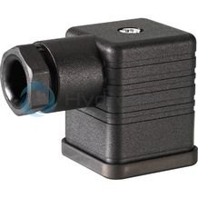
Mating connectors for valves with connector “K4”, without circuitry, standard
3P Z4
For valves with connector “K4” according to EN 175301-803 and ISO 4400, 2-pole + PE, “large cubic connector” Mating connectors for valves with one or two solenoids (individual connection)Data sheet
Spare parts & repair
Mating connectors for valves with connector “K4”, with indicator light
3P Z5L
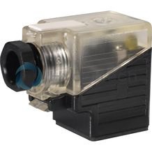
Mating connectors for valves with connector “K4”, with indicator light
3P Z5L
For valves with connector “K4” according to EN 175301-803 and ISO 4400, 2-pole + PE, “large cubic connector” Mating connectors for valves with one or two solenoids (individual connection)Data sheet
Spare parts & repair
Mating connectors for valves with connector “K4”, with indicator light and Zener diode suppression circuit
3P Z5L1
Mating connectors for valves with connector “K4”, with indicator light and Zener diode suppression circuit
3P Z5L1
For valves with connector “K4” according to EN 175301-803 and ISO 4400, 2-pole + PE, “large cubic connector” Mating connectors for valves with one or two solenoids (individual connection)Data sheet
Spare parts & repair
Mating connectors for valves with connector “K4”, with rectifier
3P RZ5
Mating connectors for valves with connector “K4”, with rectifier
3P RZ5
For valves with connector “K4” according to EN 175301-803 and ISO 4400, 2-pole + PE, “large cubic connector” Mating connectors for valves with one or two solenoids (individual connection)Data sheet
Spare parts & repair
Ordering code: Type-examination tested safety valves (type DBW 52 ...E) according to Pressure Equipment Directive 97/23/EC
|
Designation |
Component marking |
Maximum admissible flow qVmax in l/min with pilot oil return |
Set response overpressurep in bar |
|
|
external "Y" |
internal "–" |
|||
|
1 2 3 4 5 6 7 DBW 52 ▢▢▢▢3X/▢▢U6 ▢▢E |
TÜV.SV.▢ – 734.46.F.G.p |
1000 1500 2000 |
500 1000 1500 |
50 ... 110 111 ... 210 211 ... 315 |
|
1 ▢ |
Directional valve, normally closed |
A |
|
Directional valve, normally open |
B |
|
|
2 ▢ |
For subplate mounting |
P |
|
for flange connection |
F |
|
|
3 ▢ |
Adjustment element hand wheel (pressure adjustment sealed, unloading or setting of a lower response pressure possible) |
1 |
|
Adjustment element with sealed protective cap (no adjustment/unloading possible) |
2 |
|
|
4 ▢ |
Valve with seat main spool |
– |
|
Valve with sliding main spool |
L |
|
|
5 ▢ |
Pressure in the designation is to be entered by the customer, e.g. pressure adjustment ≥ [si]50 bar[/si][imp]725 psi[/imp] and possible in [si]5 bar[/si] [/imp]75 psi[/imp] steps. |
150 |
|
6 ▢ |
Pilot oil supply and return, internal |
– 1) 2) |
|
Recommendation Internal pilot oil supply, external pilot oil return |
Y 2) |
|
|
7 ▢ |
NBR seals |
no code |
|
FKM seals |
V |
|
|
▢ |
Value entered at the factory |
|
| 1) Dash “–” only necessary with version with attached directional valve | |
| 2) External pilot oil supply “X” not possible! |