
BOSCH REXROTH
HED5OH-3X/200K14
R901186322
Pressure Switches
Switch HED5.3X/
BOSCH REXROTH
MATERIAL: R901186322
SUMMARY: Switch HED5.3X/
Quantity in stock: 0
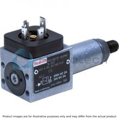
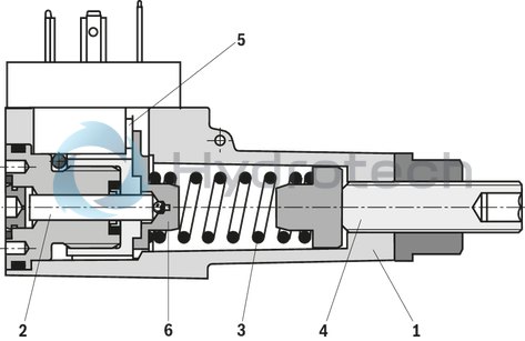
Hydro-electric pressure switches of type HED 5 are piston type pressure switches.
They basically consist of housing (1), installation kit with piston (2), compression spring (3), adjustment element (4) and micro switch (5)
The pressure to be monitored acts on the piston (2)
The latter is supported by the spring plate (6) and acts against the continuously adjustable force of the compression spring (3).
The spring plate (6) transmits the movement of the piston (2) onto the micro switch (5). This switches the electric circuit on or off, depending on the circuit set-up.
Notice:
In order to increase the life cycle, the pressure switch should be mounted with low vibrations and protected from hydraulic pressure surges.
|
01 |
Piston type pressure switch |
HED5 |
|
02 |
Flange connection |
OH |
|
03 |
Component series 30 ... 39 (version “G and “P”) (30 ... 39: unchanged installation and connection dimensions) |
3X |
|
04 |
Pressure rating maximum 50 bar |
50 |
|
Pressure rating maximum 100 bar |
100 |
|
|
Pressure rating maximum 200 bar |
200 |
|
|
Pressure rating maximum 350 bar |
350 |
|
|
Electrical connection |
||
|
05 |
Individual connection |
|
|
Without mating connector; connector DIN EN 175301-803 |
K14 1) |
|
|
Seal material |
||
|
07 |
NBR seals |
no code |
|
FKM seals |
V |
|
|
Low-temperature seals (max. 315 bar) |
MT |
|
|
Observe compatibility of seals with hydraulic fluid used. (Other seals upon request) |
||
|
08 |
Further details in the plain text |
|
| 1) Mating connectors, separate order, see accessories |
Type
|
Component series |
3X |
General
|
Weight |
m |
kg |
0.2 | |
|
Installation position |
any | |||
|
Ambient temperature ranges (NBR seals) |
ϑ |
°C |
-30 … +50 | |
|
Ambient temperature ranges (FKM seals) |
ϑ |
°C |
-20 … +50 | |
|
Ambient temperature range (low-temperature seal) |
ϑ |
°C |
-40 … +50 | |
|
Sine test |
DIN EN 60068-2-6:1996-05, 10...2000 Hz, max. 10 g, 10 double cycles | |||
|
Transport shock |
DIN EN 60068-2-27:1995-03, half-sine 15 g / 11 ms, 3 x in positive direction, 3 x in negative direction (a total of 6 single shocks per axis) | |||
|
Noise test |
DIN EN 60068-2-64: 1995-08, 20...2000 Hz, 14gRMS, 24 h | |||
|
Conformity/certification |
CE |
DIN EN 61058-1: 2002 / A2: 2008 DIN EN 60947-1: 2007 / A1: 2011 DIN EN 60947-5-1: 2004 / A1: 2009 DIN EN 60529: 1991 / A2: 2013 |
||
|
UL |
UL, 508 17th edition File No E223220 (up to 350 bar) | |||
|
CCC |
GB 14048.5-2008 | |||
Hydraulisch
|
Pressure rating |
p |
bar |
50 | 100 | 200 | 350 |
|
Operating pressure NBR/FKM seals, max. |
p |
bar |
350 | 400 | ||
|
Pressure adjustment range (decreasing) |
p |
bar |
5 … 50 | 10 … 100 | 15 … 200 | 25 … 350 |
|
Pressure differential per rotation 1) |
p |
bar |
≈ 10 | ≈ 17 | ≈ 38 | ≈ 60 |
|
Hydraulic fluid 1) |
see table below | |||||
|
Hydraulic fluid temperature range (NBR seals) |
ϑ |
°C |
-30 … +80 | |||
|
Hydraulic fluid temperature range (FKM seals) |
ϑ |
°C |
-20 … +80 | |||
|
Hydraulic fluid temperature range (low-temperature seals) |
ϑ |
°C |
-40 … +80 | |||
|
Viscosity range |
μ |
mm²/s |
10 … 800 | |||
|
Maximum admissible degree of contamination of the hydraulic fluid 2) |
Class 20/18/15 according to ISO 4406 (c) | |||||
|
Load cycles |
≥ 4 million | |||||
| 1) |
Direction of rotation: clockwise → Set pressure increase counterclockwise → Set pressure decrease |
| 2) | The cleanliness classes specified for the components must be adhered to in hydraulic systems. Effective filtration prevents faults and simultaneously increases the life cycle of the components. For the selection of the filters, see www.boschrexroth.com/filter. |
|
Hydraulic fluid |
Classification |
Suitable sealing materials |
Standards |
|
|
Mineral oils and related hydrocarbons |
HL, HLP |
NBR, FKM |
DIN 51524 |
|
|
HVLP |
Low-temperature design MT |
|||
|
Bio-degradable |
Insoluble in water |
HETG |
NBR, FKM |
ISO 15380 |
|
HEES |
FKM |
|||
|
Soluble in water |
HEPG |
FKM |
ISO 15380 |
|
|
Flame-resistant |
Containing water |
HFC |
NBR |
ISO 12922 |
|
Important information on hydraulic fluids! Further information and information on the use of other hydraulic fluids on request! |
||||
Elektrisch
|
Anschlussart |
EN 175301-803, 3-pole + PE | |||
|
Protection class according to DIN EN 60529 |
IP65 with mating connector mounted and fitted | |||
|
Line cross-section |
Mating connector, max. |
mm² |
1.5 | |
|
Line entry mating connector |
M16 x 1.5 | |||
|
Switching frequency, max. |
1/h |
4800 | ||
|
Switching accuracy (repetition accuracy) |
< 1 % of the set pressure | |||
|
Switch |
according to VDE 0630-1/DIN EN 61058-1 | |||
|
Transition resistance |
R |
mΩ |
< 50 | |
|
Insulation coordination |
Überspannung Kategorie 3 | |||
|
Contamination |
Degree of contamination 3 | |||
|
Bounce time |
On |
t |
ms |
< 5 |
|
Off |
t |
ms |
< 5 | |
|
Current, min. 1) |
I |
mA |
1.0 with 24 V DC | |
|
Current, max. |
I |
A |
0.5 with 50 V DC, inductive | |
|
I |
A |
0.2 with 125 V DC, inductive | ||
|
I |
A |
0.1 with 250 V DC, inductive | ||
|
I |
A |
2.0 with 250 V AC | ||
| 1) | DC-12 (utility model according to IEC 60947) |
| 2) | DC-22 (utility model according to IEC 60947) |
| 3) | AC-12 (utility model according to IEC 60947) |
|
Switching power |
|||
|
Switching cycles |
Voltage U in V |
Ohmic load max. in A |
Inductive load, max. in A |
|
2 million |
250, AC |
2 A for 2 million switching cycles (AC-12) |
0.5 A, cos. ϕ = 0.6 for 2 million switching cycles (DC-12) |
|
2 million |
24, DC |
2 A for 2 million switching cycles (AC-12) |
0.5 A for 2 million switching cycles 3) |
|
5 million |
24, DC |
5.0 mA for 5 million switching cycles (DC-12) |
‒ |
|
3) |
Value does not comply with any utility category according to IEC 60947 |
||
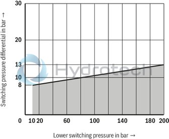
All variants can be unloaded to pmin = 0 bar. (Observe the switching pressure differential!)
For applications outside these parameters, please consult us!
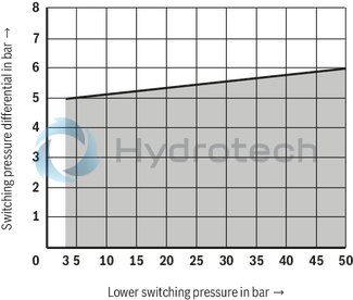
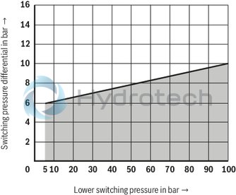
Switching pressure differential (measured with HLP46, ϑOil = 40 ±5 °C)
Pressure rating 50 bar
Pressure rating 100 bar
Pressure rating 200 bar
Pressure rating 350 bar
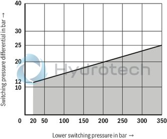
Notice:
The switching pressure differential may increase within the course of the life cycle due to the deterioration of the oil quality and the number of load cycles.

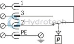
|
"K14" without indicator light |
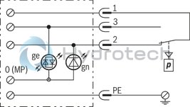
"K14" with indicator light |
 |
 |
|
Switching function Terminals 1-2: Contact opens in case of pressure increase Terminals 1-3: Contact closes in case of pressure increase |
|
Notice:
For general information on safety, installation or commissioning, see operating instructions.
Type HED 5 …K14
Dimensions in mm
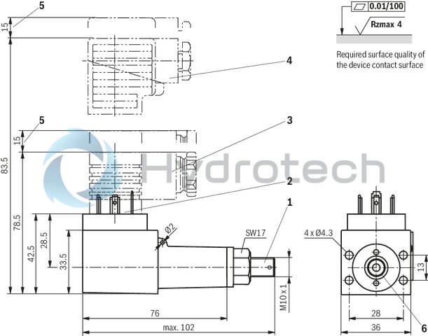
|
1 |
Adjustment element |
|
2 |
Plug-in connection according to EN 175301-803 (port “K14”) |
|
3 |
Mating connector without circuitry (separate order) |
|
4 |
Mating connector with circuitry (separate order) |
|
5 |
Space required to remove the mating connector |
|
6 |
Seal ring (connection bore of the counterpart: max. Ø6) |
Mounting screws (separate order)
4 hexagon socket head cap screws ISO 4762-M4X45-10.9-flZn-240h-L
(friction coefficient μtotal = 0.09 to 0.14)
Tightening torque MA = 2 Nm ± 10 %
Material no. R913000370
Mating connectors for mechanical pressure switches with connector “K14”, without circuitry, standard
4P Z14
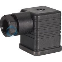
Mating connectors for mechanical pressure switches with connector “K14”, without circuitry, standard
4P Z14
For mechanical pressure switches with connector “K14”, according to EN 175301-803 and ISO 4400, 3-pole + PE, “large cubic connector”Data sheet
Spare parts & repair
Mating connectors for mechanical pressure switches with connector “K14”, with indicator lights at connections 2 and 3
4P Z15L
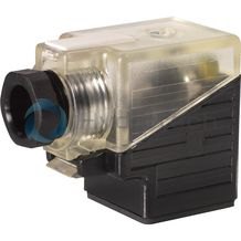
Mating connectors for mechanical pressure switches with connector “K14”, with indicator lights at connections 2 and 3
4P Z15L
For mechanical pressure switches with connector “K14”, according to EN 175301-803 and ISO 4400, 3-pole + PE, “large cubic connector”Data sheet
Spare parts & repair
Mating connectors for sensors and valves with connector “K24”, “K35” and “K72”, M12 x 1
4P Z24
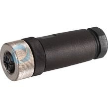
Mating connectors for sensors and valves with connector “K24”, “K35” and “K72”, M12 x 1
4P Z24
For sensors and valves with connector “K24”, “K35” and “K72” Mating connectors M12, 4-pole, line cross-section 0.75 mm2Data sheet
Spare parts & repair