
BOSCH REXROTH
3DREM10P-7X/200YG24K4V
R901218236
Proportional Pressure Reducing Control Valves
Prop.press.valves: 3DRE* 10.-7x/
BOSCH REXROTH
MATERIAL: R901218236
SUMMARY: Prop.press.valves: 3DRE* 10.-7x/
Quantity in stock: 0
The valves of type 3DRE(M) are electrically pilot-operated 3-way pressure reducing valves with pressure
limitation of the actuator. They are used for reducing a system pressure.
Technical set-up
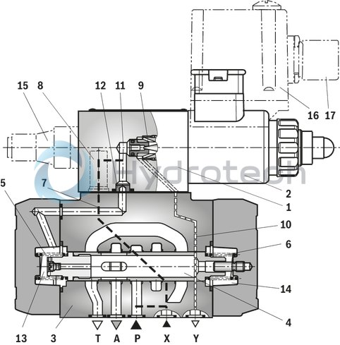
The valve consists of two main assemblies:
Pilot control valve (1) with proportional solenoid (2) optionally with maximum pressure limitation (15) Main valve (3) with main spool (4)
Function
General function:
Command value-dependent setting of the pressure to be reduced in port A via the pilot control valve (1). With depressurized port P, the springs (5) and (6) hold the main spool (4) in its central position. In this way, a start-up jump at the actuator is prevented. Pilot oil flows from bore (7) via the flow controller (8), via the control chamber (11) to the throttle gap (9), via line (10) to port Y. This connection is to be lead into the tank at zero pressure.
Pressure reduction:
Build-up of the pilot pressure in the control chamber (11) as a function of the command value. Pressure build-up in the spring chamber (13) via nozzle (12) and movement of the main spool (4) to the right. Hydraulic fluid flows from P to A. The actuator pressure in port A is available in the spring chamber (14). Increase in the pressure in port A to the set pressure of the pilot control valve (1) leads to the movement of the main spool (4) to the left. Pressure in port A is almost identical with the set pressure at the pilot control valve (1).
Pressure limitation:
If the pressure in port A exceeds the set pressure of the pilot control valve (1), the main spool (4) is moved further to the left. This opens the connection from A to T and limits the pressure pending in port A to the set command value.
Type 3DREM
For hydraulic protection against an inadmissibly high electric control current at the proportional solenoid, which imperatively results in increased pressures in port A, you can optionally install a spring-loaded pressure relief valve as maximum pressure limitation (15).
The maximum pressure limitation is pre-set based on the relevant pressure rating.
Pilot oil supply
|
3DRE...-.../...XY... |
External pilot oil supply Pilot oil return, external |
In this version, the pilot oil is supplied from a separate control circuit (external).The pilot oil return is not directed into channel T of the main valve, but is separately directed to the tank via port Y (external). |
|
3DRE...-.../...Y... |
Internal pilot oil supply Pilot oil return, external |
With this version, the pilot oil is supplied from channel P of the main valve (internally).The pilot oil return is not directed into channel T of the main valve, but is separately directed to the tank via port Y (external).In the subplate, port X is to be closed. |
|
NG10 |
NG10; sectional diagram see Dimensions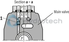 |
Position 1: Plug screw M6 DIN 906-8.8 SW 3 |
|
NG16 |
NG16; sectional diagram see Dimensions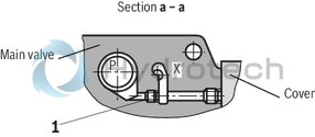 |
|
01 |
02 |
03 |
04 |
05 |
06 |
07 |
08 |
09 |
10 |
11 |
12 |
||
|
3DRE |
P |
- |
7X |
/ |
G24 |
K4 |
V |
* |
|
01 |
Proportional pressure reducing valve, pilot-operated, with external control electronics, 3-way version |
3DRE |
|
02 |
Without maximum pressure limitation |
no code |
|
With maximum pressure limitation |
M |
|
|
03 |
Size 10 |
10 |
|
Size 16 |
16 |
|
|
04 |
Subplate mounting |
P |
|
05 |
Component series 70 … 79 (70 … 79: unchanged installation and mounting dimensions) |
7X |
|
Pressure rating |
||
|
06 |
Up to 50 bar |
50 |
|
Up to 100 bar |
100 |
|
|
Up to 200 bar |
200 |
|
|
Up to 250 bar (NG16 only) |
250 |
|
|
Up to 315 bar (NG16 only) |
315 |
|
|
07 |
Internal pilot oil supply, external pilot oil return |
Y |
|
External pilot oil supply, external pilot oil return |
XY |
|
|
Power supply |
||
|
08 |
Direct voltage 24 V |
G24 |
|
09 |
1600 mA coil |
no code |
|
800 mA coil |
-8 |
|
|
Electrical connection |
||
|
10 |
Without mating connector; connector DIN EN 175301-803 |
K4 |
|
Seal material |
||
|
11 |
NBR seals |
M |
|
FKM seals |
V |
|
|
12 |
Further details in the plain text |
* |
For applications outside these parameters, please consult us!
general
|
Type |
3DRE(M) | ||
|
Size |
10 | 16 | |
|
Component series |
7X | ||
|
Installation position |
any, preferably horizontal | ||
|
Weight |
kg |
7.5 | 10.3 |
|
Storage temperature range |
°C |
-20 … +80 | |
|
Ambient temperature range |
°C |
-20 … +70 | |
hydraulic
|
Type |
3DRE(M) | |||
|
Size |
10 | 16 | ||
|
Maximum operating pressure |
bar |
350 | 315 | |
|
Maximum operating pressure |
Port P |
bar |
350 | 315 |
|
Port A |
bar |
315 | 250 | |
|
Port T |
bar |
315 | 250 | |
|
Port X |
bar |
350 | 315 | |
|
Port Y |
separate and depressurized to the tank | |||
|
Maximum set pressure in port A |
Pressure rating 50 bar |
bar |
50 | |
|
Pressure rating 100 bar |
bar |
100 | ||
|
Pressure rating 200 bar |
bar |
200 | ||
|
Pressure rating 250 bar |
bar |
250 | ||
|
Pressure rating 315 bar |
bar |
315 | ||
|
Minimum set pressure 1) |
bar |
< 5 | < 4 | |
|
Maximum pressure relief function |
Pressure rating 50 bar 2) |
bar |
70 | |
|
Pressure rating 100 bar |
bar |
130 | ||
|
Pressure rating 200 bar |
bar |
230 | ||
|
Pressure rating 250 bar |
bar |
270 | ||
|
Pressure rating 315 bar |
bar |
350 | ||
|
Pilot flow |
l/min |
1.1 | ||
|
Maximum flow |
l/min |
125 | 300 | |
|
Hydraulic fluid |
see table | |||
|
Hydraulic fluid temperature range |
°C |
-20 … +80 | ||
|
Viscosity range |
mm²/s |
15 … 380 | ||
|
Maximum admissible degree of contamination of the hydraulic fluid, cleanliness class according to ISO 4406 (c) 3) |
Class 20/18/15 according to ISO 4406 (c) | |||
|
Hysteresis 4) |
% |
± 3 | ||
|
Repetition accuracy 4) |
% |
< ± 2 | ||
|
Linearity 4) |
% |
± 3.5 | ||
|
Manufacturing tolerance of the command value pressure characteristic curve 4) |
at command value 20 % |
% |
< ± 1.5 | |
|
at command value 100 % |
% |
< ± 5 | ||
|
Step response 5) |
10 ... 90% |
ms |
< 140 | |
| 1) | In channel A without flow, with command value 0 (see characteristic curves) |
| 2) | set at the factory |
| 3) | The cleanliness classes specified for the components must be adhered to in hydraulic systems. Effective filtration prevents faults and simultaneously increases the life cycle of the components. For the selection of the filters, see www.boschrexroth.com/filter. |
| 4) | Of the maximum set pressure |
| 5) | measured with standing hydraulic fluid column, 1.0 liters at port A |
|
Hydraulic fluid |
Classification |
Suitable sealing materials |
Standards |
|
Mineral oils and related hydrocarbons |
HL, HLP |
NBR / FKM |
DIN 51524 |
|
Important information on hydraulic fluids: For more information and data on the use of other hydraulic fluids please contact us. The flash point of the process and operating medium used must be 40 K over the maximum solenoid surface temperature.
Flame-resistant - containing water: Bio-degradable: When using hydraulic fluids that are simultaneously zinc-solving, zinc may accumulate (700 mg zinc per pole tube). |
|||
electrical
|
Type |
3DRE(M) | |||
|
Minimum solenoid current |
with 1600 mA - coil |
mA |
≤ 100 | |
|
with 800 mA - coil |
mA |
≤ 100 | ||
|
Maximum solenoid current |
with 1600 mA - coil |
mA |
1760 | |
|
with 800 mA - coil |
mA |
840 | ||
|
Solenoid coil resistance |
Cold value at 20 °C |
with 1600 mA - coil |
Ω |
5.5 |
|
with 800 mA - coil |
Ω |
20.6 | ||
|
Solenoid coil resistance |
Maximum hot value |
with 1600 mA - coil |
Ω |
8.05 |
|
with 800 mA - coil |
Ω |
33 | ||
|
Duty cycle |
% |
100 | ||
measured with HLP46, ϑOil = 40 ±5 °C, valve body and hydraulic fluid temperature-compensated.
Large temperature differences may lead to differing characteristic curves / values.
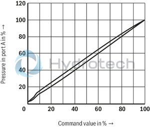
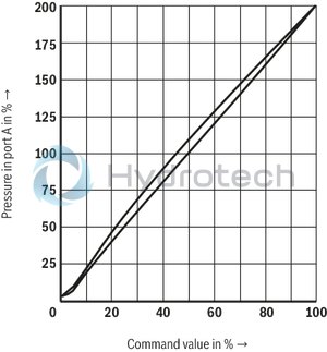
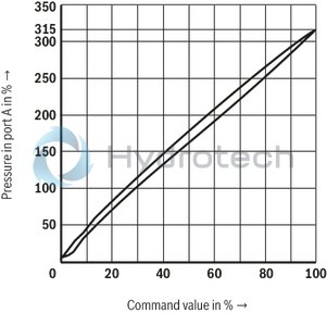
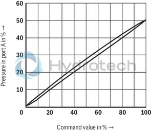
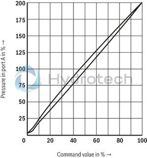
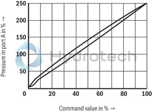
Pressure in port P dependent on the command value
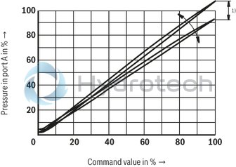
| 1) | 1) With valve type DBEM and 3DREM, the manufacturing tolerance at the external amplifier can be changed using the command value attenuator potentiometer "Gw”. The digital amplifier is set using the "Limit” parameter. Here, the control current according to the technical data must not be exceeded. In order to be able to adjust several valves to the same characteristic curve, do not set the pressure higher than the maximum set pressure of the pressure rating with command value 100%. |
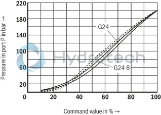
Pressure dependent on the command value / comparison G24 and G24-8 / pressure rating 200 bar (with amplifier VT-VSPA1-1-1X with 800 mA coil)
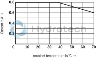
Current drop with increasing ambient temperature, 24 V and 100% duty cycle
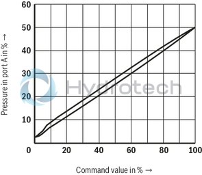
Pressure rating 50 bar
Size 10
Pressure rating 100 bar
Size 10
Pressure rating 200 bar
Size 10
Pressure rating 315 bar
Size 10
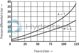
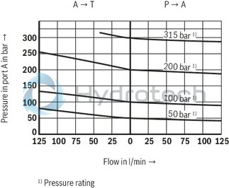
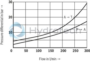
Pressure differential dependent on the flow
Size 10
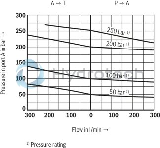
Pressure in port A dependent on the flow
Size 10
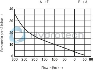
Minimum set pressure dependent on the flow at command value 0
Size 10

Pressure rating 50 bar
Size 16
Pressure rating 100 bar
Size 16

Pressure rating 200 bar
Size 16
Pressure rating 250 bar
Size 16
Pressure differential dependent on the flow
Size 16
Pressure in port A dependent on the flow
Size 16
Minimum set pressure dependent on the flow at command value 0
Size 16
Type 3DRE...Y...

Type 3DREM...Y...

Type 3DRE...XY...

Type 3DREM...XY...

Connection at mating connector

Connection at the connector

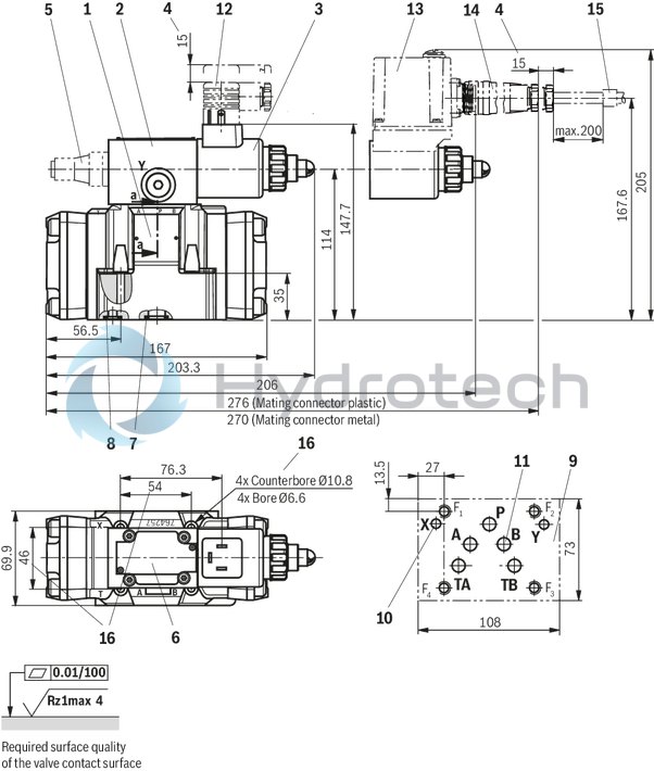
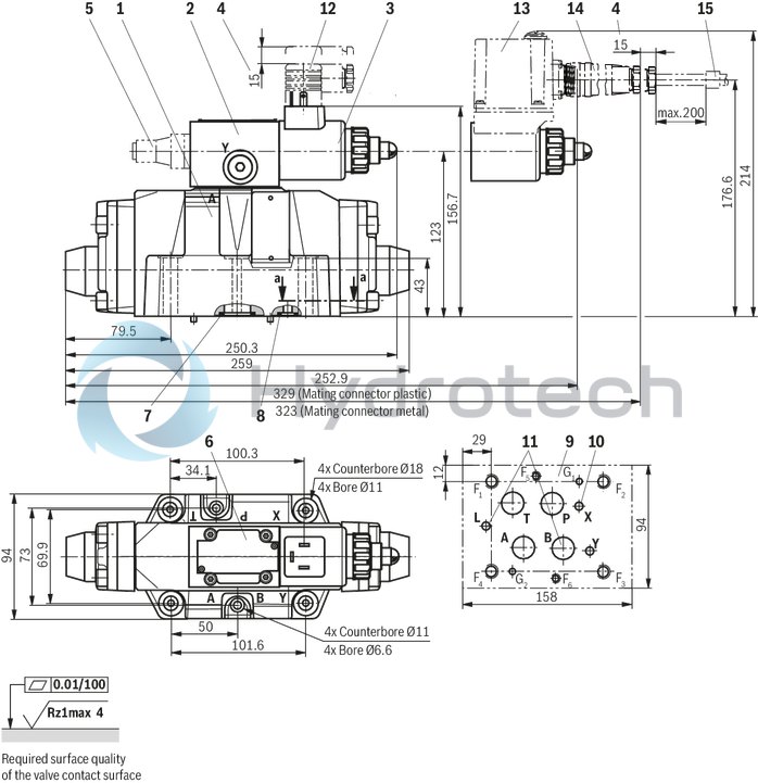
|
1 |
Main valve |
|
2 |
Pilot control valve |
|
3 |
Proportional solenoid |
|
4 |
Space required to remove the mating connector |
|
5 |
Maximum pressure limitation (type 3DREM…) |
|
6 |
Name plate |
|
7 |
Identical seal rings for port A, B, P, TA, TB |
|
8 |
Identical seal rings for ports X and Y |
|
9 |
Machined valve contact surface; Porting pattern according to DIN 24340-A10 and ISO 4401-05-05-0-05 |
|
10 |
With “internal” pilot oil supply (version Y), port X in the subplate must be closed. |
|
11 |
Port B must be closed in the subplate |
|
12 |
mating connector according to DIN EN 175301-803 |
|
13 |
Integrated electronics (type 3DREE, 3DREME) with connector |
|
14 |
Mating connector according to DIN EN 175201-804 |
Recommended valve mounting screws (separate order):
4 hexagon socket head cap screws ISO 4762 - M6 x 45 - 10.9-flZn-240h-L
(Friction coefficient μtotal = 0.09 to 0.14)
Tightening torque MA = 12.5 Nm ± 10%
material no. R913000258
or
4 hexagon socket head cap screws ISO 4762 - M6 x 45 - 10.9
(Friction coefficient μtotal = 0.12 to 0.17)
Tightening torque MA = 15.5 Nm ± 10%
material no. R900003263
|
1
|
Main valve |
|
2
|
Pilot control valve |
|
3
|
Proportional solenoid |
|
4
|
Space required to remove the mating connector |
|
5 |
Maximum pressure limitation (type 3DREM…) |
|
6
|
Name plate |
|
7
|
Identical seal rings for ports A, B, P, and T |
|
8
|
Identical seal rings for ports X and Y |
|
9 |
Machined valve contact surface; Porting pattern according to DIN 24340-A16 and ISO 4401-05-07-0-05 |
|
10 |
With “internal” pilot oil supply (version Y), port X in the subplate must be closed. |
|
11 |
Ports B and L must be closed in the subplate |
|
12 |
mating connector according to DIN EN 175301-803 |
|
13 |
Integrated electronics (type 3DREE, 3DREME) with connector |
|
14 |
Mating connector according to DIN EN 175201-804 |
Recommended valve mounting screws (separate order):
2 hexagon socket head cap screws ISO 4762 - M6 x 60 - 10.9-flZn-240h-L
(Friction coefficient μtotal = 0.09 to 0.14)
Tightening torque MA = 12.2 Nm ± 10%
Material no. R913000115
4 hexagon socket head cap screws ISO 4762 - M10 x 60 - 10.9-flZn-240h-L
(Friction coefficient μtotal = 0.09 to 0.14)
Tightening torque MA = 59 Nm ± 10%
Material no. R913000116
or
2 hexagon socket head cap screws ISO 4762 - M6 x 60 - 10.9
(Friction coefficient μtotal = 0.12 to 0.17)
Tightening torque MA = 15.5 Nm ± 10%
Material no. R900003266
4 hexagon socket head cap screws ISO 4762 - M10 x 60 - 10.9
(Friction coefficient μtotal = 0.12 to 0.17)
Tightening torque MA = 75 Nm ± 10%
Material no. R900008630
Notice:
The dimensions are nominal dimensions which are subject to tolerances.
Mating connectors for valves with connector “K4”, without circuitry, standard
3P Z4
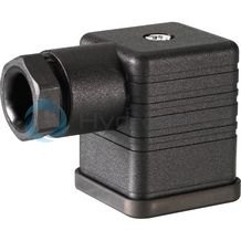
Mating connectors for valves with connector “K4”, without circuitry, standard
3P Z4
For valves with connector “K4” according to EN 175301-803 and ISO 4400, 2-pole + PE, “large cubic connector” Mating connectors for valves with one or two solenoids (individual connection)Data sheet
Spare parts & repair