
BOSCH REXROTH
DA6VA2B5X/350FSM
R901224228
Pressure Cut-off Pressure Valves
Pressure valves: DA 6 V.-5x/
BOSCH REXROTH
MATERIAL: R901224228
SUMMARY: Pressure valves: DA 6 V.-5x/
Quantity in stock: 0
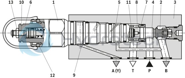
The pressure valve type DA 6 V is a pilot-operated pressure cut-off valve with steplessly adjustable switching pressure differential. It basically consists of pilot control stage and main stage of the screw-in cartridge valve (1), check valve (2) and housing (3).
The pump flow in P is introduced into the accumulator of the system via port B. If the pressure at the actuator in port B exceeds the set top switching pressure, the pilot control valve opens and pilot fluid discharge is enabled via port A (Y). The check valve (2) closes the connection from port B to port P and the pump flow is switched to depressurized circulation (from P to T).
Type DA 6 VP
Switching of the pump flow from P to B (pump → actuator) to P to T (pump → tank).The pump delivers via the check valve (2) into the hydraulic system (P to B). The pressure in channel B acts via the control line (4) and the bore (5) on the pilot control of the screw-in cartridge valve (1). Simultaneously, the pressure in channel P is applied via the bore (7) to the spring-loaded side of the main spool (8). As soon as the top cut-off pressure set via the adjustment spindle (6) in the screw-in cartridge valve (1) is reached in the hydraulic system (channel B), pilot control of the screw-in cartridge valve (1) opens the connection from the spring-loaded side of the main spool (8) to the control line (9) and the external connection via port A (Y) into the tank. Due to the bore (7), a pressure drop occurs at the main spool (8). The main spool (8) is lifted from the seat and opens connection P to T. The check valve (2) closes the connection B to P and pilot control of the screw-in cartridge valve (1) is held in open position by the actuator pressure in B.
Switching of the pump flow from P to T (pump → tank) to P to B (pump → actuator).If the actuator pressure in B compared to the cut-off pressure has fallen according to the lower bottom pressure value set at the adjustment spindle (10), pilot control of the screw-in cartridge valve (1) is set back to its initial position.
This way, a pressure is built up on the spring-loaded side of the main spool (8). It closes the connection from P to T by means of the spring (11) and the pump delivers via the check valve (2) into the hydraulic system from P to B.
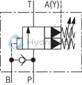
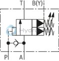
Type DA 6 VA
At this valve type, the pump connection is not designed in P but in A. The valve directs the pump flow from A to P or from A to T. The drain port is located in B (Y).
The switching processes correspond to version "VP" (this valve version supports connection with manifolds).
Type DA 6 VP…
Notices!
Only indirect pressure limiting function:A pressure limiting function of the pump pressure (to the tank) is not directly provided but only indirectly via the check valve (2) and the control line (4) in the actuator channel.
Setting the switching pressure differential:At the factory, the valves are set at nominal pressure to a switching pressure differential of approx. 10 % to 12 %. A setting of 50 % of the nominal pressure is possible.
On delivery, the adjustment spindle (6) is set to the minimum adjustable top switching pressure, i.e., the adjustment spindle (6) is screwed out up to the limit stop.
By screwing in the adjustment spindle (6), the top switching pressure may be increased.
By screwing in the adjustment spindle (10), the bottom switching pressure is increased and the switching pressure differential reduced. Screwing out the adjustment spindle (10) reduced the bottom switching pressure and the switching pressure differential is increased.
The pressure adjustment is secured via a clamping screw (12) and a lock nut (13).
|
01 |
02 |
03 |
04 |
05 |
06 |
07 |
08 |
09 |
10 |
11 |
12 |
|
|
DA |
6 |
V |
2 |
5X |
/ |
FS |
* |
|
01 |
Pressure cut-off valve |
DA |
|
02 |
Size 6 |
6 |
|
03 |
pilot operated |
V |
|
04 |
Pump connection in channel P (standard) |
P |
|
Pump connection in channel A |
A |
|
|
Adjustment type |
||
|
05 |
Sleeve with hexagon and protective cap |
2 |
|
06 |
Adjustment on side A |
A |
|
Adjustment on side B |
B |
|
|
07 |
Component series 50 … 59 (50 … 59: unchanged installation and connection dimensions) |
5X |
|
Pressure range |
||
|
08 |
25 to 50 bar |
50 |
|
50 to 100 bar |
100 |
|
|
100 to 200 bar |
200 |
|
|
150 to 350 bar |
350 |
|
|
09 |
freely adjustable switching pressure differential |
FS |
|
Seal material |
||
|
10 |
NBR seals |
M |
|
FKM seals (other seals upon request) |
V |
|
|
Observe compatibility of seals with hydraulic fluid used. |
||
|
11 |
Without locating hole |
no code |
|
With locating hole |
/60 1) |
|
|
With locating hole and locking pin ISO 8752-3x8-St |
/62 |
|
|
12 |
Further details in the plain text |
* |
| 1) Locking pin ISO 8752-3 x 8-St, material no. R900005694 (separate order) |
Preferred types and standard units are specified in the EPS (standard price list).
general
|
Size |
6 | ||
|
Weight |
kg |
2.2 | |
|
Installation position |
any | ||
|
Ambient temperature range |
NBR seals |
°C |
-30 … +80 |
|
FKM seals |
°C |
-20 … +80 | |
hydraulic
|
Size |
6 | |||
|
Type |
Type "DA 6 VP" | Type "DA 6 VA" | ||
|
Maximum operating pressure |
Port "A" (Y) (leakage pilot control) 1) |
bar |
100 - |
- - |
|
Port "B" (actuator) 2) |
bar |
350 - |
- - |
|
|
Port "P" (pump) |
bar |
350 - |
- - |
|
|
Port "T" (tank) |
bar |
200 - |
- - |
|
|
Port "A" (pump) |
bar |
- | 350 | |
|
Port "B" (Y) (leakage pilot control) |
bar |
- | 100 | |
|
Port "P" (actuator) |
bar |
- | 350 3) | |
|
Port "T" (tank) |
bar |
- | 200 | |
|
Set pressure range |
Pressure rating 50 bar |
bar |
25 … 50 | |
|
Pressure rating 100 bar |
bar |
50 … 100 | ||
|
Pressure rating 200 bar |
bar |
100 … 200 | ||
|
Pressure rating 350 bar |
bar |
150 … 350 | ||
|
Switching pressure differential |
adjustable from 10 % to 50 % of the nominal value | |||
|
Maximum flow |
l/min |
40 | ||
|
Hydraulic fluid |
see table | |||
|
Hydraulic fluid temperature range |
FKM seals |
°C |
-30 … +80 | |
|
FKM seals |
°C |
-20 … +80 | ||
|
Viscosity range |
Maximum |
mm²/s |
10 … 800 | |
|
Recommended |
mm²/s |
20 … 60 | ||
|
Maximum admissible degree of contamination of the hydraulic fluid 4) |
Class 20/18/15 according to ISO 4406 (c) | |||
| 1) | Attention! The applied pressure adds to the set pressure! The switching pressure differential remains unchanged within the setting range! |
| 2) | (after switching P to T) |
| 3) | (after switching A to T) |
| 4) | The cleanliness classes specified for the components must be adhered to in hydraulic systems. Effective filtration prevents faults and simultaneously increases the life cycle of the components. For the selection of the filters, see www.boschrexroth.com/filter. |
|
Hydraulic fluid |
Classification |
Suitable sealing materials |
Standards |
|
|
Mineral oil |
HL, HLP |
FKM, NBR |
DIN 51524 |
|
|
Bio-degradable |
Insoluble in water |
HEES (synthetic esters) |
FKM |
VDMA 24568 |
|
HETG (rape seed oil) |
FKM, NBR |
|||
|
Soluble in water |
HEPG (polyglycols) |
FKM |
VDMA 24568 |
|
|
Other hydraulic fluids on request |
||||
For applications outside these parameters, please consult us!
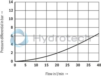
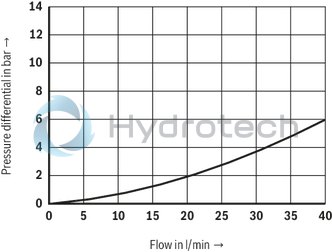
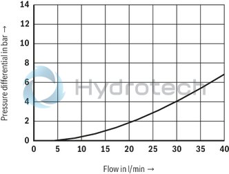
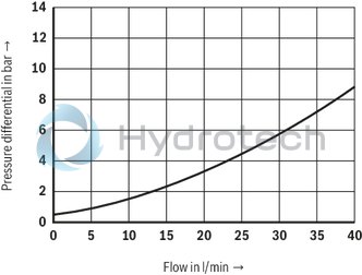
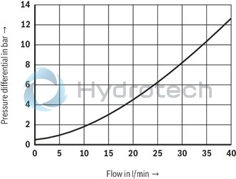
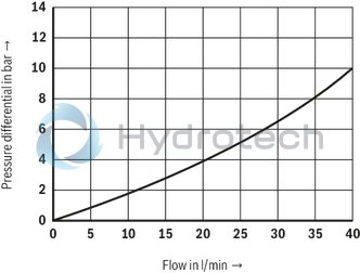
(measured with HLP46, ϑOil = 40 ±5 °C)
Version "VP2A"
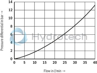
Δp-qV characteristic curves, circulation pressure – version "VP" (P to T)

Version "VP2B"
Δp-qV characteristic curves, circulation pressure – version "VP" (P to T)
Version "VA2A"
Δp-qV characteristic curves, circulation pressure – version "VA" (A to T)
Version "VA2B"
Δp-qV characteristic curves, circulation pressure – version "VA" (A to T)
Notice!
The characteristic curves were measured with external, depressurized pilot oil return (circulation pressure). The characteristic curves apply for outlet pressure = 0 bar in the entire flow range!Version "VP2A"
Δp-qV characteristic curves via check valve – version "VP" (P to B)
Version "VP2B"
Δp-qV characteristic curves via check valve – version "VP" (P to B)
Version "VA2A"
Δp-qV characteristic curves via check valve – version "VA" (A to T)
Version "VA2B"
Δp-qV characteristic curves via check valve – version "VA" (A to T)
Notice!
The characteristic curves were measured with external, depressurized pilot oil return (circulation pressure). The characteristic curves apply for outlet pressure = 0 bar in the entire flow range!Version "VP"
Version “VA”
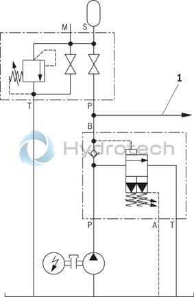
Hydraulic system with pressure accumulator
Type DA 6 VP…
Hydraulic system with high- and low-pressure pump
Type DA 6 VP…
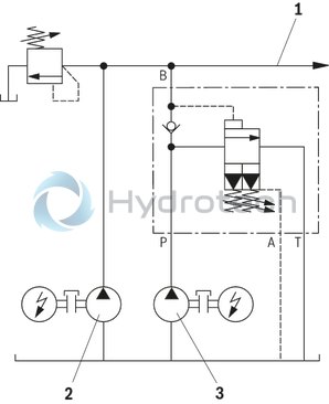
|
1 |
to actuator |
|
2 |
High-pressure pump |
|
3 |
Low-pressure pump |
Application note:
Establish a short and low-resistance connection between pressure cut-off valve and hydraulic accumulator.
Attention!
Accumulators may only be operated with suitable accumulator safety equipment! A pressure limiting function of the pump pressure (to the tank) is not directly provided but only indirectly via the check valve and the control line in the actuator channel (see functional description).Version "2A"
Dimensions in mm
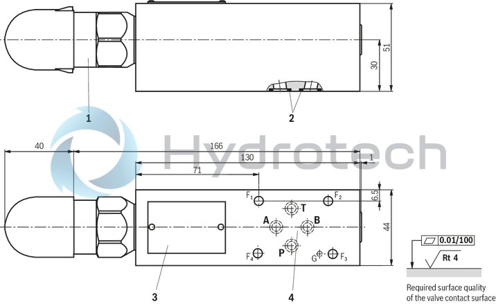
|
1 |
Adjustment type "2" |
|
2 |
Identical seal rings for connection A, B, P, T |
|
3 |
Name plate |
|
4 |
Porting pattern according to ISO 5781-03-04-0-00 (with locating hole for locking pin ISO 8752-3 x 8-St, material no. R900005694, separate order); not in compliance with the standard, also without locating hole |
Subplates (separate order)
Without locating holeG 341/01 (G1/4)
G 342/01 (G3/8)
G 502/01 (G1/2)
with locating holeG 341/60 (G1/4)
G 342/60 (G3/8)
G 502/60 (G1/2)
Valve mounting screws (separate order)
4 x ISO 4762 - M5 x 60 - 10.9-flZn-240h-L
at friction coefficient μtotal = 0.09 to 0.14,
Tightening torque MA = 7 Nm ± 10 %,
material no. R913000319
Version "2B"
Dimensions in mm
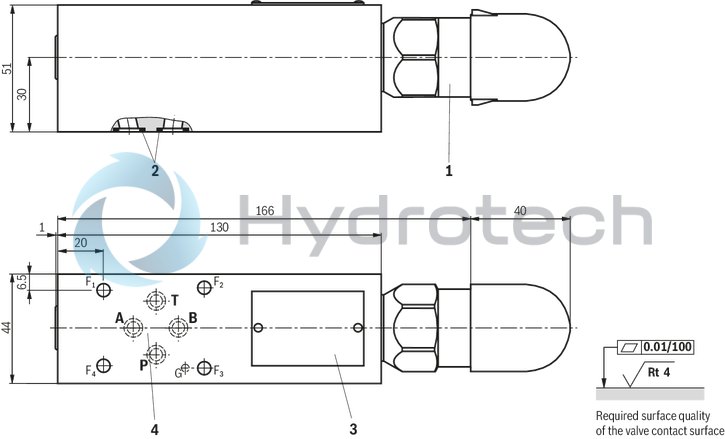
|
1 |
Adjustment type "2" |
|
2 |
Identical seal rings for connection A, B, P, T |
|
3 |
Name plate |
|
4 |
Porting pattern according to ISO 5781-03-04-0-00 (with locating hole for locking pin ISO 8752-3 x 8-St, material no. R900005694, separate order); not in compliance with the standard, also without locating hole |
Notice: Switching pressure differential factory settings
At the factory, the valves are set at nominal pressure to a switching pressure differential of approx. 10 % to 12 % and are supplied in a depressurized state (adjustment spindle (6) screwed out up to the at limit stop, see product description). Adjustment is realized at nominal pressure, a pump flow of approx. 10 l/min and an actuator flow of approx. 2 l/min. Different system conditions (particularly high pump and actuator flows) may lead to higher switching pressures. Here, the valve offers the possibility of optional adjustment of the switching pressure differential to the system.