
BOSCH REXROTH
R901247789
Level Sensors
Level display & meas. equipments (Std)
BOSCH REXROTH
MATERIAL: R901247789
SUMMARY: Level display & meas. equipments (Std)
Quantity in stock: 0
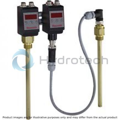
Electronic contact thermometers are used for the temperature control of hydraulic systems.
The contact thermometers have two or four programmable temperature switching outputs, or alternatively one programmable switching output and one analog output 4 … 20 mA, with display and control unit.
The temperature display can be selected in °C or °F.
Display and control unit function
The micro-processor controlled display and control unit processes the analog input signals for the analysis of the temperature control. The temperature can be set at the control unit in an easy menu navigation by means of pushbuttons and the settings can be read off at the LED display.
The display and control unit has a four-digit, red seven-segment LED display and 3 pushbuttons for the operation as well as up to 4 LEDs integrated in the front plate for the display of alarm conditions.
The device moreover has two (t2) and/or four (T4) freely adjustable PNP switching outputs plus the adjustable switch-back points. One PNP output can be programmed as frequency output. Alternatively one freely programmable PNP switching output and one 4 ... 20 mA output for the continuous temperature measurement. The switching conditions are shown in the display which can be rotated by 270° (version D0).
The output 4 … 20 mA can optionally be set to 0 … 10 V, 2 … 10 V or 0 … 5V.
Depending on the setting for the measured temperature, the desired unit (°C, °F) will be displayed. By default, the temperature display is set to °C.
During the setting and/or programming of the corresponding process parameters, the parameter values and/or the related menu items are shown in the display. In case of energy supply failure, all input values will be stored, the max/min values can be called from a permanent memory, if necessary.
Parameterization
The menu navigation is based on the VDMA standard sheet for fluid sensors 24574-1.
The operating menu is designed hierarchically as tree structure.
That means that frequently used functions and adjustment points are quickly accessible and rarely used menu items can be found in a submenu.
Using the ▲ and ▼ keys, the corresponding parameters are set and/or the next menu item is displayed.
Using the ► key, the selected menu item is selected and/or the set parameter is accepted and stored.
The parameter may be a numerical value and a selection of functions (e.g. NO [output as normally open contact], NC [output as normally closed contact] or i1 [analog output 4 … 20 mA]).
After confirmation of a parameter or function selection by means of the ► key, the display will switch back to the current menu item. Then, you can use ▲ and ▼ to display the next menu item and the ► key to select it.
Ordering code
|
01 |
02 |
03 |
04 |
05 |
06 |
07 |
08 |
||||
|
ABZM |
T |
‒ |
1X |
/ |
/ |
‒ |
K24 |
|
Power unit accessories |
||
|
01 |
Measuring devices |
ABZM |
|
02 |
Electronic contact thermometer |
T |
|
03 |
Component series 10 ... 19 (10 ... 19: unchanged installation and connection dimensions) |
1X |
|
Sensor length in mm |
||
|
04 |
L = 200 mm |
0200 |
|
L = 300 mm |
0300 |
|
|
L = 500 mm |
0500 |
|
|
L = 1000 mm |
1000 |
|
|
Sensor |
||
|
05 |
Brass MS (with NBR seal) |
MS |
|
Stainless steel 1.4571 (with FKM seal) |
ES |
|
|
Display and control unit |
||
|
06 |
Directly attached display and control unit |
D0 |
|
External display and control unit with cable set M12 x 1; 4-pole, PUR |
||
|
1500 mm, mating connector angled and line connector straight |
E1 |
|
|
3000 mm, mating connector angled and line connector straight |
E3 |
|
|
5000 mm, mating connector angled and line connector straight |
E5 |
|
|
Temperature |
||
|
07 |
Temperature display and two programmable switching outputs |
T2 |
|
Temperature display and four programmable switching outputs |
T4 |
|
|
Temperature display, one programmable switching output and one analog output 4 … 20 mA |
T1A |
|
|
Electrical connection 1) |
||
|
08 |
Connector, 4-pole M12 x 1 |
K24 |
| 1) | The mating connectors are not included in the scope of delivery and must be ordered separately, if required (see R.08006). |
| Order example: | |
| Electronic contact thermometer, sensor length 300 mm, sensor in brass, directly attached control and indicator unit, temperature display and two programmable switching outputs, connector K24: | |
| ABZMT-1X/0300MS/D0-T2-K24 |
electrical
|
Plug-in connection |
4-pole M12 x 1 (material: metal) |
Temperature sensor Pt100
|
Sensor element |
Pt100 class B DIN EN 60751 | |
|
Temperature measuring range |
°C |
0 … 100 |
|
Accuracy |
K |
± 0.8 |
Display and control unit
|
Power supply |
V DC |
10 … 32 | |
|
Maximal contact load |
A |
1 | |
|
Display range |
°C |
-20 … +120 | |
|
Alarm adjustment range |
°C |
0 … 100 | |
|
Housing design |
PA, IP65 (antistatisch) | ||
|
Current consumption upon switch-on |
more than 100 ms |
mA |
≈ 100 |
|
Current consumption during operation |
with UB 24 V |
mA |
≈50 |
|
Operation |
3 keys | ||
Version T2
|
Switching points |
2 programmable switching outputs | ||
|
Maximum switching current |
per output |
A |
0.5 |
|
Total |
A |
1 | |
Version T4
|
Switching points |
4 programmable switching outputs | ||
|
Maximum switching current |
per output |
A |
0.5 |
|
Total |
A |
1 | |
Version T1A
|
Switching points |
1 programmable switching output | ||
|
Maximum switching current |
per output |
A |
0.5 |
|
Total |
A |
1 | |
|
Output signal 1) |
mA |
4 … 20 | |
|
Maximum load |
Ω |
500 | |
|
Mounting of external display and control unit |
Assembly on top hat rail 35 mm | ||
| 1) | Alternatively 0 … 10, 2 … 10 or 0 … 5 V adjustable |
Resistance
|
Hydraulic fluids |
Seals |
||||
|
NBR |
FKM |
||||
|
Mineral oils |
Mineral oil |
HL/HLP |
according to DIN 51524 |
Resistant |
Resistant |
|
Flame-resistant hydraulic fluids |
Emulsions |
HFA-E |
according to DIN 24320 |
Not resistant |
|
|
Water solutions |
HFC |
according to VDMA 24317 |
Not resistant |
||
|
Phosphoric acid esters |
HFD-R |
||||
|
Organic esters |
HFD-U |
Resistant |
|||
|
Fast bio-degradable hydraulic fluids |
Triglycerides (rape seed oil) |
HETG |
according to VDMA 24568 |
||
|
Synthetic esters |
HEES |
Not resistant |
|||
|
Polyglycols |
HEPG |
||||
For applications outside these parameters, please consult us!
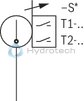
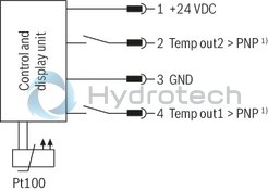
Two programmable switching outputs for temperature (T2)
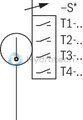
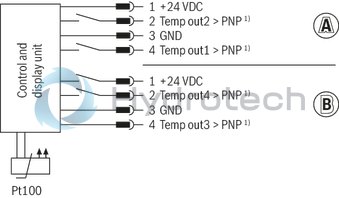
Four programmable switching outputs for temperature (T4)
One programmable switching output and one analog output 4 … 20 mA for temperature (T1A)
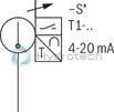
Pinout
Switching function plug-in connection M12 x 1|
Version |
T2 |
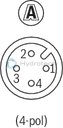 |
|
Connector B not available |
||
|
T4 |
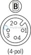 |
 |
||||
|
T1A |
|
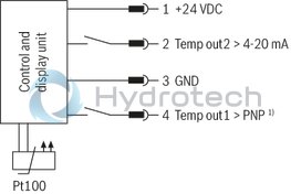
|
Connector B not available |
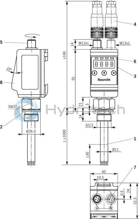
Dimensions: Directly attached display and control unit
(version D)Dimensions in mm
|
1 |
Immersion depth at least 30 mm |
|
2 |
Profile seal G1/2 |
|
3 |
Name plate |
|
4 |
Mating connector for plug-in connections K24 (M12 x 1), see table "Mating connector" |
|
5 |
Connector K24; 4-pole M12 x 1 |
|
6 |
LEDs for the display of alarm switching points |
|
7 |
Connector B only with version T4 |
|
8 |
Display and control unit can be rotated by 270° |
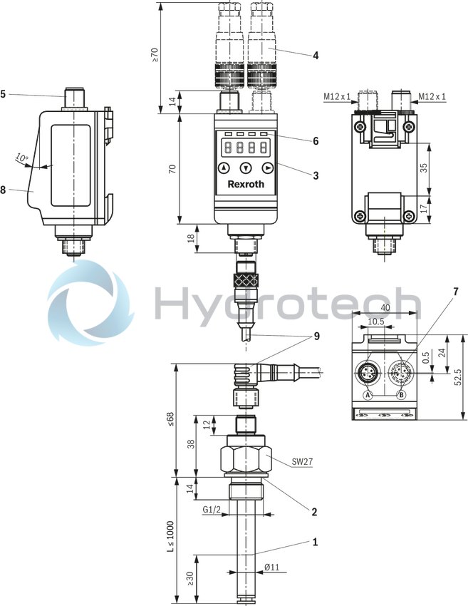
Dimensions: External display and control unit
(version E)Dimensions in mm
|
1 |
Immersion depth at least 30 mm |
|
2 |
Profile seal G1/2 |
|
3 |
Name plate |
|
4 |
Mating connector for plug-in connections K24 (M12 x 1), see table "Mating connector" |
|
5 |
Connector K24; 4-pole M12 x 1 |
|
6 |
LEDs for the display of alarm switching points |
|
7 |
Connector B only with version T4 |
|
8 |
Display and control unit |
|
9 |
Cable set M12 x 1; 4-pole, PUR, see "Ordering code" |
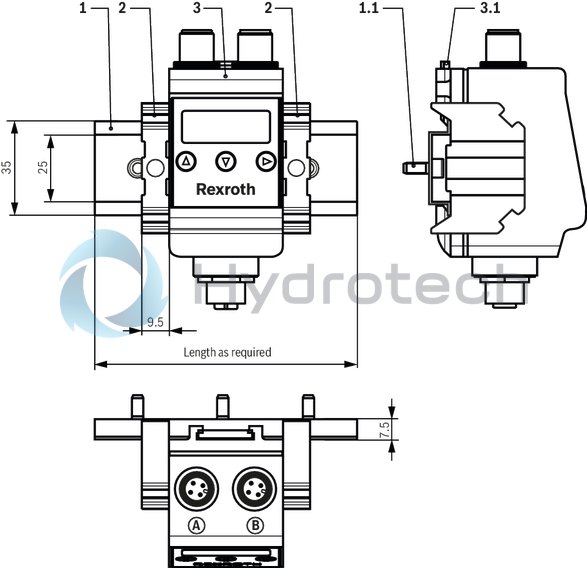
Assembly external display and control unit
|
1 |
Top hat rail TS35 DIN EN 60715 (R900016056) |
|
1.1 |
Hexagon socket head cap screw M5 |
|
2 |
Clamping bracket E/NS35N (R900227399) |
|
3 |
External display and control unit |
|
3.1 |
Mounting clip |
Installation information
Shorten the top hat rail item 1 (supplied length 2000 mm) to the required dimension and fasten it on the substructure using hexagon socket head cap screws M5 item 1.1 Position the display and control unit item 3 on the top hat rail and fast it using the fastening clip item 3.1 Fix the display and control unit item 3 by means of the clamping bracket item 2 on both sidesThe fastening accessories item 1, item 1.1 and item 2 are not included in the scope of delivery of item 3.
Avoid flows Do not expose the switch to heavy impacts and bends Avoid external magnetic fields
Electrical connections:
Electrical connections may only be established by specialists Tighten the round connectors M12 x 1 and/or mating connectors after connection Only plug in the round connectors M12 x 1 and/or mating connectors in the de-energized condition Tightening torque of the screw-in stud 25 Nm In case of inductive load provide a protection circuit!Normative references
R 08006
Mating connectors for controlling electrically operated valves and sensors
DIN 24320
Flame-resistant fluids – Hydraulic fluids of categories HFAE and HFAS – Properties and requirements
DIN 51524
Hydraulic fluids; hydraulic oils
DIN EN 60715
Dimensions of low-voltage switchgear and control gear – Standardized mounting on rails
DIN EN 60751
Industrial platinum resistance thermometers and platinum temperature sensors (IEC 60751:2008)
DIN EN 175201-804:
Detail specification – Circular connectors – Round contacts, size diameter 1.6 mm; threaded coupling; German version EN 175201-804:1999
DIN EN 175301-803:
Detail specification: Rectangular connectors – Flat contacts, 0.8 mm thickness, locking screw not detachable; German version EN 175301-803:1999
DIN EN 60529
Degrees of protection provided by enclosures
VDMA 24317
Fluid technology – Flame-resistant fluids – Technical minimum requirements
VDMA 24568
Fluid technology – Fast biodegradable hydraulic fluids – Technical minimum requirements
VDMA 24574-1
Fluid technology – Terms, menu navigation and electrical connection for fluid sensors
Accessories: (not included in scope of delivery)
Tank installation sleeveMaterial no. R901248320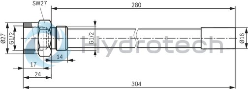
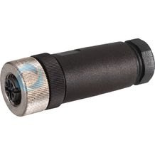
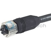
Mating connectors
|
For detailed information see data sheet 08006 |
|||
|
Mating connector for connector K24 |
Mating connector for connector K24 with potted-in PVC cable, 3 m long |
||
|
Denomination |
Part number |
Denomination |
Part number |
|
LEITUNGSDOSE 4P Z24 SPEZ |
R900031155 |
LEITUNGSDOSE 4P Z24M12X1+3MSPEZ |
R900064381 |
Mating connectors for sensors and valves with connector “K24”, “K35” and “K72”, M12 x 1
4P Z24
Mating connectors for sensors and valves with connector “K24”, “K35” and “K72”, M12 x 1
4P Z24
For sensors and valves with connector “K24”, “K35” and “K72” Mating connectors M12, 4-pole, line cross-section 0.75 mm2Data sheet
Spare parts & repair
Mating connectors for sensors and valves with connector “K24”, “K35” and “K72”, M12 x 1, with assembled connection line
4P Z24 +
Mating connectors for sensors and valves with connector “K24”, “K35” and “K72”, M12 x 1, with assembled connection line
4P Z24 +
For sensors and valves with connector “K24”, “K35” and “K72” Mating connectors M12, 4-pole, line cross-section 0.75 mm2Data sheet
Spare parts & repair
Use in explosive areas according to directive 94/9/EC (ATEX)
The electronic contact thermometers according to ABZMT are not suitable for the use in explosive areas.