
BOSCH REXROTH
DBAEE25BF3-2X/315G24K31A1A08
R901253471
Pressure Relief Valves
Pressure valves: DBA* 25.-2x/
BOSCH REXROTH
MATERIAL: R901253471
SUMMARY: Pressure valves: DBA* 25.-2x/
Quantity in stock: 0
General
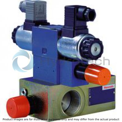
Pump safety blocks type DBAE are pilot-operated pressure relief valves which are integrated into a block and intended to be mounted directly onto SAE pressure ports of pumps.
They are used for limiting and solenoid-actuated unloading (type DBAE.) the operating pressure.
Pump safety block type DBAE(E) for displacement pumps (with proportional pressure relief valve)
In principle, the function corresponds to type DBA....
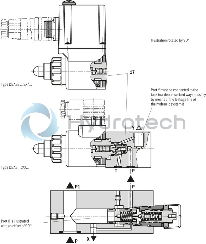
Unloading at the main control spool, however, is achieved by control of the mounted proportional pressure relief valve type DBET(E)-6X/.Y… (17) (data sheet 29162). The cover plate (4) is not required.
The pressure adjustment at the proportional pressure relief valve type DBET(E) only works if it is below the setting of the pressure limitation screw-in cartridge valve type DB 20 K.
Pump safety block type DBAE(E) for variable displacement pumps type A10V.. (with proportional pressure relief valve)
In principle, the function corresponds to type DBA....
By means of the proportional pressure relief valve type DBET(E)-6X/.Y… (17), a pressure change is achieved at the control port X. The pressure change acts on the controller of the pump. The cover plate (4) is not required.
The pressure adjustment at the proportional pressure relief valve type DBET(E) only works if it is below the setting of the pressure limitation screw-in cartridge valve type DB 20 K.
|
01 |
02 |
03 |
04 |
05 |
06 |
07 |
08 |
09 |
10 |
11 |
12 |
13 |
14 |
15 |
16 |
17 |
18 |
19 |
|
|
DBAEE |
B |
2X |
/ |
G24 |
K31 |
|
Type |
||
|
01 |
Pump safety block with mounted proportional pressure relief valve and integrated control electronics, type DBETE-6X/.Y.K31 1) |
DBAEE |
|
Size |
||
|
02 |
Size 16 |
15 |
|
Size 25 |
25 |
|
|
Size 32 |
30 |
|
|
Valve mounting |
||
|
03 |
Without directional valve |
no code |
|
Normally closed |
A |
|
|
Normally open; generally with type DBAE(E) |
B |
|
|
Type of connection / SAE flange 2) |
||
|
04 |
Standard flange (250 … 350 bar) |
F |
|
High-pressure flange (350 bar) |
H |
|
|
Adjustment type for pressure adjustment 3) |
||
|
05 |
Rotary knob |
1 |
|
Sleeve with hexagon and protective cap |
2 |
|
|
Lockable rotary knob with scale |
3 8) |
|
|
Rotary knob with scale |
7 |
|
|
06 |
Without pressure switch |
– |
|
With mounted pressure switch type HED 8 OH… (connector according to DIN EN 175301-803, without mating connector), (data sheet 50061) |
D4) |
|
|
Component series |
||
|
07 |
Component series 20 ... 29 (20 ... 29: unchanged installation and connection dimensions) |
2X |
|
Pressure rating 6) |
||
|
08 |
Set pressure up to 50 bar |
50 |
|
Set pressure up to 100 bar |
100 |
|
|
Set pressure up to 200 bar |
200 |
|
|
Set pressure up to 315 bar |
315 |
|
|
Set pressure up to 350 bar |
350 |
|
|
09 |
Without additional pressure relief valve |
no code |
|
10 |
Standard version |
no code |
|
11 |
Without directional valve |
no code |
|
12 |
Direct voltage 24 V |
G24 |
|
13 |
With concealed manual override (standard) |
N9 9) |
|
With manual override |
N 9) |
|
|
Without manual override |
no code |
|
|
Electrical individual connection 1) |
||
|
14 |
Without mating connector; connector DIN EN 175201-804 |
K31 4) |
|
Interface electronics |
||
|
15 |
Command value 0 … 10 V |
A1 |
|
Command value 4 … 20 mA |
F1 |
|
|
Nozzle fitting |
||
|
16 |
Fixed pumps |
|
|
Lateral channel closed, transverse channel open, pilot oil bore open; (standard for displacement pumps; pure DB-/DBW function) |
no code |
|
|
Variable pumps |
||
|
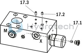
Item 17.1: Lateral channel closed by means of plug, transverse channel open; item 17.2: Pilot oil bore closed by means of plug (e.g. for axial piston variable displacement pump type A4VSO140 with DRG controller) |
A00 |
|
|
Item 17.1: Nozzle Ø0.8 mm in lateral channel, transverse channel open; item 17.2: Pilot oil bore closed by means of plug (standard for control pumps with DFR1 or DFLR controller) |
A08 5) |
|
|
Item 17.1: Nozzle Ø1.0 mm in lateral channel, transverse channel open; item 17.2: Pilot oil bore closed by means of plug (for nozzle fitting of the block, refer to the circuit examples) |
A10 5) |
|
|
Seal material 7) |
||
|
17 |
NBR seals |
no code |
|
FKM seals |
V |
|
|
Type-examination procedure |
||
|
18 |
Without type-examination procedure |
no code |
|
Type-examination tested safety valve according to PED 2014/68/EU |
E |
|
|
19 |
Standard solenoid coil |
no code |
|
Solenoid coil is an approved component with UR-marking according to UL 906 (only version "6E") |
= UR |
|
| 1) Externally discharge the pilot oil from the proportional pressure relief valve type DBETE | |
| 2) Observe the pressure ratings and connection dimensions! | |
| 3) Adjustment type for pressure switch type HED8 in brackets! | |
| 4) Mating connectors, separate order | |
| 5) If used on variable displacement pumps with DFLR controllers, the nozzle at port X of the pump control must be removed! | |
| 6) The same pressure rating at pressure limitation screw-in cartridge valves type DB 20 K, pressure relief valve (sandwich plate valve) type Z(2)DB 6 and pressure switches type HED 8. | |
| 7) Observe compatibility of seals with hydraulic fluid used. (Other seals upon request) | |
| 8) H-key with material no. R900008158 is included in the scope of delivery. | |
| 9) Notice: Accidental activation of the manual override may lead to uncontrolled machine movements. |
Notice! Preferred types and standard units are contained in the EPS (standard price list).
general
|
Size |
16 | 25 | 32 | |||||
|
Mass |
Pump safety block |
kg |
7 | 6.9 | 7 | 7.6 | ||
|
Pressure switches |
HED 8 |
kg |
0.8 | |||||
|
Installation position |
any | |||||||
|
Ambient temperature range |
NBR seals |
°C |
-20 … +50 | - | ||||
|
FKM seals |
°C |
- | -15 … +50 | |||||
hydraulic
|
Size |
16 | 25 | 32 | |||
|
Maximum operating pressure |
Port P |
bar |
350 | |||
|
Maximum counter pressure |
Port Y |
depressurized to the tank | ||||
|
Minimum set pressure |
flow-dependent, see characteristic curves | |||||
|
Maximum set pressure |
bar |
50 100 200 315 350 |
||||
|
Maximum flow |
l/min |
300 | 400 | |||
|
Hydraulic fluid |
see table | |||||
|
Hydraulic fluid temperature range |
NBR seals |
°C |
-20 … +80 | - | ||
|
FKM seals |
°C |
- | -15 … +80 | |||
|
Viscosity range |
mm²/s |
20 … 380 | ||||
|
preferably |
mm²/s |
30 … 46 | ||||
|
Maximum admissible degree of contamination of the hydraulic fluid 1) |
Class 20/18/15 according to ISO 4406 (c) | |||||
| 1) | The cleanliness classes specified for the components must be adhered to in hydraulic systems. Effective filtration prevents faults and simultaneously increases the life cycle of the components. For the selection of the filters, see www.boschrexroth.com/filter. |
|
Hydraulic fluid |
Classification |
Suitable sealing materials |
Standards |
Data sheet |
|
|
Mineral oils |
HL, HLP |
NBR, FKM |
DIN 51524 |
90220 |
|
|
Bio-degradable |
Insoluble in water |
HETG |
NBR, FKM |
ISO 15380 |
90221 |
|
Flame-resistant |
Water-free |
HFDU, HFDR |
FKM |
ISO 12922 |
90222 |
|
Containing water |
HFC (Fuchs Hydrotherm 46M, Petrofer Ultra Safe 620 ) |
NBR |
ISO 12922 |
90223 |
|
Important information on hydraulic fluids:
For further information and data on the use of other hydraulic fluids, please refer to the data sheets above or contact us. There may be limitations regarding the technical valve data (temperature, pressure range, life cycle, maintenance intervals, etc.). The ignition temperature of the hydraulic fluid used must be 40K higher than the maximum surface temperature.Flame-resistant – containing water:
Maximum pressure differential per control edge 50bar Pressure pre-loading at the tank port >20 % of the pressure differential; otherwise, increased cavitation Life cycle as compared to operation with mineral oil HL, HLP 50 … 100 %Bio-degradable and flame-resistant:
If these hydraulic fluids are used, small amounts of dissolved zinc may get into the hydraulic system.Deviating technical data: Type-examination tested safety valves type DBA…E, component series 2X according to Pressure Equipment Directive 2014/68/EU
hydraulic
|
Maximum flow |
See ordering code, safety instructions and characteristic curves "Type-examination tested safety valve" | |
|
Hydraulic fluid |
Mineral oil (HL, HLP) according to DIN 51524-1 and DIN 51524-2 | |
|
Hydraulic fluid temperature range |
°C |
-10 … +60 |
|
Viscosity range |
mm²/s |
12 … 230 |
For applications outside these parameters, please consult us!
(measured with HLP46, ϑOil = 40 ±5 °C)
Inlet pressure dependent on the flow 2)
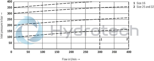
| 1) | The characteristic curves apply to an output pressure pT =0 bar in the entire flow range. |
Notice!
The characteristic curves were measured with internal pilot oil return.
Due to the internal pilot oil return, the inlet pressure increases by the output pressure present in port T.
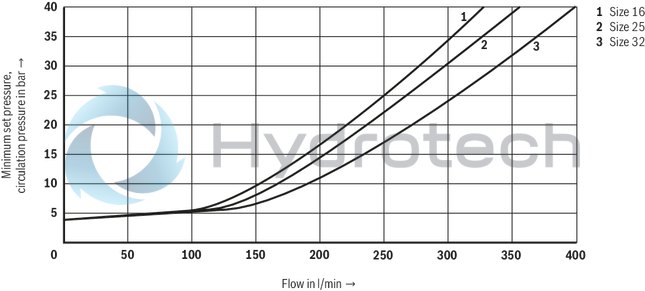
Minimum set pressure and circulation pressure dependent on the flow 1)
Standard version
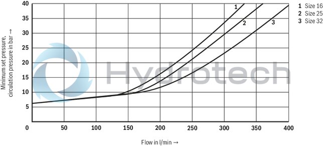
| 1) | The characteristic curves apply to an output pressure pT =0 bar in the entire flow range. |
Minimum set pressure and circulation pressure dependent on the flow 1)
Version “U”
| 1) | The characteristic curves apply to an output pressure pT =0 bar in the entire flow range. |
Safety instructions:Type-examination tested safety valves type DBA…E, component series 2X according to Pressure Equipment Directive 2014/68/EU
Maximum admissible flow q Vmax dependent on the counter pressure pT in the discharge line with internal pilot oil return
Type DBA 15 …-2X/…E
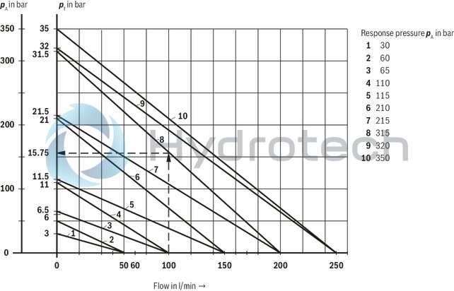
Characteristic curves for intermediate values can be generated by interpolation. Further explanations see below.
|
pA |
Response pressure in bar |
|
pT |
Maximum admissible counter pressure in the discharge line in bar (port T) (sum of all possible counter pressures; also see AD2000 data sheet A2) |
|
pT max |
10 % x pA (with qV = 0) according to PED 2014/68/EU |
|
qV max |
Maximum admissible flow in l/min |
|
Explanation of the diagrams (Example: type DBA 15...E): |
|
|
known: |
Flow of the system/accumulator that has to be secured qVmax = 100 l/min |
|
Set response pressure of the safety valve pA = 315 bar |
|
|
unknown: |
pTadmissible |
|
Solution: |
see arrows in diagram above |
|
pT admissible (100 l/min; 315 bar) = 15.75 bar |
|
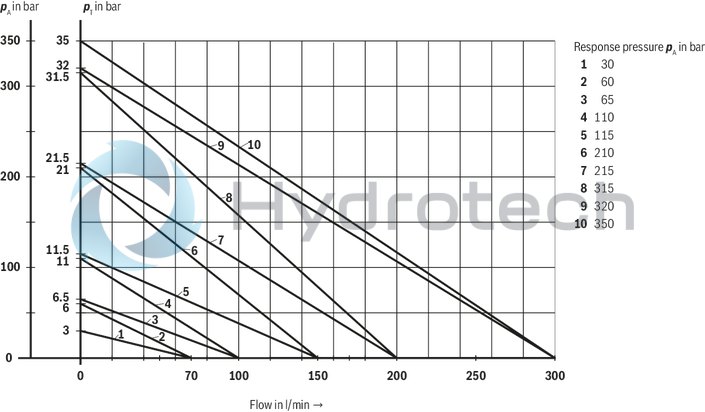
Type DBA 25 …-2X/…E and type DBA 30 …-2X/…E
|
pA |
Response pressure in bar |
|
pT |
Maximum admissible counter pressure in the discharge line in bar (port T) (sum of all possible counter pressures; also see AD2000 data sheet A2) |
|
pT max |
10 % x pA (with qV = 0) according to PED 2014/68/EU |
|
qV max |
Maximum admissible flow in l/min |
General circuit example set-up
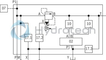
Arrangement of the nozzles/plugs items 17.1, 17.2 and 17.3
Circuit examples: for displacement pumps (selection)
Type DBAE(E)…2X/…
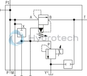
| 1) |
Notice! Port Y of the proportional pressure relief valve type DBET mounted on the pump safety block type DBA must be connected to the tank in a depressurized way (possibly by means of the leakage line of the hydraulic system)! |
Circuit examples: for variable displacement pump (selection)
Preferably for axial piston variable displacement pumps type A10VSO with DR, DFR1 or DFLR controller 2)
Type DBAE(E)…2X/…A08
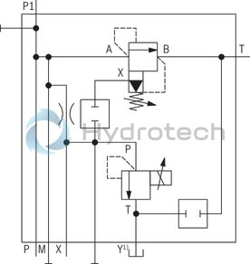
| 1) |
Notice! Port Y of the proportional pressure relief valve type DBET mounted on the pump safety block type DBA must be connected to the tank in a depressurized way (possibly by means of the leakage line of the hydraulic system)! |
| 2) |
Notice! If used on variable displacement pumps with DFLR controllers, the nozzle at port X of the pump control must be removed! |
Preferably for axial piston variable displacement pumps type A10VSO with DRG controller
Type DBAE(E)…2X/…A00
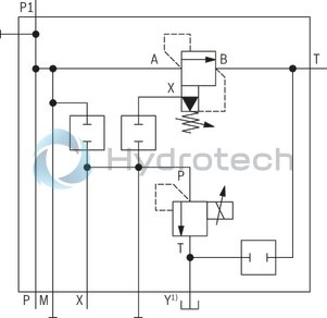
| 1) |
Notice! Port Y of the proportional pressure relief valve type DBET mounted on the pump safety block type DBA must be connected to the tank in a depressurized way (possibly by means of the leakage line of the hydraulic system)! |
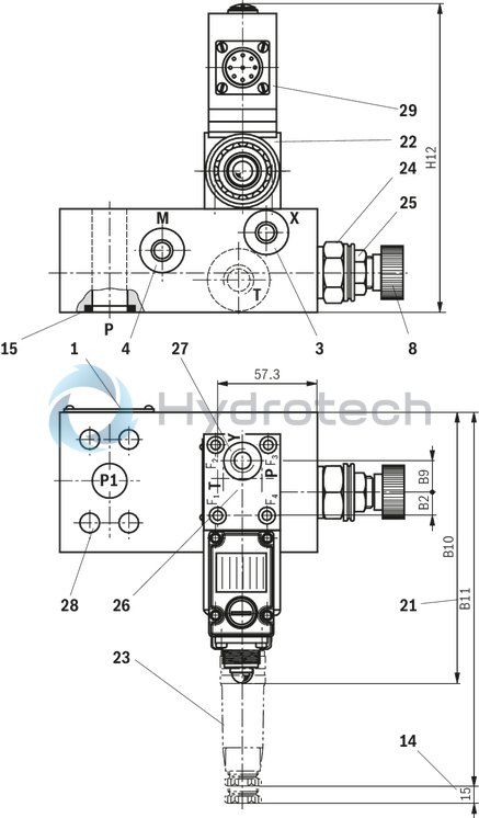
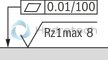
Dimensions in mm
 |
|
Required surface quality of the valve contact surface |
|
1 |
Name plate |
|
3 |
Port X for variable displacement pump type A10VSO (otherwise closed); G1/4 |
|
4 |
Port M for pressure gauge; G1/4 |
|
8 |
Adjustment type "1" |
|
14 |
Space required to remove the mating connector |
|
15 |
Seal ring |
|
21 |
Dimension for valve with integrated electronics |
|
22 |
Proportional pressure relief valve type DBET(E)-6X.Y… (data sheet 29162) |
|
23 |
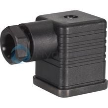
Mating connector for type DBAEE according to DIN EN 175201‑804 (separate order, material no. R90021267) |
|
24 |
Hexagon SW30, tightening torque MA = 50 Nm (For tightening, a manual torque wrench with a tolerance ≤ 10 % must be used.) |
|
25 |
Lock nut SW22, tightening torque MA = 10±5 Nm |
|
26 |
Porting pattern according to DIN 24340 form A (without locating hole), or ISO 4401-03-02-0-05 (with locating hole for locking pin ISO 8752-3x8-St, material no. R900005694, separate order) |
|
27 |
Port Y (G1/4) must be connected to the tank in a depressurized way (possibly by means of the leakage line L of the hydraulic system)! |
|
28 |
Valve mounting bores |
|
29 |
Integrated electronics (OBE) |
Standard flanges type DBAE(E)…F
|
Size |
B2 |
B9 |
B10 |
B11 |
H12 |
|
mm |
mm |
mm |
mm |
mm |
|
| 16 | 12 | 18.8 | 158 | 225 | 175 |
| 25 | 12 | 18.8 | 158 | 225 | 175 |
| 32 | 10 | 20.8 | 158 | 225 | 175 |
High-pressure flanges type DBAE(E)…H
|
Size |
B2 |
B9 |
B10 |
B11 |
H12 |
|
mm |
mm |
mm |
mm |
mm |
|
| 16 | 12 | 18.8 | 158 | 225 | 175 |
| 25 | 12 | 18.8 | 158 | 225 | 175 |
| 32 | 14.5 | 16.3 | 169 | 235 | 179 |
|
Standard flanges type DBA…F… according to DIN ISO 6162-1 |
||||||
|
Size |
Line connections |
4 valve mounting screws ISO 4762 - 10.9 1) |
Tightening torqueMA in Nm 2) |
|||
|
P and P1 |
T |
X, M |
Part number |
|||
|
16 |
SAE 3/4″ |
G3/4 |
G1/4 |
M10 x 95 |
R913015585 |
52 |
|
25 |
SAE 1″ |
G1 |
G1/4 |
M10 x 95 |
R913015585 |
52 |
|
32 |
SAE 1 1/4″ |
G1 1/4 |
G1/4 |
M10 x 95 |
R913015585 |
52 |
|
Admissible pressures (flange connections according to DIN ISO 6121-1) |
|
|
bar |
|
|
SAE 3/4″ |
350 |
|
SAE 1″ |
315 |
|
SAE 1 1/4″ |
250 |
|
High-pressure flanges type DBA…H… according to DIN ISO 6162-2 |
||||||
|
Size |
Line connections |
4 valve mounting screws ISO 4762 - 10.9 1) |
Tightening torqueMA in Nm 2) |
|||
|
P and P1 |
T |
X |
Part number |
|||
|
16 |
SAE 3/4″ |
G3/4 |
G1/4 |
M10 x 95 |
R913015585 |
52 |
|
25 |
SAE 1″ |
G1 |
G1/4 |
M12 x 105 |
R913000659 |
66 |
|
32 |
SAE 1 1/4″ |
G1 1/4 |
G1/4 |
M14 x 105 |
R913000660 |
113 |
|
Admissible pressures (flange connections according to DIN ISO 6121-2) |
|
|
bar |
|
|
SAE 3/4″ |
350 |
|
SAE 1″ |
350 |
|
SAE 1 1/4″ |
350 |
| 1)Valve mounting screws (separate order) | |
| 4 hexagon socket head cap screws ISO 4762 - 10.9-flZn-240h-L | |
| (with friction coefficient μtotal = 0.09 ... 0.14) |
2) Notice!
The tightening torques stated are guidelines when using screws with the specified friction coefficients and when using a manual torque wrench (tolerance ± 10 %).
Notice!
For reasons of stability, other valve mounting screws must not be used!
Depending on the operating pressure, flange height and thread depth of the pump plate, other screw lengths may be necessary!
At types DBAE/DBAEE, the lowest adjustable pressure (circulation pressure) is set at the pressure relief valve in case of power failure or cable break. The unloading function (DBAE/DBAEE) must not be used for safety functions!
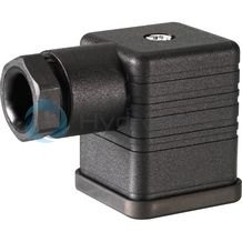
Mating connectors for valves with connector “K4”, without circuitry, standard
3P Z4
Mating connectors for valves with connector “K4”, without circuitry, standard
3P Z4
For valves with connector “K4” according to EN 175301-803 and ISO 4400, 2-pole + PE, “large cubic connector” Mating connectors for valves with one or two solenoids (individual connection)Data sheet
Spare parts & repair
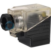
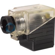
Mating connectors for valves with connector “K4”, with indicator light
3P Z5L
Mating connectors for valves with connector “K4”, with indicator light
3P Z5L
For valves with connector “K4” according to EN 175301-803 and ISO 4400, 2-pole + PE, “large cubic connector” Mating connectors for valves with one or two solenoids (individual connection)Data sheet
Spare parts & repair
Mating connectors for valves with connector “K4”, with indicator light and Zener diode suppression circuit
3P Z5L1
Mating connectors for valves with connector “K4”, with indicator light and Zener diode suppression circuit
3P Z5L1
For valves with connector “K4” according to EN 175301-803 and ISO 4400, 2-pole + PE, “large cubic connector” Mating connectors for valves with one or two solenoids (individual connection)Data sheet
Spare parts & repair
Mating connectors for valves with connector “K4”, with rectifier
3P RZ5
Mating connectors for valves with connector “K4”, with rectifier
3P RZ5
For valves with connector “K4” according to EN 175301-803 and ISO 4400, 2-pole + PE, “large cubic connector” Mating connectors for valves with one or two solenoids (individual connection)Data sheet
Spare parts & repair
Mating connectors for mechanical pressure switches with connector “K14”, without circuitry, standard
4P Z14
Mating connectors for mechanical pressure switches with connector “K14”, without circuitry, standard
4P Z14
For mechanical pressure switches with connector “K14”, according to EN 175301-803 and ISO 4400, 3-pole + PE, “large cubic connector”Data sheet
Spare parts & repair
Mating connectors for mechanical pressure switches with connector “K14”, with indicator lights at connections 2 and 3
4P Z15L
Mating connectors for mechanical pressure switches with connector “K14”, with indicator lights at connections 2 and 3
4P Z15L
For mechanical pressure switches with connector “K14”, according to EN 175301-803 and ISO 4400, 3-pole + PE, “large cubic connector”Data sheet
Spare parts & repair
Ordering code: Type-examination tested safety valves type DBA…E, component series 2X according to Pressure Equipment Directive 2014/68/EU
|
Size |
Type designation |
Component marking |
Maximum admissible flow qVmax in l/min with pilot oil return |
Set response overpressurep in bar |
|
16 |
1 2 3 4 5 6 * 7 DBAEE 15 ▢▢▢▢2X/▢▢6▢▢E |
TÜV.SV.▢‒1001.14,4.F.G.p |
60 100 150 200 250 |
30 … 60 61 … 110 111 … 210 211 … 315 316 … 350 |
|
25 |
1 2 3 4 5 6 * 7 DBAEE 25 ▢▢▢▢2X/▢▢6▢▢E |
TÜV.SV.▢‒1001.14,4.F.G.p |
70 100 150 200 300 |
30 … 60 61 … 110 111 … 210 211 … 315 316 … 350 |
|
32 |
1 2 3 4 5 6 * 7 DBAEE 30 ▢▢▢▢2X/▢▢6▢▢E |
TÜV.SV.▢‒1001.14,4.F.G.p |
70 100 150 200 300 |
30 … 60 61 … 110 111 … 210 211 … 315 316 … 350 |
|
1 |
Directional valve, normally closed |
A |
|
Directional valve, normally open |
B |
|
|
2 |
Standard flange (250 bar) |
F |
|
High-pressure flange (350 bar) |
H |
|
|
3 |
Hand wheel (pressure adjustment sealed, unloading or setting of a lower response pressure possible!) |
1 |
|
With sealed protective cap (no adjustment/unloading possible) |
2 |
|
|
4 |
With mounted pressure switch type HED 8 OH… (without mating connector) |
D |
|
Without pressure switch |
‒ |
|
|
5 |
Pressure in the designation is to be entered by the customer, pressure adjustment ≥ 30 ... 350 bar and possible in 5 bar steps. |
z. B. 150 |
|
2nd/3rd pressure limiting function (see circuit examples) |
||
|
6 |
Without additional pressure relief valve |
no code |
|
With mounted pressure relief valve type ZDB 6 VB…-4X/..SO2 (data sheet 25751) |
Z |
|
|
With mounted pressure relief valve type Z2DB 6 VC…-4X/..SO2 (data sheet 25751) |
ZZ |
|
|
Versions DBAW…Z(Z)E and DBAE(E)…E are only available with ordering code "A00", "A08" or "A10" |
||
|
* |
Ordering code of the electric data |
z. B. EG24N9K4 |
|
7 |
NBR seals |
no code |
|
FKM seals |
V |
|
| Value is entered at the factory! |
Safety instructions: Type-examination tested safety valves type DBA…E, component series 2X according to Pressure Equipment Directive 2014/68/EU
Before ordering a type-examination tested safety valve, it must be observed that for the desired response pressure p, the maximum admissible flow qVmax must be larger than the maximum possible flow of the system to be secured. In this respect, the applicable regulations must be observed! According to PED 2014/68/EU, the increase in the system pressure due to the flow must not exceed 10 % of the set response pressure (see component marking). The maximum admissible flow qVmax stated in the component marking (= numerical value instead of the character "G" in the component marking, see ordering code, type-examination tested safety valves) must not be exceeded. Discharge lines of safety valves must end in a risk-free manner. The accumulation of fluids in the discharge lines must not be possible. If a lead seal at the safety valve is removed, the approval according to the PED! The requirements of the Pressure Equipment Directives 2014/68/EU and of data sheet AD2000 A2 must be generally observed! Options DBAE/DBAEE or 2nd/3rd pressure limiting function ( 6 ) are only possible for pressure relief valves for variable displacement pumps (also see ordering code). The unloading function (DBAE../DBAEE..) must not be used for safety functions! Possible unloading via the directional valve must not be applied for safety-relevant functions! If unloading is required for safety-relevant functions, an additional safety valve must be installed.It is imperative to observe the application notes!
In the plant, the response pressure specified in the component marking is set at a flow of 11 l/min. The maximum admissible flow stated in the component marking applies for applications without counter pressure in the discharge line (port T).Notice!
The system pressure increases by the counter pressure in the discharge line (port T) with increasing flow (observe AD2000 - data sheet A2 - item 6.3!).
To ensure that this increase in system pressure caused by the flow does not exceed the value of 10% of the set response pressure, the admissible flow has to be reduced dependent on the counter pressure in the discharge line (port T) (see diagrams (Safety instructions, Type-examination tested safety valves).