
BOSCH REXROTH
VT-DFPN-A-2X/G24K0/0R0F/V
R901355815
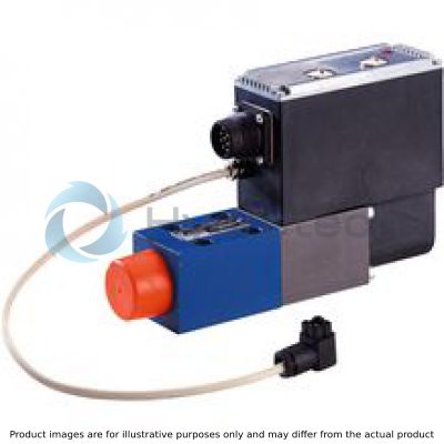
Proportional Directional Valves
VT-DFPn.-2X
BOSCH REXROTH
MATERIAL: R901355815
SUMMARY: VT-DFPn.-2X
Quantity in stock: 0
|
01 |
02 |
03 |
04 |
05 |
06 |
07 |
08 |
09 |
10 |
11 |
||||||
|
VT-DFPn |
- |
- |
2X |
/ |
G24 |
K0 |
/ |
0 |
/ |
- |
* |
|
Series |
|||||||
|
01 |
Pilot valve with integrated digital electronics, variable-speed |
VT-DFPn |
|||||
|
Spool design |
|||||||
|
02 |
Standard (not for HFC fluids) |
A |
|||||
|
2-groove spool (only for replacement requirement) |
B |
||||||
|
4-groove spool (e.g. for HFC fluids) |
C |
||||||
|
03 |
Component series |
2X |
|||||
|
04 |
Direct voltage 24 V |
G24 |
|||||
|
05 |
Connector (without mating connector) 1) |
K0 |
|||||
|
Installation orientation connector (VT-DFP) and/or integrated electronics (see also comment on feature 6) |
|||||||
|
06 |
radially to the pump axis |
0 |
|||||
|
folded 90° in the direction of the subplate with counterclockwise direction of rotation |
1 |
||||||
|
folded 90° in the direction of the subplate with clockwise direction of rotation |
2 |
||||||
|
Additional functions: Closed-loop control |
A |
B |
C |
D |
R |
||
|
07 |
Teach-in version for cyclic operation |
● |
A |
||||
|
Real-time version (speed calculation without teach-in) |
● |
R |
|||||
|
Electronics assembly, option |
|||||||
|
08 |
Standard |
● |
0 |
||||
|
Actual pressure value input |
Plug-in connector |
||||||
|
09 |
Current input 4...20 mA |
X1 |
C |
||||
|
Voltage input 0...10 V (standard) |
X1 |
V |
|||||
|
Voltage input 1...10 V |
X1 |
E |
|||||
|
Voltage input 0.5..5 V (Standard) 2) |
X2 |
F |
|||||
|
10 |
FKM seals suitable for mineral oils (HL, HLP) according to DIN 51524 and HFC fluids 3) |
V |
|||||
|
11 |
Further details in the plain text e. g. SO variant |
* |
|||||
|
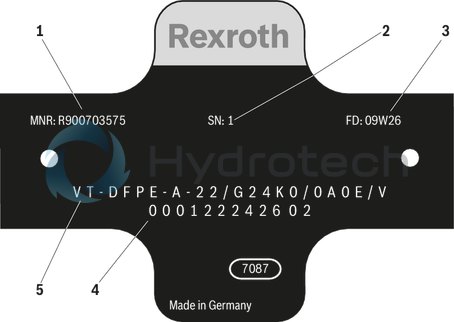
1 |
Material number |
|
2 |
Serial number |
|
3 |
Date of production |
|
4 |
Production order number |
|
5 |
Type designation |
|
● |
available |
|
- |
not available |
Note on feature 6: Installation orientation of the valve electronics
|
Clockwise direction of rotation, installation orientation 0 |
Clockwise direction of rotation, installation orientation 2 |
Counterclockwise direction of rotation, installation orientation 0 |
Counterclockwise direction of rotation, installation orientation 1 |
 |
 |
 |
 |
| 1) | Connector dependent on the valve type (see "Technical data" and "Electrical connection”). |
| 2) | With the SY(H)DFEn control system with analog interfaces, the plug-in connector X2 can not be used as actual pressure value input. Thus, a separate pressure transducer has to be used and connected to plug-in connector X1 in this case. |
| 3) | Only in connection with SYHDFE and spool design C (feature 2). |
|
1 |
Material number |
|
2 |
Serial number |
|
3 |
Date of production |
|
4 |
Production order number |
|
5 |
Type designation |
|
● |
available |
|
- |
not available |
Accessories
Version 10/2011, enquire availability
|
Accessories |
Material number |
Data sheet |
|
Mating connector 12-pole for central connection X1 without cable (assembly kit) |
R900884671 |
08006 |
|
Mating connector 12-pole for central connection X1 with cable set 2 x 5 m |
R900032356 |
|
|
Mating connector 12-pole for central connection X1 with cable set 2 x 20 m |
R900860399 |
|
|
Test device VT-PDFE-1-1X/V0/0 for SY(H)DFEE and SY(H)DFEC |
R900757051 |
29689-B |
|
Compact power supply unit VT-NE32-1X |
R900080049 |
29929 |
|
Converter USB serial for laptops without serial interface VT-ZKO-USB/S-1-1X/V0/0 |
R901066684 |
|
|
Cable for the connection of a Win-PED PC (RS232) at the interface X2, length 3 m |
R901156928 |
|
|
T connector for the simultaneous connection of a WIN-PED PC (RS232) and use of the input at connector X2 |
R901117164 |
|
|
Mating connector for interface X3, M12, straight, can be connected independently, 5-pole, shielded, A coded, cable diameter 6 ... 8 mm |
R901076910 |
Notice:
For information on the environment simulation testing for the areas of EMC (electro-magnetic compatibility), climate and mechanical load, see data sheet 30030-U.
mechanic and hydraulic
|
Mass |
Pump without through-drive incl. pilot valve |
m |
kg |
2.25 |
|
Hydraulic fluid |
Mineral oil (HL, HLP) according to DIN 51524; HFC fluids only in connection with SYHDFE control system and C spool design C (feature 2 of ordering code) | |||
|
Hydraulic fluid temperature range |
ϑ |
°C |
-20 … +70 | |
|
Maximum admissible degree of contamination of the hydraulic fluid according to ISO 4406 |
Class 18/16/13 (for particle size ≤ 4/6/14 μm) | |||
mechanic and hydraulic
|
Weight without filling quantity |
m |
kg |
2.25 |
|
Hydraulic fluid |
Mineral oil (HL, HLP) according to DIN 51524; HFC fluids only in connection with SYHDFE control system and C spool design C (feature 2 of ordering code) | ||
|
Hydraulic fluid temperature range |
ϑ |
°C |
-20 … +70 |
|
Maximum admissible degree of contamination of the hydraulic fluid according to ISO 4406 |
Class 18/16/13 (for particle size ≤ 4/6/14 μm) | ||
electrical
|
Operating voltage |
UB |
24 VDC +40 % –5 % | ||
|
Operating range (short-time operation) |
Upper limit value |
UB(t)max |
V |
35 |
|
Lower limit value |
UB(t)min |
V |
21 | |
|
Current consumption (in static control operation) |
Rated current |
Inom |
A |
0.6 |
|
Maximum current |
Imax |
A |
1.25 | |
|
Inputs |
Actual pressure value input X1; |
U or I |
parameterizable: 0 ... 20 mA; 4 ... 20 mA; 0 ... 10 V; 0 … 5 V; 0.5 … 5 V; 0.1 ... 10 V; 1 ... 10 V | |
|
Analog current inputs, load |
RB |
100 Ω | ||
|
Analog voltage inputs |
RE |
≥ 100 kΩ | ||
|
Digital inputs |
Logic 0 |
≤ 8 V | ||
|
Logic 1 |
≥ 14 V | |||
|
Outputs |
pactual / UOUT1 |
UO 1) |
± 10 V | |
|
Imax 1) |
2 mA | |||
|
αactual / UOUT2 |
UO 1) |
± 10 V | ||
|
Imax 1) |
2 mA | |||
|
Digital outputs |
Logic 0 |
Ua < 1 V | ||
|
Logic 1 |
Ua ≥ UB – 5 V; 10 mA (short-circuit-proof) | |||
|
Ambient temperature range at the pump |
ϑ |
°C |
0 … +50 | |
|
Storage temperature range (pump + electronics) |
ϑ |
°C |
0 … +70 | |
|
Type of protection according to EN 60529 |
Pump incl. pilot valve |
IP65 with mounted and locked plug-in connectors | ||
| 1) | The outputs are parameterizable, for the condition as supplied, see electrical connection |
mechanisch und hydraulisch
|
Weight without filling quantity |
m |
kg |
2.25 |
|
Hydraulic fluid |
Mineral oil (HL, HLP) according to DIN 51524; HFC fluids only in connection with SYHDFE control system and C spool design C (feature 2 of ordering code) | ||
|
Hydraulic fluid temperature range |
ϑ |
°C |
-20 … +70 |
|
Maximum admissible degree of contamination of the hydraulic fluid according to ISO 4406 |
Class 18/16/13 (for particle size ≤ 4/6/14 μm) | ||
elektrisch
|
Operating voltage |
UB |
24 VDC +40 % –5 % | ||
|
Operating range (short-time operation) |
Upper limit value |
UB(t)max |
V |
35 |
|
Lower limit value |
UB(t)min |
V |
21 | |
|
Current consumption (in static control operation) |
Rated current |
Inom |
A |
0.6 |
|
Maximum current |
Imax |
A |
1.25 | |
|
Inputs |
Actual pressure value input X1; |
U or I |
parameterizable: 0 ... 20 mA; 4 ... 20 mA; 0 ... 10 V; 0 … 5 V; 0.5 … 5 V; 0.1 ... 10 V; 1 ... 10 V | |
|
Analog current inputs, load |
RB |
100 Ω | ||
|
Analog voltage inputs |
RE |
≥ 100 kΩ | ||
|
Digital inputs |
Logic 0 |
≤ 8 V | ||
|
Logic 1 |
≥ 14 V | |||
|
Outputs |
nactual / UOUT1 |
UO 1) |
± 10 V | |
|
Imax 1) |
2 mA | |||
|
αactual / UOUT2 |
UO 1) |
± 10 V | ||
|
Imax 1) |
2 mA | |||
|
Digital outputs |
Logic 0 |
Ua < 1 V | ||
|
Logic 1 |
Ua ≥ UB – 5 V; 10 mA (short-circuit-proof) | |||
|
Ambient temperature range at the pump |
ϑ |
°C |
0 … +50 | |
|
Storage temperature range (pump + electronics) |
ϑ |
°C |
0 … +70 | |
|
Type of protection according to EN 60529 |
Pump incl. pilot valve |
IP65 with mounted and locked plug-in connectors | ||
| 1) | The outputs are parameterizable, for the condition as supplied, see electrical connection |
elektrisch
|
Operating voltage |
UB |
24 VDC +40 % –5 % | ||
|
Operating range (short-time operation) |
Upper limit value |
UB(t)max |
V |
35 |
|
Lower limit value |
UB(t)min |
V |
21 | |
|
Current consumption (in static control operation) |
Rated current |
Inom |
A |
0.6 |
|
Maximum current |
Imax |
A |
1.25 | |
|
Inputs |
Actual pressure value input X1; |
U or I |
parameterizable: 0 ... 20 mA; 4 ... 20 mA; 0 ... 10 V; 0 … 5 V; 0.5 … 5 V; 0.1 ... 10 V; 1 ... 10 V | |
|
Analog current inputs, load |
RB |
100 Ω | ||
|
Analog voltage inputs |
RE |
≥ 100 kΩ | ||
|
Digital inputs |
Logic 0 |
≤ 8 V | ||
|
Logic 1 |
≥ 14 V | |||
|
Outputs |
pactual / UOUT1 |
UO |
± 10 V | |
|
Imax |
2 mA | |||
|
αactual / UOUT2 |
UO |
± 10 V | ||
|
Imax |
2 mA | |||
|
Digital outputs |
Logic 0 |
Ua < 1 V | ||
|
Logic 1 |
Ua ≥ UB – 5 V; 10 mA (short-circuit-proof) | |||
|
Ambient temperature range at the pump |
ϑ |
°C |
0 … +50 | |
|
Storage temperature range (pump + electronics) |
ϑ |
°C |
0 … +70 | |
|
Type of protection according to EN 60529 |
Pump incl. pilot valve |
IP65 with mounted and locked plug-in connectors | ||
| 1) | The outputs are parameterizable, for the condition as supplied, see electrical connection |
mechanisch und hydraulisch
|
Mass |
Pump without through-drive incl. pilot valve |
m |
kg |
2.25 |
|
Hydraulic fluid |
Mineral oil (HL, HLP) according to DIN 51524; HFC fluids only in connection with SYHDFE control system and C spool design C (feature 2 of ordering code) | |||
|
Hydraulic fluid temperature range |
ϑ |
°C |
-20 … +70 | |
|
Maximum admissible degree of contamination of the hydraulic fluid according to ISO 4406 |
Class 18/16/13 (for particle size ≤ 4/6/14 μm) | |||
elektrisch
|
Operating voltage |
UB |
24 VDC +40 % –5 % | ||
|
Operating range (short-time operation) |
Upper limit value |
UB(t)max |
V |
35 |
|
Lower limit value |
UB(t)min |
V |
21 | |
|
Current consumption (in static control operation) |
Rated current |
Inom |
A |
0.6 |
|
Maximum current |
Imax |
A |
1.25 | |
|
Inputs |
Actual pressure value input X1; |
U or I |
parameterizable: 0 ... 20 mA; 4 ... 20 mA; 0 ... 10 V; 0 … 5 V; 0.5 … 5 V; 0.1 ... 10 V; 1 ... 10 V | |
|
Analog current inputs, load |
RB |
100 Ω | ||
|
Analog voltage inputs |
RE |
≥ 100 kΩ | ||
|
Digital inputs |
Logic 0 |
≤ 8 V | ||
|
Logic 1 |
≥ 14 V | |||
|
Outputs |
pactual / UOUT1 |
UO |
± 10 V | |
|
Imax |
2 mA | |||
|
αactual / UOUT2 |
UO |
± 10 V | ||
|
Imax |
2 mA | |||
|
Digital outputs |
Logic 0 |
Ua < 1 V | ||
|
Logic 1 |
Ua ≥ UB – 5 V; 10 mA (short-circuit-proof) | |||
|
Ambient temperature range at the pump |
ϑ |
°C |
0 … +50 | |
|
Storage temperature range (pump + electronics) |
ϑ |
°C |
0 … +70 | |
|
Type of protection according to EN 60529 |
Pump incl. pilot valve |
IP65 with mounted and locked plug-in connectors | ||
| 1) | The outputs are parameterizable, for the condition as supplied, see electrical connection |
For applications outside these parameters, please consult us!
With integrated digital electronics
Allocation of connector or mating connector and cable set
X2: Serial interface RS232 and a switchable digital input S1/pressure transducer input for HM 16 (mating connector M12)
|
Pin |
Signal input |
Pin |
Signal RS232 |
|
1 |
OUT, +UB |
2 |
RxD |
|
3 |
Reference L0 |
||
|
4 |
Analog input 0.5...5 V for HM 16 or digital input 0 V low, 10 V high (max. 12 V) |
5 |
TxD |
X3: CAN bus and digital input 2 (connector M12)
|
Pin |
Signal input |
Pin |
Signal CAN |
|
1 |
n.c. |
3 |
CAN GND |
|
2 |
IN, digital IN2 (DI2) |
4 |
CAN-HIGH |
|
5 |
CAN-LOW |
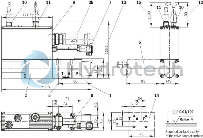
Dimensions in mm
|
1 |
Valve housing |
|
2 |
Proportional solenoid with position transducer |
|
3b |
Mating connector for connector X1 (separate order see Accessories) |
|
5 |
Identical seal rings for ports P, A, and T |
|
6 |
Solenoid rotated by 90° (installation orientation "2") |
|
7 |
Connection swivel angle position sensor (rotary angle sensor VT-SWA-1-1X) |
|
8 |
Name plate |
|
9 |
Integrated electronics |
|
10 |
Mating connector X2 for connection of a pressure transducer HM 16 |
|
11 |
Mating connector X3 for connection of the CAN bus |
|
12 |
Space required for plug-in connection (HM 16) |
|
13 |
Dimension for version VT-DFPC (connection for HM 16 or CAN bus) |
|
14 |
machined valve contact surface |
|
15 |
Space required for CAN connection (plug-in connection on the customer side) |
Valve mounting screws for all types:
4 hexagon socket head cap screws
ISO4762-M6X40-10.9-flZn-240h-L,
friction coefficient μtotal = 0.09 to 0.14 according to VDA 235-101,
Tightening torque MA = 7 Nm,
material number: R913000058
Amending notes on the SY(H)DFE control systems can be found in the operating instructions (see section “Further information about this control system”).