BOSCH REXROTH
DB10-1-5X/200XCV
R901394307
Pressure Relief Valves
Pressure valves: DB* 20.-5x/
BOSCH REXROTH
MATERIAL: R901394307
SUMMARY: Pressure valves: DB* 20.-5x/
Quantity in stock: 0
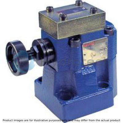
Valves of type DB are pilot-operated pressure limitation valves. They serve to limit the operating pressure and mainly consist of the main valve (1) with main spool insert (3), the pilot control valve (2) and the closing plate (16).
The pressure in channel P acts on the main spool (3).
Simultaneously, the pressure is applied via the control lines (6) and (7), which are equipped with nozzles (4) and (5), to the spring-loaded side of the main spool (3) and to the ball (8) in the pilot control valve (2). If the pressure in channel P is increased due to the value which is set at the spring (9), the ball (8) opens against the spring (9). The signal for this is sent internally via the control lines (10) and (6) from channel P. The hydraulic fluid on the spring-loaded side of the main spool (3) now flows via the control line (7), nozzle bore (11) and ball (8) in the spring chamber (12). From here, it is passed on to the container internally with type DB...–... via control line (13) or externally with type DB...Y... via control line (14). Due to nozzles (4) and (5), there is a pressure drop at the main spool (3). The connection from channel P to channel T is free. Now, the hydraulic fluid flows from channel P to channel T while the set operating pressure is maintained.
Via port "X" (15), the pressure relief valve can be relieved or switched to a different pressure (second pressure rating).
Type DB 10…XC…

See also "General information" in chapter "Technical data".
Notice:
With the attachment of an additional directional spool valve type 3WE 6…, the valve can be extended for solenoid-actuated unloading (see chapter "Project planning information", "Solenoid-actuated unloading").
|
01 |
02 |
03 |
04 |
05 |
06 |
07 |
08 |
09 |
10 |
11 |
|
|
DB |
1 |
5X |
/ |
XC |
V |
|
01 |
Pressure relief valve, pilot controlled |
DB |
|
02 |
Size 10 |
10 |
|
Size 25 |
20 |
|
|
Size 32 |
30 |
|
|
Type of connection |
||
|
03 |
Valve for subplate mounting |
‒ |
|
Valve for threaded connection |
G |
|
|
Adjustment type |
||
|
04 |
Rotary knob |
1 |
|
05 |
with main spool Ø24 mm (NG10, NG25) |
‒ |
|
with main spool Ø28 mm (only with NG32) |
N |
|
|
06 |
Component series 50 … 59 (50 … 59: unchanged installation and connection dimensions) |
5X |
|
07 |
Set pressure up to 50 bar |
50 |
|
Set pressure up to 100 bar |
100 |
|
|
Set pressure up to 200 bar |
200 |
|
|
Set pressure up to 315 bar |
315 |
|
|
Set pressure up to 350 bar |
350 |
|
|
Pilot flow |
||
|
08 |
Pilot oil supply and pilot oil return, internal |
‒ |
|
External pilot oil supply, internal pilot oil return |
X |
|
|
Internal pilot oil supply, external pilot oil return |
Y |
|
|
Pilot oil supply and pilot oil return external |
XY |
|
|
09 |
Standard version |
no code |
|
Valve for minimum cracking pressure (only possible up to pressure rating 315 bar) |
U |
|
|
Explosion protection |
||
|
10 |
Valve in explosion-proof design, for details see information on explosion protection under technical data |
XC |
|
Seal material |
||
|
11 |
FKM seals |
V |
|
Observe compatibility of seals with hydraulic fluid used. |
||
general
|
Size |
10 | 25 | 32 | |||
|
Installation position |
any | |||||
|
Ambient temperature range |
°C |
-20 … +80 | ||||
|
Storage temperature range |
°C |
-20 … +80 | ||||
|
Weight |
Subplate mounting |
DB… |
kg |
2.6 | 3.5 | 4.4 |
|
Threaded connection |
DB…G |
kg |
5.3 | 5.1 | 4.8 | |
|
Surface protection |
Standard: Coating, layer thickness max. 100 μm | |||||
hydraulic
|
Size |
10 | 25 | 32 | ||
|
Maximum operating pressure |
Port P |
bar |
350 | ||
|
Port X |
bar |
350 | |||
|
Port T 1) |
bar |
315 | |||
|
Maximum counter pressure |
Port Y (DB) 1) |
bar |
315 | ||
|
Port Y (with directional spool valve) |
See data sheets from table "The directional spool valve determines the category according to the explosion protection directive 2014/34/EU" in chapter "Project planning information" | ||||
|
Port T (with directional spool valve) |
See data sheets from table "The directional spool valve determines the category according to the explosion protection directive 2014/34/EU" in chapter "Project planning information" | ||||
|
Maximum set pressure 2) |
bar |
50 100 200 315 350 |
|||
|
Minimum set pressure 2) |
flow-dependent, see characteristic curves | ||||
|
Maximum flow |
Subplate mounting |
l/min |
250 | 500 | 650 |
|
Threaded connection |
l/min |
250 | 500 | 650 | |
|
Hydraulic fluid |
see table "Hydraulic fluid" | ||||
|
Hydraulic fluid temperature range |
°C |
-20 … +80 | |||
|
Viscosity range |
mm²/s |
10 … 800 | |||
|
Maximum admissible degree of contamination of the hydraulic fluid 3) |
Class 20/18/15 according to ISO 4406 (c) | ||||
| 1) | Tank preloading is added to set pressure |
| 2) | To avoid exceeding the maximum admissible response pressure, the response pressure must be checked using a suitable measuring device during adjustments. |
| 3) | The cleanliness classes specified for the components must be adhered to in hydraulic systems. Effective filtration prevents faults and simultaneously increases the life cycle of the components. For the selection of the filters, see www.boschrexroth.com/filter. |
|
Hydraulic fluid |
Classification |
Suitable sealing materials |
Standards |
Data sheet |
|
|
Mineral oils |
HL, HLP |
FKM |
DIN 51524 |
90220 |
|
|
Bio-degradable |
Insoluble in water |
HETG |
FKM |
ISO 15380 |
90221 |
|
HEES |
FKM |
||||
|
Soluble in water |
HEPG |
FKM |
ISO 15380 |
||
|
Important information on hydraulic fluids: For further information and data on the use of other hydraulic fluids, please refer to the data sheets above or contact us. There may be limitations regarding the technical valve data (temperature, pressure range, life cycle, maintenance intervals, etc.). The ignition temperature of the hydraulic fluid used must be 50 K higher than the maximum surface temperature. Bio-degradable: Small amounts of dissolved zinc may get into the hydraulic system during use of these hydraulic fluids. |
|||||
General Information
Hydraulic counter pressures in port T with internal pilot oil return and/or port Y with external pilot oil return add 1:1 to the response pressure of the valve set at the pilot control.
Example:
Pressure adjustment of the valve due to spring pretensioning (see chapter "Product description" item 12) in the pilot control valve/adjustment unit: pspring = 200 bar
Hydraulic counter pressure in port T with internal pilot oil return: phydraulic = 50 bar
⇒ Response pressure = pspring + phydraulic = 250 bar
Information on explosion protection
|
Area of application according to directive 2014/34/EU |
IM2, II2G | II2D | |
|
Type of protection valve |
c (EN 13463-5) | ||
|
Maximum surface temperature |
°C |
- | 100 1) |
|
Temperature class |
T4 | - | |
|
Protection class |
- | IP65 | |
| 1) | Due to the surface temperatures of the solenoid coils, the standards ISO 13732-1 and ISO 4413 (contact protection) must be observed. |
(measured with HLP46, ϑOil = 40 ±5 °C)
Standard version
Minimum set pressure and circulation pressure dependent on the flow 1)

| 1) | The characteristic curves apply to an output pressure pT =0 bar in the entire flow range. |
Version “U”
Minimum set pressure and circulation pressure dependent on the flow 1)

| 1) | The characteristic curves apply to an output pressure pT =0 bar in the entire flow range. |
Inlet pressure dependent on the flow

Notice:
The characteristic curves were measured with external, depressurized pilot oil return.
Due to the internal pilot oil return, the inlet pressure increases by the output pressure present in port T.
Pilot flow

Type DB…–…

Type DB…X…

Type DB…Y…

Type DB…XY…

Subplate mounting "–"
Dimensions in mm

 |
|
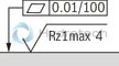
Required surface quality of the valve contact surface |
|
1 |
Name plate |
|
2 |
X port for pilot oil supply, external |
|
3 |
Y port for pilot oil return, external |
|
4 |
Adjustment type "1" |
|
5 |
Locking pin |
|
6 |
Valve mounting bores |
|
7 |
Omitted with internal pilot oil return |
|
8 |
Measuring port |
|
9 |
Lock nut SW17, tightening torque MA = 10+5 Nm |
|
10 |
Lock nut SW17, tightening torque MA = 10+5 Nm |
|
11 |
Cover plate |
|
12 |
Sealing plate |
|
NG |
L1 |
L2 |
L3 |
L4 |
L5 |
L6 |
L7 |
L8 |
L9 |
B1 |
B2 |
ØD1 |
|
mm |
mm |
mm |
mm |
mm |
mm |
mm |
mm |
mm |
mm |
mm |
mm |
|
| 10 | 91 | 53.8 | 22.1 | 27.5 | 22.1 | 47.5 | 0 | 25.5 | 2 | 78 | 53.8 | 14 |
| 25 | 116 | 66.7 | 33.4 | 33.3 | 11.1 | 55.6 | 23.8 | 22.8 | 10.5 | 100 | 70 | 18 |
| 32 | 147.5 | 88.9 | 44.5 | 41 | 12.7 | 76.2 | 31.8 | 20 | 21 | 115 | 82.6 | 20 |
Threaded connection "G"
Dimensions in mm

|
1 |
Name plate |
|
2 |
X port for pilot oil supply, external |
|
3 |
Y port for pilot oil return, external |
|
4 |
Adjustment type "1" |
|
6 |
Valve mounting bores |
|
7 |
Omitted with internal pilot oil return |
|
8 |
Measuring port |
|
9 |
Lock nut SW17, tightening torque MA = 10+5 Nm |
|
10 |
Lock nut SW17, tightening torque MA = 10+5 Nm |
|
11 |
Cover plate |
|
12 |
Sealing plate |
|
NG |
D1 |
ØD2 |
T1 |
|
mm |
mm |
||
| 10 | G1/2 | 34 | 14 |
| 25 | G1 | 47 | 18 |
| 32 | G1 1/2 | 65 | 22 |
Valve mounting screws (subplate mounting) (separate order)
For reasons of stability, exclusively the following valve mounting screws may be used:
NG104 screws ISO 4762 - M12 x 50 - 10.9-flZn/nc/480h/C
friction coefficient μTotal = 0.09 … 0.14
tightening torque MA = 75 Nm ±10 %
material no. R913015611 NG25
4 screws ISO 4762 - M16 x 50 - 10.9-flZn/nc/480h/C
friction coefficient μTotal = 0.09 … 0.14
tightening torque MA = 185 Nm ±10 %
material no. R913015664 NG32
4 screws DIN912 - M18 x 50 - 10.9
tightening torque MA = 248 Nm ±10 %
material no. R900002245
Valve mounting screws (threaded connection)
on request:
2 screwsM10 x … (see dimensions of Threaded connection "G", item 6)
Solenoid-actuated unloading
By mounting a directional spool valve type 3WE 6…, the valve can be modified so that it can be switched to depressurized circulation (main control spool unloaded) by means of electrical control.
Before mounting a directional spool valve 3WE 6… at a pilot-operated pressure relief valve DB…XC, it has to be checked whether the category and protection class resulting from the combination satisfy the requirements of the relevant potentially explosive area.
The directional spool valves suitable for mounting and the resulting categories and protection classes can be seen from the following table.
Important notices:
The unloading function with directional valve must not be used for safety functions. In the assembly, the corresponding operating instructions included in the scope of delivery of the directional spool valves are to be observed. Any mounting and/or modification without operating instructions is not admissible. Before the assembly, all parts are to be identified using the relevant name plates.The directional spool valve determines the category according to the explosion protection directive 2014/34/EU:
|
Directional spool valve |
Category according to 2014/34/EU |
Data sheet |
|
3WE 6…5X/…XH |
II2G |
23177-XH |
|
3WE 6…5X/…XM |
IM2 |
23177-XH |
|
3WE 6…6X/…XD |
IM2; II2G |
23178-XD |
|
3WE 6…6X/…XE |
II2G |
23178-XE |
|
3WE 6…6X/…XN |
II3G; II3D |
23178-XN |
|
Example: |
||
| 1) | Please also observe the possible circuit variations when selecting a valve. |
Example:
Set-up of a directional spool valve 3WE 6…6X/…XE

Notes:
The installation of the directional valve (disassembly of the closing plate) is described in the operating instructions 25802-XC-B.
Circuit variations
For each type of pilot oil supply of a pressure relief valve, two circuit variations for solenoid-actuated unloading are possible:
normally closed normally openThe required circuit variation is determined by the control spool selected for the directional spool valve type 3WE 6...
 |
 |
 |
 |