
BOSCH REXROTH
4WRLE16E1-250LJ-4X/MXY/24A1
R901404333
High-Response Directonal Valves
Control valves: WRL,WRLE* 16.-4x/
BOSCH REXROTH
MATERIAL: R901404333
SUMMARY: Control valves: WRL,WRLE* 16.-4x/
Quantity in stock: 0
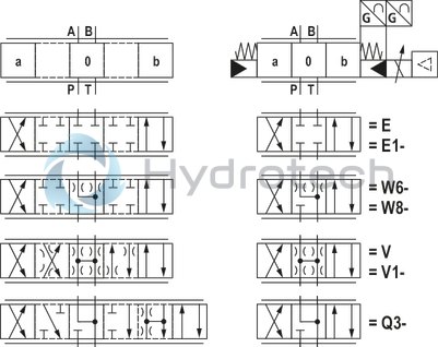
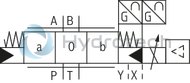
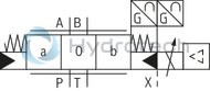
Symbol E. and W.
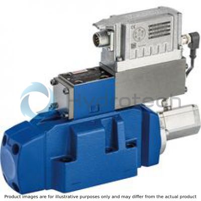
The valve type 4WRLE is a pilot-operated directional control valve with electrical position feedback and on-board electronics (OBE).
Layout
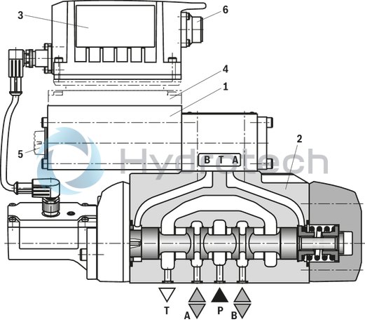
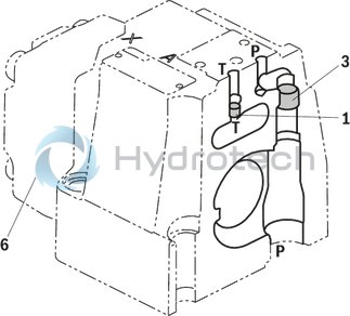
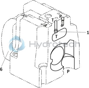
The valve basically consists of 3 main assemblies:
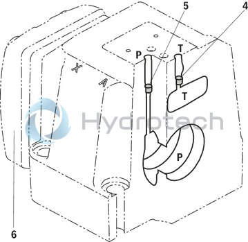
Pilot control valve (1) with control spool and sleeve, return spring, control solenoid and inductive position transducer (optional with electronics protection membrane (5) and damping plate (4)) Main valve (2) with centering spring and position feedback On-board electronics (OBE) (3) with analog or IO-Link interface (6)
Function
When the on-board electronics (OBE) are switched off or inactive, the control spool of the pilot control valve is spring-operated in the "fail-safe" position. The control spool of the main valve is its spring-centered central position.
The on-board electronics (OBE) compare the specified command value to the position actual value of the main valve control spool. In case of control deviations, the control solenoid will be activated. Due to the changed magnetic force, the pilot control spool is adjusted against the spring.
The flow which is activated via the control cross-sections leads to an adjustment of the main control spool. The stroke/control cross-section of the main control spool is regulated proportionally to the command value.
The pilot oil supply in the pilot control valve is either internal via port P or external via port X. The feedback can be internal via port T or external via port Y to the tank.
Control solenoid shut-off
In case of the following errors, the control solenoids are de-energized by the on-board electronics (OBE), the pilot control spool is set to “fail-safe” position and unloads the pilot oil chambers of the main valve. Operated by the spring, the main valve control spool will move to the central position.
Falling below the minimum supply voltage Only with interface "F1": Falling below the minimum current command value of 2 mA (includes cable break of the command value line (current loop)). Only with interface "L1": Enable inactive, communication interruption (watchdog) In case of internal IO-Link error Only with interface "C6": Additionally enable inactive
Damping plate "D"
The damping plate (4) reduces the acceleration amplitudes on the on-board electronics (frequencies >300 Hz).
Notice:
Use of the damping plate is not recommended for applications with mainly low-frequency excitation <300 Hz.
Electronics protection membrane "-967"
To prevent condensate formation in the housing of the on-board electronics (OBE), an electronics protection membrane (5) can be used.
Recommended for use outside industry-standard conditions with high ambient air humidity and significant cyclic temperature changes (e.g. outdoors).
Notice:
Pilot-operated 4/3-directional control valves with positive overlap are functional in controlled or regulated axes. The overlap in the de-energized state is approx. 20% of the control spool stroke. While the electrical supply voltage is switching off, the drive may be accelerated for a short time in functional direction P to B.
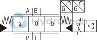
Symbol V and V1-
The valve type 4WRLE is a pilot-operated directional control valve with electrical position feedback and on-board electronics (OBE).
Layout
The valve basically consists of 3 main assemblies:
Pilot control valve (1) with control spool and sleeve, return spring, control solenoid and inductive position transducer (optional with electronics protection membrane (5) and damping plate (4)) Main valve (2) with centering spring and position feedback On-board electronics (OBE) (3) with analog or IO-Link interface (6)
Function
When the on-board electronics (OBE) are switched off or inactive, the control spool of the pilot control valve is spring-operated in the "fail-safe" position. The control spool of the main valve is in its spring-centered offset position at approx. 6% of the stroke in direction P to B/A to T.
The on-board electronics (OBE) compare the specified command value to the position actual value of the main valve control spool. In case of control deviations, the control solenoid will be activated. Due to the changed magnetic force, the pilot control spool is adjusted against the corresponding spring.
The flow which is activated via the control cross-sections leads to an adjustment of the main control spool. The stroke/control cross-section of the main control spool is regulated proportionally to the command value. In case of a command value presetting of 0 V, the electronics adjust the control spool of the main valve to central position.
The pilot oil supply in the pilot control valve is either internal via port P or external via port X. The feedback can be internal via port T or external via port Y to the tank.
Control solenoid shut-off
In case of the following errors, the control solenoids are de-energized by the on-board electronics (OBE), the pilot control spool is set to “fail-safe” position and unloads the pilot oil chambers of the main valve. Operated by the spring, the main valve control spool will move to the offset position (approx. 6% P → B/A → T).
Falling below the minimum supply voltage Only with interface "F1": Falling below the minimum current command value of 2 mA (includes cable break of the command value line (current loop)). Only with interface "L1": Enable inactive, communication interruption (watchdog) In case of internal IO-Link error Only with interface "C6": Additionally enable inactive
Damping plate “D” and electronics protection membrane “-967”
See “symbol E. and W.”:
Notice:
Pilot-operated 4/3 directional control valves are only functional in the active control loop and do not have a locking basic position when deactivated. Consequently "external isolator valves" are required in many applications and must be taken into account regarding the switch-on/switch-off order. While the electrical supply voltage is switching off, the drive may be accelerated for a short time in functional direction P to B.
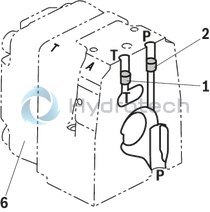
Pilot oil supply (schematic illustration)
Size 10
Size 16
Size 25
Size 27
Size 35
|
1 |
Plug screw M6 according to DIN 906, wrench size 3 - Pilot oil return |
|
2 |
Plug screw M6 according to DIN 906, wrench size 3 - Pilot oil supply |
|
3 |
Plug screw M12x1.5 according to DIN 906, SW6 - Pilot oil supply |
|
4 |
Plug screw 1/16-27 NPTF, wrench size 4 - Pilot oil return |
|
5 |
Plug screw 1/16-27 NPTF, wrench size 4 - Pilot oil supply |
|
6 |
Housing cover main stage (position transducer side) |
|
Pilot oil supply |
|
|
External Internal |
2, 3, 5 closed 2, 3, 5 open |
|
Pilot oil return |
|
|
External Internal |
1, 4 closed 1, 4 open |
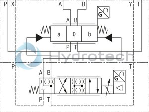
Version “XY"
External pilot oil supply, external pilot oil return
In this version, the pilot oil is supplied from a separate control circuit (external). The pilot oil return is not directed into channel T of the main valve, but is separately directed to the tank via port Y (external).
Version “PY”
Internal pilot oil supply, external pilot oil return
With this version, the pilot oil is supplied from channel P of the main valve (internally). The pilot oil return is not directed into channel T of the main valve, but is separately directed to the tank via port Y (external). In the subplate, port X is to be closed.
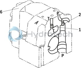
Version “PT”
Internal pilot oil supply; internal pilot oil return
With this version, the pilot oil is supplied from channel P of the main valve (internally). The pilot oil is directly returned to channel T of the main valve (internally). In the subplate, ports X and Y are to be closed.
Version “XT”
External pilot oil supply, internal pilot oil return
In this version, the pilot oil is supplied from a separate control circuit (external). The pilot oil is directly returned to channel T of the main valve (internally). In the subplate, port Y is to be closed.
Notice:
The modification of the pilot oil supply may only be performed by authorized specialists or at the factory. The maximum admissible operating parameters must be observed, see "Technical data".
|
01 |
02 |
03 |
04 |
05 |
06 |
07 |
08 |
09 |
10 |
11 |
12 |
13 |
14 |
15 |
16 |
|||
|
4 |
WRL |
E |
J |
‒ |
4X |
/ |
/ |
24 |
* |
|
01 |
4 main ports |
4 |
|
02 |
High-response directional valve, pilot operated |
WRL |
|
03 |
With integrated electronics (OBE) |
E |
|
04 |
Size 10 |
10 |
|
Size 16 |
16 |
|
|
Size 25 |
25 |
|
|
Size 27 |
27 |
|
|
Size 35 |
35 |
|
|
05 |
Symbols; for the possible version, see "Symbols/Circuit diagrams" |
E, E1-, W6-, W8-, V, V1-, Q3- |
|
Rated flow (Δp = 5 bar) |
||
|
06 |
Size 10 |
|
|
60 l/min (only symbol E, E1-, W6-, W8-, V, V1-) |
60 |
|
|
100 l/min |
100 |
|
|
Size 16 |
||
|
200 l/min (only symbol W6- and W8-) |
200 |
|
|
250 l/min (only symbol E, E1-, V, V1- and Q3-) |
250 |
|
|
Size 25 |
||
|
350 l/min (only symbol W6- and W8-) |
350 |
|
|
400 l/min (only symbol E, E1-, V, V1- and Q3-) |
400 |
|
|
Size 27 |
||
|
430 l/min (only symbol W6- and W8-) |
430 |
|
|
600 l/min (only symbol E, E1-, V, V1- and Q3-) |
600 |
|
|
Size 35 |
||
|
1000 l/min (only symbol E, E1-, V, V1-) |
1000 |
|
|
1200 l/min (only symbol W6- and W8-) |
1200 |
|
|
1500 l/min (only symbol E, E1-, V, V1- and Q3-) |
1500 |
|
|
Flow characteristic |
||
|
07 |
Linear |
L |
|
Linear with fine control range (only NG10; other sizes on request) |
P |
|
|
Progressive with linear fine control (only symbol Q3-) |
M |
|
|
08 |
Overlap jump (opening point 5% with covered valve; only symbols E, E1-, W6-, W8-) |
J |
|
09 |
Component series 40 … 49 (40 … 49: unchanged installation and mounting dimensions) |
4X |
|
Seal material (observe compatibility of seals with hydraulic fluid used, see "Technical data") |
||
|
10 |
NBR seals |
M |
|
FKM seals |
V |
|
|
Pilot oil flow |
||
|
11 |
Pilot oil supply internal, pilot oil return internal |
PT |
|
Internal pilot oil supply, external pilot oil return |
PY |
|
|
External pilot oil supply, internal pilot oil return |
XT |
|
|
External pilot oil supply, external pilot oil return |
XY |
|
|
12 |
Without damping plate |
no code |
|
With damping plate |
D |
|
|
13 |
Supply voltage 24 V |
24 |
|
Interfaces of the control electronics |
||
|
14 |
Command value input ±10 V |
A1 |
|
Command value input 4 … 20 mA |
F1 |
|
|
IO-Link interface |
L1 |
|
|
Command value ±10 mA, actual value 4 ... 20 mA, release (connector 6+PE) |
C6 |
|
|
15 |
Without electronics protection membrane |
no code |
|
With electronics protection membrane |
-967 |
|
|
16 |
Further details in the plain text |
* |
For applications outside these parameters, please consult us!
general
|
Type |
4WRLE | ||||||
|
Size |
10 | 16 | 25 | 27 | 35 | ||
|
Installation position |
Any | ||||||
|
Weight |
kg |
9 | 12 | 19 | 21 | 80 | |
|
Ambient temperature range |
°C |
-20 … +60 | |||||
|
Maximum storage time 1) |
yrs |
1 | |||||
|
Sine test according to DIN EN 60068-2-6 |
Without damping plate |
10 ... 2000 Hz / maximum 10 g / 10 cycles / 3 axes | |||||
|
With damping plate 2) |
10 ... 2000 Hz / maximum 10 g / 10 cycles / 3 axes | ||||||
|
Noise test according to DIN EN 60068-2-64 |
Without damping plate |
20 ... 2000 Hz / 10 gRMS / 30 g peak / 30 min / 3 axes | |||||
|
With damping plate 2) |
20 ... 2000 Hz / 10 gRMS / 30 gpeak/24 h/3 axes | ||||||
|
Transport shock according to DIN EN 60068-2-27 |
Without damping plate |
15 g / 11 ms / 3 shocks / 3 axes | |||||
|
With damping plate 2) |
15 g / 11 ms / 3 shocks / 3 axes | ||||||
|
Shock test according to DIN EN 60068-2-27 |
With damping plate 2) |
35 g / 6 ms / 1000 shocks / 3 axes | |||||
|
Maximum relative humidity 3) |
% |
95 | |||||
|
Maximum solenoid surface temperature 4) |
°C |
120 | |||||
|
MTTFD values according to EN ISO 13849 5) |
Years |
75 | |||||
|
Conformity |
CE according to EMC directive 2014/30/EU tested according EN 61000-6-2 and EN 61000-6-3 RoHS directive 2015/65/EU REACH ordinance (EC) no. 1907/2006 |
||||||
| 1) | If the storage conditions are observed; refer to the operating instructions 07600-B |
| 2) | Not recommended for applications with mainly low-frequency excitation < 300 Hz |
| 3) | No condensation |
| 4) | Individual operation |
| 5) | For further details, see data sheet 08012 |
hydraulic
|
Type |
4WRLE | |||||||
|
Size |
10 | 16 | 25 | 27 | 35 | |||
|
Maximum operating pressure |
Port P |
External pilot oil supply |
bar |
350 | 270 | 350 | ||
|
Anschluss A |
bar |
350 | 270 | 350 | ||||
|
Port B |
bar |
350 | 270 | 350 | ||||
|
Port P |
Internal pilot oil supply |
bar |
280 | 270 | 280 | |||
|
Anschluss A |
bar |
280 | 270 | 280 | ||||
|
Port B |
bar |
280 | 270 | 280 | ||||
|
Port X |
bar |
280 | 270 | 280 | ||||
|
Port Y |
bar |
250 | 210 | 250 | ||||
|
Port T |
bar |
250 | 210 | 250 | ||||
|
Minimum pilot pressure |
Pilot control valve |
bar |
10 | |||||
|
Maximum flow |
l/min |
300 | 800 | 1250 | 1850 | 4700 | ||
|
Nominal flow 1) |
l/min |
60 100 |
200 250 |
350 400 |
430 600 |
1000 1200 1500 |
||
|
Pilot flow 2) |
Symbol E, W |
l/min |
2.4 | 3.5 | 7.5 | 23 | ||
|
Symbol V, Q3- |
l/min |
4.5 | 11.5 | 22 | 29 | |||
|
Maximum leakage flow 3) |
Symbol E, E1- |
Main valve |
l/min |
0.06 | 0.13 | 0.17 | 0.61 | |
|
Main valve + pilot control valve |
l/min |
0.14 | 0.28 | 0.42 | 1.01 | |||
|
Symbol W6-, W8- |
Main valve |
l/min |
0.12 | 0.26 | 0.35 | 1.23 | ||
|
Main valve + pilot control valve |
l/min |
0.2 | 0.41 | 0.61 | 1.63 | |||
|
Symbol V, V1- |
Main valve |
l/min |
1.7 | 2.3 | 2.8 | 3.3 | 7.2 | |
|
Main valve + pilot control valve |
l/min |
1.85 | 2.6 | 3.2 | 3.7 | 7.65 | ||
|
Symbol Q3- |
Main valve |
l/min |
0.4 | 1.6 | 1.8 | 2.2 | 1.6 | |
|
Main valve + pilot control valve |
l/min |
0.55 | 1.9 | 2.2 | 2.6 | 2.05 | ||
|
Flow unloading central position |
Symbol W6; A – T |
l/min |
2.8 | 4 | 6 | 25 | ||
|
Symbol W6; B – T |
l/min |
2.8 | 4 | 6 | 25 | |||
|
Symbol W8; A – T |
l/min |
2.8 | 4 | 6 | 25 | |||
|
Symbol W8; B – T |
l/min |
1.4 | 2 | 3 | 12.5 | |||
|
Pilot volume 0 … 100% |
cm³ |
1.3 | 2.9 | 6.8 | 33.2 | |||
|
Hydraulic fluid |
see table "Hydraulic fluid" | |||||||
|
Hydraulic fluid temperature range 4) |
°C |
-20 … +70 | ||||||
|
Viscosity range |
Maximum admissible |
mm²/s |
10 … 800 | |||||
|
Recommended |
mm²/s |
20 … 100 | ||||||
|
Maximum admissible degree of contamination of the hydraulic fluid, cleanliness class according to ISO 4406 (c) 5) |
Class 18/16/13 | |||||||
| 1) | With Δp = 5 bar/control edge; flow with deviating Δp see formula. |
| 2) | At port X and Y with stepped input signal from 0 to 100 % (pilot pressure 100 bar) |
| 3) | Inlet pressure 100 bar |
| 4) | flown-through |
| 5) | The cleanliness classes specified for the components must be adhered to in hydraulic systems. Effective filtration prevents faults and simultaneously increases the life cycle of the components. For the selection of the filters, see www.boschrexroth.com/filter. |

|
Hydraulic fluid |
Classification |
Suitable sealing materials |
Standards |
Data sheet |
|
|
Mineral oils |
HL, HLP |
NBR, FKM |
DIN 51524 |
90220 |
|
|
Bio-degradable |
Insoluble in water |
HETG |
NBR, FKM |
ISO 15380 |
90221 |
|
HEES |
FKM |
||||
|
Soluble in water |
HEPG |
FKM |
ISO 15380 |
||
|
Flame-resistant |
Water-free |
HFDU (glycol base) |
FKM |
ISO 12922 |
90222 |
|
HFDU (ester base) |
FKM |
||||
|
HFDR |
FKM |
||||
|
Containing water |
HFC (Fuchs: Hydrotherm 46M, Renosafe 500; |
NBR |
ISO 12922 |
90223 |
|
|
Important information on hydraulic fluids: For more information and data on the use of other hydraulicfluids, please refer to the data sheets above or contact us. There may be limitations regarding the technical valve data (temperature, pressure range, life cycle, maintenance intervals, etc.). The ignition temperature of the hydraulic fluid used must be 50 K higher than the maximum surface temperature. Bio-degradable and flame-resistant – containing water: If this hydraulic fluid is used, small amounts of dissolved zinc may get into the hydraulic system. Flame-resistant - containing water: Due to increased cavitation tendency with HFC hydraulic fluids, the life cycle of the component may be reduced by up to 30% as compared to the use with mineral oil HLP. In order to reduce the cavitation effect, it is recommended - if possible specific to the installation - to back up the return flow pressure in ports T to approx. 20% of the pressure differential at the component. Dependent on the hydraulic fluid used, the maximum ambient and hydraulic fluid temperature must not exceed 50 °C. In order to reduce the heat input into the component, the command value profile is to be adjusted for proportional and high-response valves. |
|||||
static / dynamic
|
Type |
4WRLE | |||||||
|
Size |
10 | 16 | 25 | 27 | 35 | |||
|
Hysteresis |
% |
< 0.1 | ||||||
|
Response sensitivity |
% |
< 0.05 | ||||||
|
Range of inversion |
% |
< 0.08 | ||||||
|
Manufacturing tolerance |
% |
≤ 10 | ||||||
|
Switch-off behavior 1) |
Symbol E, E1-, W6-, W8- |
Pilot control valve in “fail-safe” position, main valve moves to spring-centered, overlapped central position | ||||||
|
Symbol V, V1- |
Pilot control valve in “fail-safe” position, main valve moves to spring-centered “offset position” (approx. 6%, P-B/A-T) | |||||||
|
Symbol Q3- |
Pilot control valve in “fail-safe” position, main valve moves to spring-centered "offset position" (P blocked, A/B to port T open) | |||||||
|
Temperature drift 2) |
Zero shift < 0.25 %/10 °C | |||||||
|
Actuating time 3) |
0 ... 100 % |
Symbol E, E1-, W6-, W8- |
ms |
25 | 37 | 36 | 55 | |
|
Zero point calibration 4) |
% |
± 1 | ||||||
| 1) | after electric shut-off |
| 2) | Temperature range 20 °C ... 80 °C |
| 3) | At X = 210 bar |
| 4) | ex works |
electrical, integrated electronics (OBE) – Interface "A1" and "F1"
|
Power supply |
VDC |
24 | |
|
Terminal A |
VDC |
min. 19 / max. 36 | |
|
Terminal B |
VDC |
0 | |
|
Relative duty cycle 1) |
% |
100 | |
|
Protection class according to DIN EN 60529 |
IP65 with mounted and locked plug-in connectors | ||
|
Maximum admissible residual ripple |
Vpp |
2.5 | |
|
Maximum power consumption |
VA |
40 | |
|
Fuse protection, external |
2.5 AT (time-lag) | ||
|
Input, version "A1" |
Differential amplifier, Ri = 100 kΩ | ||
|
Terminal D (UE) |
VDC |
0 … ±10 | |
|
Terminal E |
VDC |
0 | |
|
Input, version "F1" |
Load, Rsh = 200 Ω | ||
|
Terminal D (ID-E) |
mA |
4 … 20 | |
|
Terminal E (ID-E) |
Current loop ID-E return | ||
|
Maximum voltage for the differential inputs compared to 0 V |
D → B; E → B (max. 18 V) | ||
|
Test signal, version "A1" |
LVDT | ||
|
Terminal F (UTest) |
V |
0 … ±10 | |
|
Terminal C |
Reference 0 V | ||
|
Test signal, version "F1" |
LVDT signal 4 … 20 mA on external load 200 … 500 Ω maximum | ||
|
Terminal F (IF-C) |
mA |
4 … 20 | |
|
Terminal C (IF-C) |
Current loop IF-C return | ||
|
Functional earth and screening |
see pin assignment under "Electrical connection" (EMV-compliant installation) | ||
|
Adjustment |
calibrated in the plant, see "characteristic curves" | ||
| 1) | Continuous operation |
electrical, integrated electronics (OBE) – Interface "L1"
|
Power supply |
Valve amplifiers |
VDC |
24 |
|
Pin 2 |
VDC |
min. 18 / max. 30 | |
|
Pin 5 |
VDC |
0 | |
|
IO-Link interface |
VDC |
24 | |
|
Pin 1 |
VDC |
min. 18 / max. 30 | |
|
Pin 3 |
VDC |
0 | |
|
Relative duty cycle 1) |
% |
100 | |
|
Protection class according to DIN EN 60529 |
IP65 with mounted and locked plug-in connectors | ||
|
Maximum current consumption |
Valve amplifiers |
A |
2 |
|
IO-Link interface |
mA |
50 | |
|
Maximum admissible residual ripple |
Vpp |
1.3 | |
|
Minimal process cycle time |
ms |
0.6 | |
|
Bit rate COM3 |
kBit/s |
230.4 | |
|
Required master port class |
Class B | ||
|
Resolution |
A/D transformer |
Bit |
12 (110% valve opening) |
|
D/A transformer |
Bit |
12 (110% valve opening) | |
|
Functional ground |
provide via valve block | ||
|
Adjustment |
calibrated in the plant, see "characteristic curves" | ||
|
Directive |
IO-Link Interface and System Specification Version 1.1.2 | ||
| 1) | Continuous operation |
electrical, integrated electronics (OBE) – Interface "C6"
|
Power supply |
VDC |
24 | |
|
Terminal A |
VDC |
min. 19 / max. 36 | |
|
Terminal B |
VDC |
0 | |
|
Relative duty cycle 1) |
% |
100 | |
|
Protection class according to DIN EN 60529 |
IP65 with mounted and locked plug-in connectors | ||
|
Maximum admissible residual ripple |
Vpp |
2.5 | |
|
Maximum power consumption |
VA |
40 | |
|
Fuse protection, external |
2.5 AT (time-lag) | ||
|
Inlet |
Load, Rsh = 200 Ω | ||
|
Terminal D (ID-E) |
VDC |
0 … ±10 | |
|
Terminal E (ID-E) |
Current loop ID-E return | ||
|
Test signal |
LVDT signal 4 … 20 mA on external load 200 … 500 Ω maximum | ||
|
Terminal F (IF-C) |
mA |
4 … 20 | |
|
Terminal B (IF-C) |
Current loop IF-C return | ||
|
Functional earth and screening |
see pin assignment under "Electrical connection" (EMV-compliant installation) | ||
|
Adjustment |
calibrated in the plant, see "characteristic curves" | ||
| 1) | Continuous operation |
Pressure-signal characteristic curve
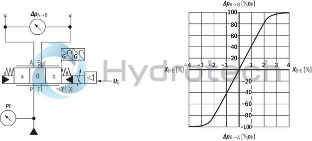
Size 10
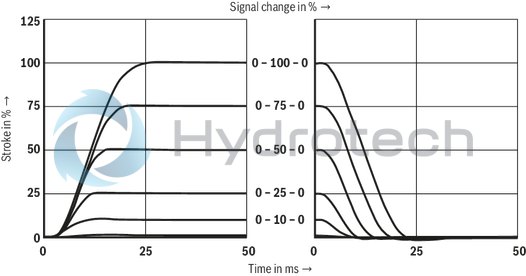
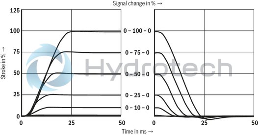
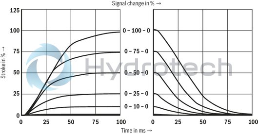
Transition function with stepped electric input signals
Symbols V and Q3-
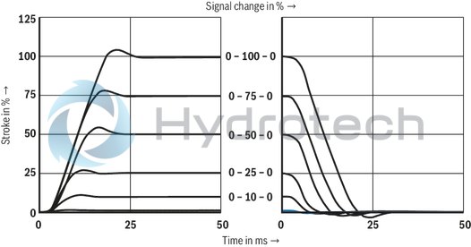 Pilot control valve, port X = 210 bar Main valve, port P = 10 bar
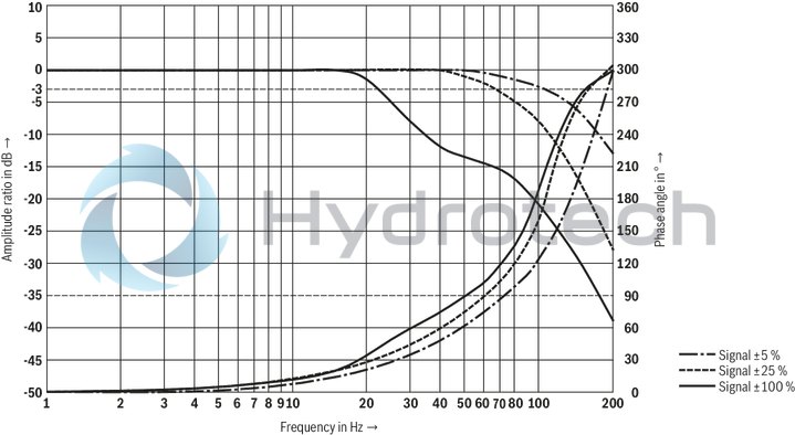
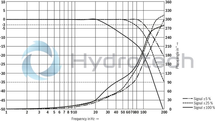
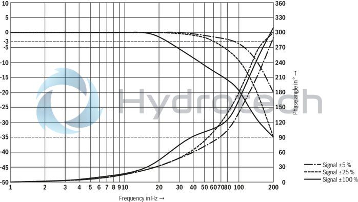
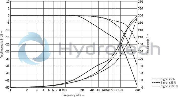
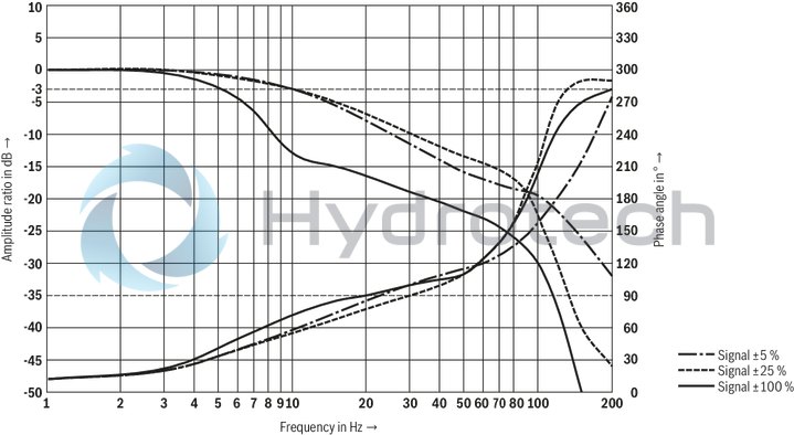
Frequency response
Symbols V and Q3-
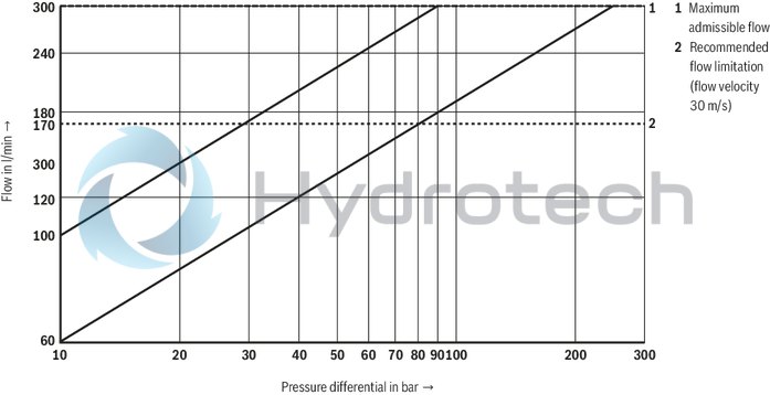
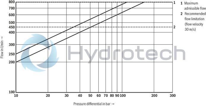
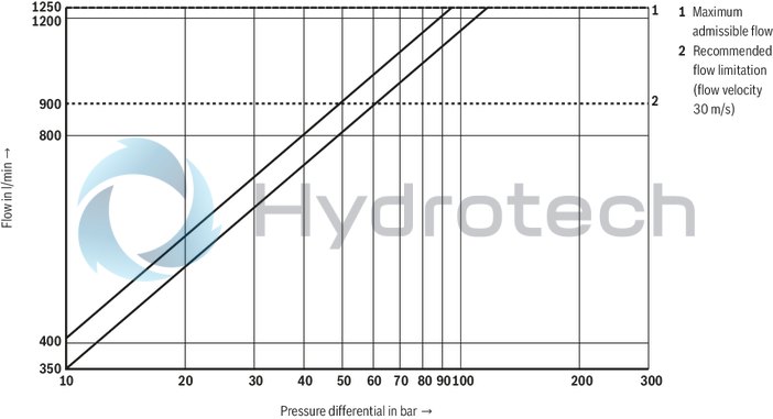
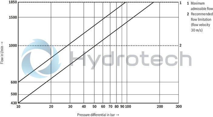
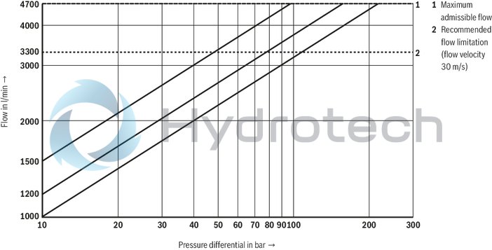
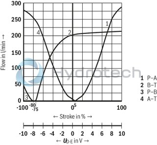
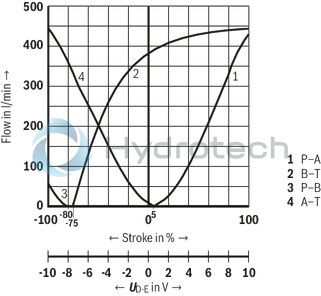
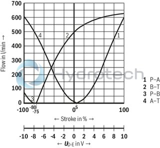
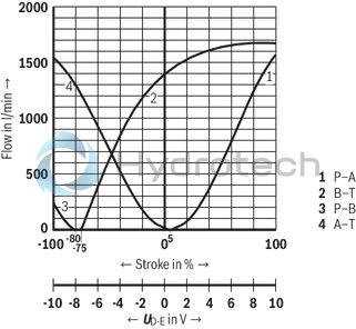
Flow/load function with maximum valve opening (tolerance ±10 %)
Size 16
Transition function with stepped electric input signals
Symbols V and Q3-
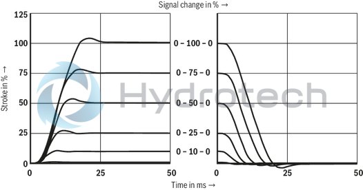 Pilot control valve, port X = 210 bar Main valve, port P = 10 bar
Frequency response
Symbols V and Q3-
Flow/load function with maximum valve opening (tolerance ±10 %)
Size 25
Transition function with stepped electric input signals
Symbols V and Q3-
 Pilot control valve, port X = 210 bar Main valve, port P = 10 bar
Frequency response
Symbols V and Q3-
Flow/load function with maximum valve opening (tolerance ±10 %)
Size 27
Transition function with stepped electric input signals
Symbols V and Q3-
 Pilot control valve, port X = 210 bar Main valve, port P = 10 bar
Frequency response
Symbols V and Q3-
Flow/load function with maximum valve opening (tolerance ±10 %)
Size 35
Transition function with stepped electric input signals
Symbols V and Q3-
 Pilot control valve, port X = 210 bar Main valve, port P = 10 bar
Frequency response
Symbols V and Q3-
Flow/load function with maximum valve opening (tolerance ±10 %)
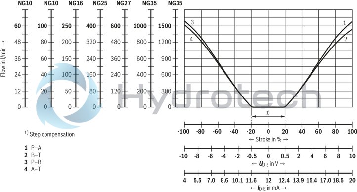
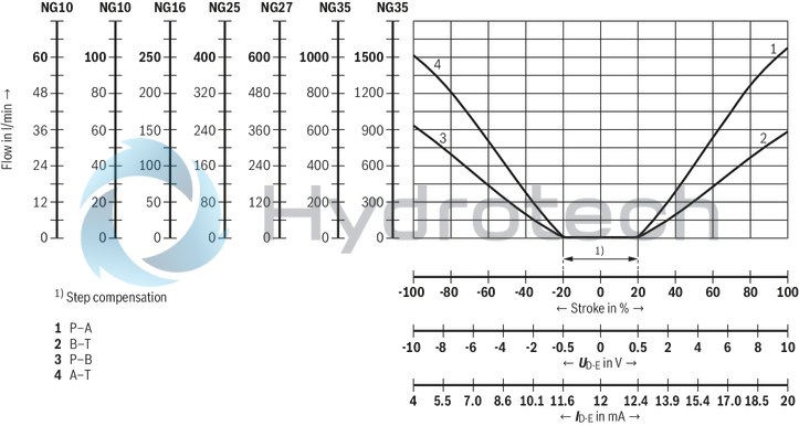
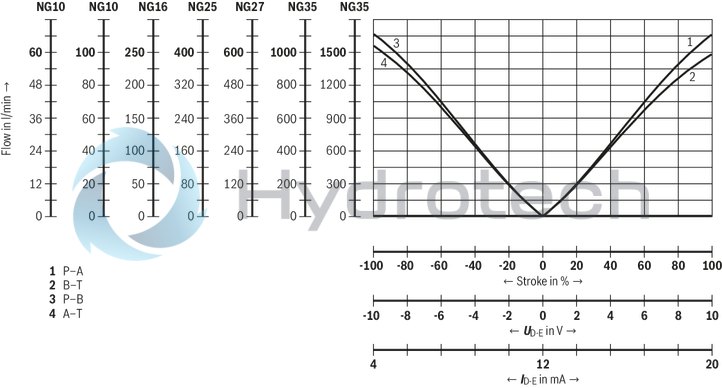
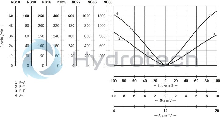
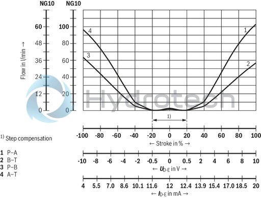
Flow characteristic "L"
(valid for HLP46, ϑOil = 40 ±5 °C; ∆p = 5 bar/control edge)
Flow/signal function
Symbol E
Flow/signal function
Symbol E1-
Flow/signal function
Symbol W6-
Flow/signal function
Symbol W8-
Flow/signal function
Symbol V
Flow/signal function
Symbol V1-
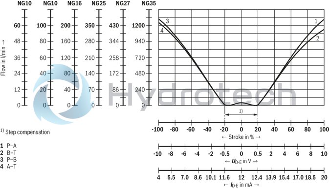
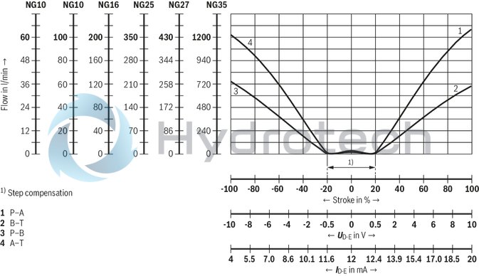
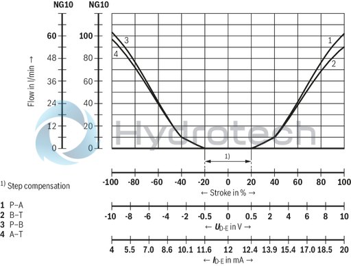
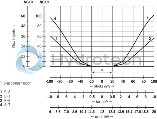
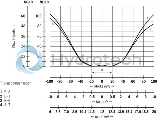
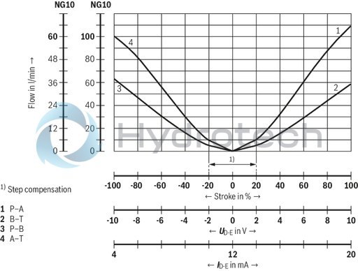
Flow characteristic "P"
(valid for HLP46, ϑOil = 40 ±5 °C; ∆p = 5 bar/control edge)
Flow/signal function
Symbol E
Flow/signal function
Symbol E1-
Flow/signal function
Symbol W6-
Flow/signal function
Symbol W8-
Flow/signal function
Symbol V
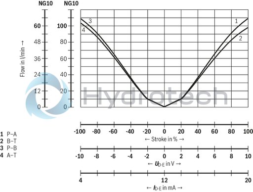
Flow/signal function
Symbol V1-
Flow characteristic "M"
(valid for HLP46, ϑOil = 40 ±5 °C; ∆p = 5 bar/control edge)
Flow/signal function
Symbol Q3, version "100"
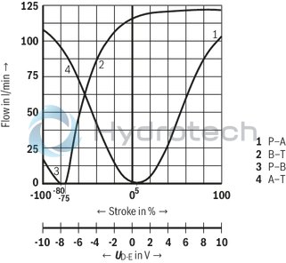
Flow/signal function
Symbol Q3, version "250"
Flow/signal function
Symbol Q3, version "400"
Flow/signal function
Symbol Q3, version "600"
Flow/signal function
Symbol Q3, version "1500"
|
With symbol E1–, V1– and W8–: |
|
|
P → A: qv max |
B → T: qv/2 |
|
P → B: qv/2 |
A → T: qv max |
|
Version |
simple |
Detailed |
|
"XY" |
 |
 |
|
"PY" |
 |
|
|
"PT" |
 |
|
|
"XT" |
 |
Notices:
Representation according to DIN ISO 1219-1. Hydraulic interim positions are shown by dashes. For information on the "switch-off behavior", refer to technical data.Block diagram / controller function block
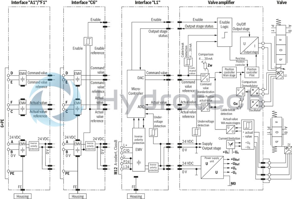
| 1) | Position transducer pilot control valve |
| 2) | Position transducer main valve |
Notices:
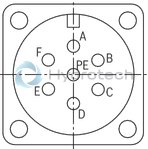
Electrical signals provided via control electronics (e. g. actual value) must not be used for switching off safety-relevant machine functions. The factory setting of the potentiometer must not be changed.Connector pin assignment "A1", "F1" and "C6"
|
Contact |
Interface assignment |
||
|
"A1" (6+PE) |
"F1" (6+PE) |
"C6" (6+PE) |
|
|
A |
24 VDC supply voltage |
||
|
B |
GND |
GND, reference potential actual value/enable |
|
|
C |
Reference potential actual value |
Reference potential actual value/command value; |
|
|
D |
Command value ±10 V |
Command value 4 ... 20 mA |
Command value ±10 mA |
|
E |
Reference potential command value |
||
|
F |
Actual value ±10 V |
Actual value 4 ... 20 mA, load resistance ≈ 330 Ωor digital output (at PLC) 2) |
|
|
PE |
Functional ground (directly connected to valve housing) |
||
Command value:
Positive command value (0 ... 10 V or 12 ... 20 mA) at D and reference potential at E cause flow from P → A and B → T. Negative command value (0 ... -10 V or 12 ... 4 mA) at D and reference potential at E cause flow from P → B and A → T.
Connection cable:
Up to 20 m cable length type LiYCY 7 x 0.75 mm2 Up to 40 m cable length type LiYCY 7 x 1.0 mm2 EMC-compliant installation: Apply screening to both line ends Use metal mating connector (see "Accessories") Alternatively up to 30 m cable length admissible Apply screening on supply side Plastic mating connector (see "Accessories") can be used
Notice:
Mating connectors, separate order, see "Accessories" and data sheet 08006.
Gerätestecker-Belegung „L1“
(M12-5, A-codiert, Class B)
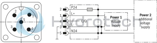
|
Pin |
Signal |
Assignment interface "L1" |
|
1 |
L+ |
Voltage supply IO-Link |
|
2 |
P24 |
Voltage supply valve electronics and power part (current consumption 2 A) |
|
3 |
L- |
Reference potential pin 1 1) |
|
4 |
C/Q |
Data line IO-Link (SDCI) |
|
5 |
N24 |
Reference potential pin 2 1) |
| 1) |
Pin 3 and 5 are linked with each other in the valve electronics. The reference potentials L- and N24 of the two supply voltages must also be linked with each other on the power supply unit side. |
Notices:
M12 sensor/actuator connection line, 5-pole; M12 connector/bush, A-coded, without shield, maximum cable length 20 m. Observe the voltage drop over the cable. Wire cross-section at least 0.34 mm2. Mating connectors, separate order, see "Accessories" and datasheet 08006. Communication and parameter description see data sheet 29400-PASize 10
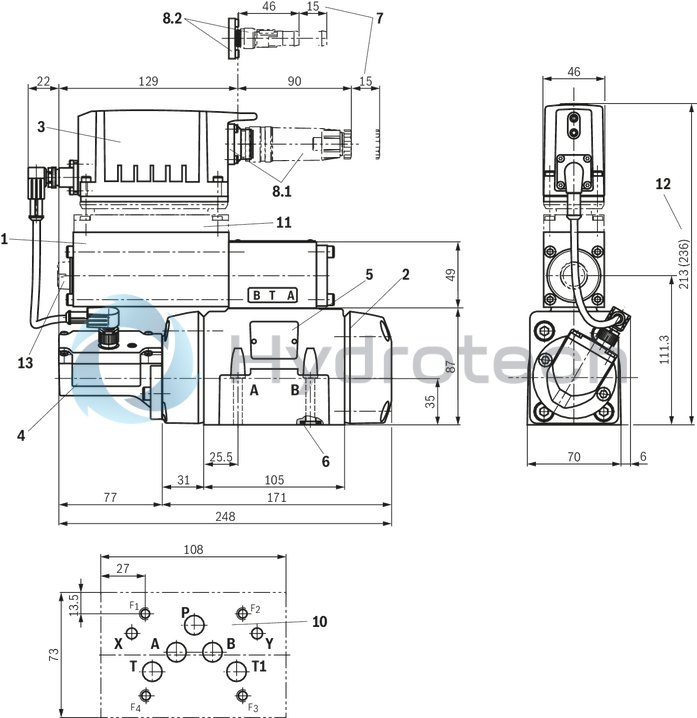
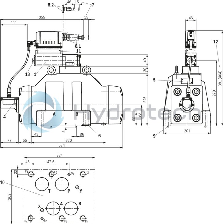
Dimensions in mm
 |
|
Required surface quality of the valve contact surface |
|
1 |
Pilot control valve |
|
2 |
Main valve |
|
3 |
Integrated electronics (OBE) |
|
4 |
Inductive position transducer (main valve) |
|
5 |
Name plate |
|
6 |
Identical seal rings for ports A, B, P, and T Identical seal rings for ports X and Y |
|
7 |
Space required to remove the mating connector |
|
8.1 |
Mating connectors for version "A1", "F1" and "C6", separate order, see "Accessories" and datasheet 08006. |
|
8.2 |
Mating connectors for version "L1", separate order, see "Accessories" and datasheet 08006. |
|
9 |
Locking pin |
|
10 |
Machined valve contact surface; porting pattern according to ISO 4401-05-05-0-05 |
|
11 |
Damping plate "D" |
|
12 |
Dimension in () for version with damping plate "D" |
|
13 |
Electronics protection membrane "-967" |
Notice:
The dimensions are nominal dimensions which are subject to tolerances.
|
Size |
Quantity |
Hexagon socket head cap screws |
Material number |
|
10 |
4 |
ISO 4762 - M6 x 45 - 10.9-CM-Fe-ZnNi-5-Cn-T0-H-B Tightening torque MA = 13.5 Nm ±10 % |
R913043777 |
|
or |
|||
|
4 |
ISO 4762 - M6 x 45 - 10.9 Tightening torque MA = 15.5 Nm ±10 % |
Not included in the Rexroth delivery range |
|
|
or |
|||
|
4 |
ASME B18.3 1/4-20 UNC x 1 3/4“ - ASTM-A574 Tightening torque MA = 15 Nm ±10 % |
Not included in the Rexroth delivery range |
|
Notices:
The tightening torque of the hexagon socket head cap screws refers to the maximum operating pressure. When replacing component series 3X with 4X, only the valve mounting screws listed here may be used. Prior to assembly, check the existing mounting bore on the block for sufficient screw-in depth.Size 16
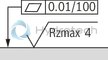
Dimensions in mm
|
|
|
Required surface quality of the valve contact surface |
|
1 |
Pilot control valve |
|
2 |
Main valve |
|
3 |
Integrated electronics (OBE) |
|
4 |
Inductive position transducer (main valve) |
|
5 |
Name plate |
|
6 |
Identical seal rings for ports A, B, P, and T Identical seal rings for ports X and Y |
|
7 |
Space required to remove the mating connector |
|
8.1 |
Mating connectors for version "A1", "F1" and "C6", separate order, see "Accessories" and datasheet 08006. |
|
8.2 |
Mating connectors for version "L1", separate order, see "Accessories" and datasheet 08006. |
|
9 |
Locking pin |
|
10 |
Machined valve contact surface; Porting pattern according to ISO 4401-07-07-0-05 |
|
11 |
Damping plate "D" |
|
12 |
Dimension in () for version with damping plate "D" |
|
14 |
Electronics protection membrane "-967" |
Notice:
The dimensions are nominal dimensions which are subject to tolerances.
|
Size |
Quantity |
Hexagon socket head cap screws |
Material number |
|
16 |
2 |
ISO 4762 - M6 x 60 - 10.9-CM-Fe-ZnNi-5-Cn-T0-H-B Tightening torque MA = 12.5 Nm ±10 % |
R913043410 |
|
4 |
ISO 4762 - M10 x 60 - 10.9-flZn/nc/480h/C Tightening torque MA = 58 Nm ±20 % |
R913014770 |
|
|
or |
|||
|
2 |
ISO 4762 - M6 x 60 - 10.9 Tightening torque MA = 15.5 Nm ±10 % |
Not included in the Rexroth delivery range |
|
|
4 |
ISO 4762 - M10 x 60 - 10.9 Tightening torque MA = 75 Nm ±20 % |
||
|
or |
|||
|
2 |
ASME B18.3 - 1/4-20 UNC x 2 1/4“ - ASTM-A574 Tightening torque MA = 15 Nm ±10 % |
Not included in the Rexroth delivery range |
|
|
4 |
ASME B18.3 - 3/8-16 UNC x 2 1/4“ - ASTM-A574 Tightening torque MA = 60 Nm |
||
Notices:
The tightening torque of the hexagon socket head cap screws refers to the maximum operating pressure. When replacing component series 3X with 4X, only the valve mounting screws listed here may be used. Prior to assembly, check the existing mounting bore on the block for sufficient screw-in depth.Size 25
Dimensions in mm
|
|
|
Required surface quality of the valve contact surface |
|
1 |
Pilot control valve |
|
2 |
Main valve |
|
3 |
Integrated electronics (OBE) |
|
4 |
Inductive position transducer (main valve) |
|
5 |
Name plate |
|
6 |
Identical seal rings for ports A, B, P, and T Identical seal rings for ports X and Y |
|
7 |
Space required to remove the mating connector |
|
8.1 |
Mating connectors for version "A1", "F1" and "C6", separate order, see "Accessories" and datasheet 08006. |
|
8.2 |
Mating connectors for version "L1", separate order, see "Accessories" and datasheet 08006. |
|
9 |
Locking pin |
|
10 |
machined valve contact surface; porting pattern according to ISO 4401-08-08-0-05 |
|
11 |
Damping plate "D" |
|
12 |
Dimension in () for version with damping plate "D" |
|
13 |
Electronics protection membrane "-967" |
Notice:
The dimensions are nominal dimensions which are subject to tolerances.
|
Size |
Quantity |
Hexagon socket head cap screws |
Material number |
|
25, 27 |
6 |
ISO 4762 - M12 x 60 - 10.9-flZn/nc/480h/C Tightening torque MA = 100 Nm ±20 % |
R913015613 |
|
or |
|||
|
6 |
ISO 4762 - M12 x 60 - 10.9 Tightening torque MA = 130 Nm ±20 % |
Not included in the Rexroth delivery range |
|
|
or |
|||
|
6 |
ASME B18.3 - 1/2-13 UNC x 2 1/4“ - ASTM-A574 Tightening torque MA = 110 Nm ±20 % |
Not included in the Rexroth delivery range |
|
Notices:
The tightening torque of the hexagon socket head cap screws refers to the maximum operating pressure. When replacing component series 3X with 4X, only the valve mounting screws listed here may be used. Prior to assembly, check the existing mounting bore on the block for sufficient screw-in depth.Size 27
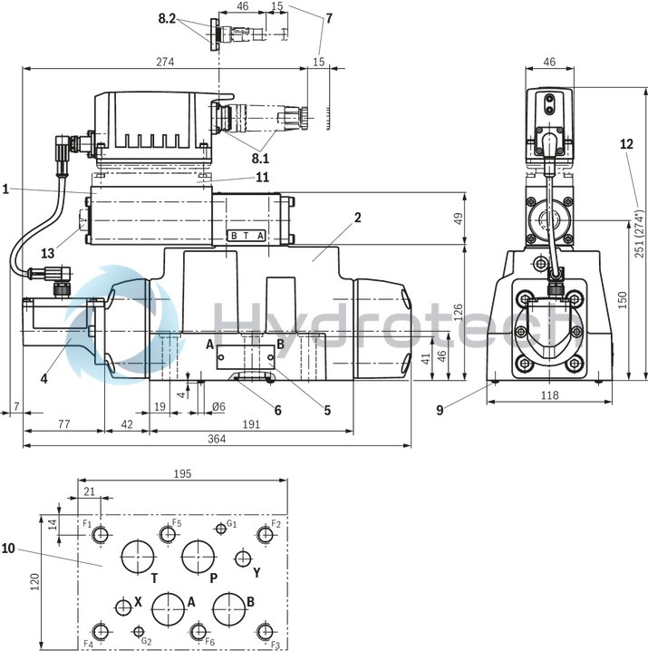
Dimensions in mm

|
|
|
Required surface quality of the valve contact surface |
|
1 |
Pilot control valve |
|
2 |
Main valve |
|
3 |
Integrated electronics (OBE) |
|
4 |
Inductive position transducer (main valve) |
|
5 |
Name plate |
|
6 |
Identical seal rings for ports A, B, P, and T Identical seal rings for ports X and Y |
|
7 |
Space required to remove the mating connector |
|
8.1 |
Mating connectors for version "A1", "F1" and "C6", separate order, see "Accessories" and datasheet 08006. |
|
8.2 |
Mating connectors for version "L1", separate order, see "Accessories" and datasheet 08006. |
|
9 |
Locking pin |
|
10 |
Machined valve contact surface; Porting pattern according to ISO 4401-08-08-0-05 |
|
11 |
Damping plate "D" |
|
12 |
Dimension in () for version with damping plate "D" |
|
13 |
Electronics protection membrane "-967" |
Notice:
The dimensions are nominal dimensions which are subject to tolerances.
|
Size |
Quantity |
Hexagon socket head cap screws |
Material number |
|
25, 27 |
6 |
ISO 4762 - M12 x 60 - 10.9-flZn/nc/480h/C Tightening torque MA = 100 Nm ±20 % |
R913015613 |
|
or |
|||
|
6 |
ISO 4762 - M12 x 60 - 10.9 Tightening torque MA = 130 Nm ±20 % |
Not included in the Rexroth delivery range |
|
|
or |
|||
|
6 |
ASME B18.3 - 1/2-13 UNC x 2 1/4“ - ASTM-A574 Tightening torque MA = 110 Nm ±20 % |
Not included in the Rexroth delivery range |
|
Notices:
The tightening torque of the hexagon socket head cap screws refers to the maximum operating pressure. When replacing component series 3X with 4X, only the valve mounting screws listed here may be used. Prior to assembly, check the existing mounting bore on the block for sufficient screw-in depth.Size 35
Dimensions in mm
|
|
|
Required surface quality of the valve contact surface |
|
1 |
Pilot control valve |
|
2 |
Main valve |
|
3 |
Integrated electronics (OBE) |
|
4 |
Inductive position transducer (main valve) |
|
5 |
Name plate |
|
6 |
Identical seal rings for ports A, B, P, and T Identical seal rings for ports X and Y |
|
7 |
Space required to remove the mating connector |
|
8.1 |
Mating connectors for version "A1", "F1" and "C6", separate order, see "Accessories" and datasheet 08006. |
|
8.2 |
Mating connectors for version "L1", separate order, see "Accessories" and datasheet 08006. |
|
9 |
Locking pin |
|
10 |
Machined valve contact surface; Porting pattern according to ISO 4401-10-09-0-05 |
|
11 |
Damping plate "D" |
|
12 |
Dimension in () for version with damping plate "D" |
|
13 |
Electronics protection membrane "-967" |
Notice:
The dimensions are nominal dimensions which are subject to tolerances.
|
Size |
Quantity |
Hexagon socket head cap screws |
Material number |
|
35 |
6 |
ISO 4762 - M20 x 90 - 10.9-flZn/nc/480h/C Tightening torque MA = 465 Nm ±20 % |
R913009160 |
|
or |
|||
|
6 |
ISO 4762 - M20 x 90 - 10.9 Tightening torque MA = 610 Nm ±20 % |
Not included in the Rexroth delivery range |
|
|
or |
|||
|
6 |
ASME B18.3 - 3/4-10 UNC x 3 1/2“ - ASTM-A574 Tightening torque MA = 395 Nm ±10 % |
Not included in the Rexroth delivery range |
|
Notices:
The tightening torque of the hexagon socket head cap screws refers to the maximum operating pressure. When replacing component series 3X with 4X, only the valve mounting screws listed here may be used. Prior to assembly, check the existing mounting bore on the block for sufficient screw-in depth.Service case with test unit for proportional servo valves with integrated electronics (OBE)
VT-VETSY-1-1X
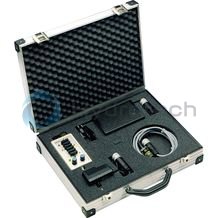
Service case with test unit for proportional servo valves with integrated electronics (OBE)
VT-VETSY-1-1X
Component series 1XData sheet
Configurator / CAD
Spare parts & repair
Mating connectors for valves with round connector, 6-pole + PE
7P Z31
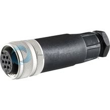
Mating connectors for valves with round connector, 6-pole + PE
7P Z31
For valves with round connector according to EN 175201-804, 6-pole + PE as well as 6-pole, compatible with VG 95328Data sheet
Spare parts & repair
Mating connectors for valves with round connector, 6-pole + PE, shielded, with assembled connection line
7P Z31 +
Mating connectors for valves with round connector, 6-pole + PE, shielded, with assembled connection line
7P Z31 +
For valves with round connector according to EN 175201-804, 6-pole + PE as well as 6-pole, compatible with VG 95328Data sheet
Spare parts & repair