
BOSCH REXROTH
R901413449
$5,366.59 USD
- BOSCH REXROTH
- Material:R901413449
- Model:VT-HPC-1-1X/M-0-00/00
Quantity in stock: 0
The Bosch Rexroth VT-HPC-1-1X/M-0-00/00 (R901413449) is a sophisticated hydraulic pump control module designed specifically for use with the A..HS type axial piston pump. This module is engineered to manage swivel angle, pressure control, and torque limitation functions, ensuring precise operation in various applications. It features digital control electronics that simplify the commissioning process through application-specific functionality and allows for easy parameterization via standard Ethernet connections. The capability for backup and restore operations via an SD card enhances its user-friendliness. With its installation on a DIN rail, this pump control module integrates seamlessly into existing systems. It supports multiple communication protocols including Sercos, PROFINET RT, EtherCAT, EtherNET/IP, and POWERLINK, in addition to analog connectivity options. The unit conforms to CE standards for electromagnetic compatibility within the EU and operates on a supply voltage of 24 VDC. Its modular design is both compact and lightweight. The VT-HPC-1-1X/M-0-00/00 provides a variety of controller functionalities such as pressure control, swivel angle/flow control, torque limitation, and optional speed-variable function integration. It also offers diverse operating modes like pressure/swivel angle control and pressure/flow control. Command value presetting can be achieved through bus interfaces or analog interfaces or by using an internal PLC program. Comprehensive monitoring functions are integrated into the digital controls for error detection including undervoltage issues, communication errors, sensor input cable breaks, short-circuit monitoring for outputs, and temperature monitoring of the electronics. For project planning and parameterization tasks as well as commissioning and diagnostics of this hydraulic pump controller module Bosch Rexroth's IndraWorks PC software can be utilized which requires a PC operating system of at least Windows XP. Lastly, it includes a slot for an SD memory card which enables saving parameter data among other information and allows updates to be made easily provided that the SD card is formatted to FAT with up to 32 Gbyte capacity.
Hydraulic pump control for 1 pump of type A4..HS5, function: Swivel angle, pressure control, torque limitation, master/slave
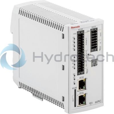
Digital control electronics for the axial piston pump. Reduction of commissioning thanks to application-specific functionality. Parameterizable via standard Ethernet; backup/restore via SD card.
Unpacked Weight: 0.64 kg
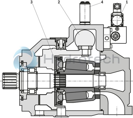
Functional description using the A4VS axial piston pump with HS5 control as an example
The swivel angle and pressure control as well as the torque limitation of the A4VS… variable displacement pump are effected by an electrically controlled proportional valve (1). Via the actuating piston (2) of the pump, this valve determines the position of the swash plate (3).
The position of the swash plate is determined by a swivel angle sensor (4); the actual pressure value is recorded by a pressure transducer.
The actual torque value is calculated from the product of the actual pressure value and the actual swivel angle value. The controller software ensures by means of a minimum value generator that the controller corresponding to the working point is always active.
The sectional drawing shows the A4VS… variable displacement pump with HS5 control; the proportional valve (1) is controlled using the VT-HPC control electronics.
Notice for the HS5 control:
With de-energized proportional valve and pump with clockwise rotation and if the set pressure is available, the pump swivels to swivel angle α = 0 (A4VSO design) or α = –100% (A4VSG design).
Functional description of the control electronics
Description
The VT-HPC (Hydraulic Pump Control) is a digital control system with integrated controller, optionally with programming according to IEC 61131. The internal PLC functionality is activated by plugging the SD card SD-HPC-PLC. It is not included in the VT-HPC scope of delivery and must be ordered separately.
The following controller functionalities are available:
Pressure control Swivel angle/flow control Torque limitation Optional: Speed-variable function (n function)
This enables, amongst others, the following operating modes:
Pressure/swivel angle control Pressure/flow control
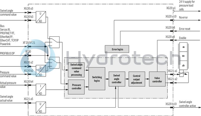
Command value presetting is done via the bus interfaces (XF20/XF21 or XF30), via the analog interface (XG20) or, alternatively, via an internal PLC program.
The feedback information of the actual value signals to the superior control system is provided optionally either via the bus interfaces (XF20/XF21 or XF30) or the analog/digital interface (XG20).
The controller parameters are set via one of the two Ethernet interfaces (XF20/XF21) (integrated switch functionality)
Monitoring
The digital control electronics enable comprehensive monitoring functions/error detection including:
Undervoltage Communication error Cable break for analog sensor inputs (4 ... 20 mA) Short-circuit monitoring for analog/digital outputs Temperature of the integrated electronicsIndraWorks PC program
To implement the project planning task and to parameterize the VT-HPC, the user may use the IndraWorks DS operation tool. For the use of the PLC function, IndraWorks MLD is necessary:
Project planning Parameterization Commissioning Diagnosis Comfortable management of all data on a PC Requirement: PC operating system at least Windows 7
Slot for one SD memory card
The following data may be saved:
Parameter data Any other data Update of the speed-variable function (see Accessories)
Only SD and SDHC memory cards up to a size of 4 Gbyte with FAT32 formatting are supported. The card must already be inserted when the device is switched on, otherwise it will not be detected. It is recommended to use the Rexroth memory card (see Accessories).
| Pump control |
| Installation on DIN rail |
| For 1 pump type A4..HS5 |
| Functionality: Swivel angle, pressure control, torque limitation, master/slave |
| Communication: Sercos, PROFINET RT, EtherCAT, EtherNET/IP, POWERLINK, analog |
| Parameterizable via standard Ethernet |
| Control electronics for the A4VS axial piston pump with HS5 adjustment |
| Component series 1X |
| Communication: Sercos, PROFINET RT, EtherCAT, EtherNET/IP, POWERLINK, optionally PROFIBUS, analog |
| Function: Swivel angle, pressure control, torque limitation, master/slave |
| Data Sheet | Download Data Sheet |
| Manual | Download Manual |
| Manual | Download Manual |
| Manual | Download Manual |
| Manual | Download Manual |
| Manual | Download Manual |
| Productgroup ID | 9,10,11,12,13,14 |
| Conformity description | CE – electromagnetic compatibility 2014/30/EU |
| Supply voltage | 24 VDC |
| Design | Module |
| Weight | 0.64 |
| Connectivity | Bus connection |
| Conformity | CE |
|
01 |
02 |
03 |
04 |
05 |
06 |
|||||
|
VT‒HPC‒1 |
– |
1X |
/ |
M |
– |
– |
00 |
/ |
00 |
|
01 |
Digital control electronics for controlling axial piston variable displacement pumps |
VT-HPC-1 |
|
02 |
Component series 10 ... 19 (10 ... 19: unchanged technical data and pin assignment) |
1X |
|
03 |
Multi-Ethernet |
M |
|
04 |
With Profibus |
P |
|
Without Profibus |
0 |
|
|
05 |
Software option: standard |
00 |
|
06 |
Hardware option: standard |
00 |
Included within the scope of delivery:
Mating connector for
XD1 (Weidmüller BLZF 3.50/03/180F SN BK BX) XG20 (Weidmüller B2CF 3.50/30/180LH SN BK BX) XG21 (Weidmüller B2CF 3.50/14/180LH SN BK BX)For applications outside these parameters, please consult us!
Overview of the controller functions (in the condition as supplied)
Example of open circuit, switch-over between current and voltage interface for the analog inputs via IndraWorks (observe wiring).
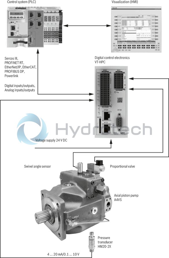
System overview (example)
Pin assignment VT-HPC-1-1X
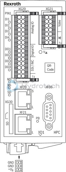
|
XG20, encoder/DIO/AIO |
|||
|
Signal |
Pin |
Pin |
Signal |
|
Do4 1) |
a1 |
b1 |
AGND |
|
Ai1+ |
a2 |
b2 |
Ai1–/Cin1 2) |
|
Ai2+ |
a3 |
b3 |
Ai2–/Cin2 2) |
|
Ai3+ |
a4 |
b4 |
Ai3–/Cin3 2) |
|
Ai4+ |
a5 |
b5 |
Ai4–/Cin4 2) |
|
Ao1 |
a6 |
b6 |
AGND |
|
Ao2 |
a7 |
b7 |
AGND |
|
Di1 |
a8 |
b8 |
Di2 |
|
Di3 |
a9 |
b9 |
Di4 |
|
Do1 1) |
a10 |
b10 |
Do2 1) |
|
reserved |
a11 |
b11 |
reserved |
|
reserved |
a12 |
b12 |
reserved |
|
reserved |
a13 |
b13 |
reserved |
|
reserved |
a14 |
b14 |
GND |
|
Do31) |
a15 |
b15 |
GND |
| 1) | All digital outputs may be used as a voltage supply pin for sensor technology. |
| 2) | Wire current inputs (Cin) for XG20 only at pin b2 … b5, leave pin a2 … a5 open. For XG21, wire pin b7, leave pin a7 open. (See also the information in the operating instructions 30237-B) |
|
XG21 |
|||
|
Signal |
Pin |
Pin |
Signal |
|
Ma+ |
a1 |
b1 |
reserved |
|
Ma- |
a2 |
b2 |
reserved |
|
reserved |
a3 |
b3 |
reserved |
|
reserved |
a4 |
b4 |
reserved |
|
Ai_sv 2) |
a5 |
b5 |
Cin_sv 2) |
|
Vsv |
a6 |
b6 |
GNDsv |
|
Ai5+ |
a7 |
b7 |
Ai5-/Cin5 1) |
| 1) | Wire current inputs (Cin) for XG20 only at pin b2 … b5, leave pin a2 … a5 open. For XG21, wire pin b7, leave pin a7 open. (See also the information in the operating instructions 30237-B) |
| 2) | When connecting swivel angle sensors, you may only connect the relevant required input (Ai_sv for voltage or Cin_sv for current input). The other output must remain open. (in this connection also refer to 30237-B) |
|
XF20, XF21 |
|
|
Ethernet connections |
|
|
Signal |
Pin |
|
TD+ |
1 |
|
TD– |
2 |
|
RD+ |
3 |
|
– |
4 |
|
– |
5 |
|
RD– |
6 |
|
– |
7 |
|
– |
8 |
|
XD1, Power |
|
|
Pin |
Signal |
|
1 |
GND |
|
2 |
GND |
|
3 |
+UB |
|
XF30, PROFIBUS DP (only for P variant) |
|
|
Pin |
Signal |
|
1 |
reserved |
|
2 |
reserved |
|
3 |
RxD/TxD-P |
|
4 |
CNTR-P |
|
5 |
DGND |
|
6 |
VP |
|
7 |
reserved |
|
8 |
RxD/TxD-N |
|
9 |
reserved |
Notice:
The pins marked with "reserved" are reserved and must not be connected!
Dimensions in mm
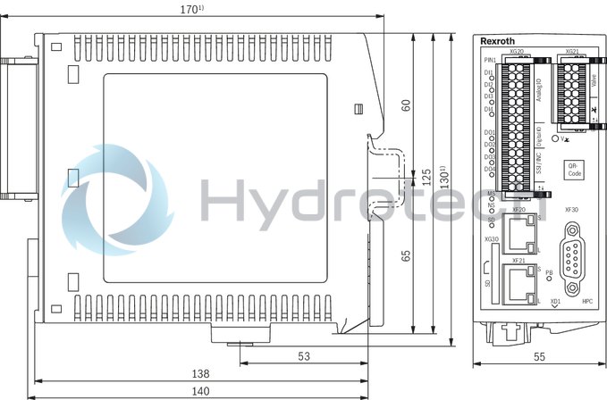
| 1) | Plus 15 mm for connecting/disconnecting the plug-in connector |
Project planning information/maintenance instructions/additional information
Product documentation for VT-HPC:
Data sheet 30237 (this data sheet) Operating instructions 30237-B CE declaration of conformity (available from Bosch Rexroth upon request) Operation of VT-HPC (from firmware version 20V06): Functional description Rexroth HydraulicDrive from HDx-20 Parameter description Rexroth HydraulicDrive from HDx20 RD30330-PA Description of diagnosis Rexroth HydraulicDrive from HDx20 RD3030-WA Library description Rexroth HydraulicDrive, Rexroth IndraMotion MLD (2G), libraries from HDx-20 Additional information Pump control 30237-Z: Notes for commissioning and controller optimization Description of the technology function speed-variable pump control General information on the maintenance and commissioning of hydraulic components: Data sheet 07800/07900Product documentation for base pump A4/HS:
Data sheet RE 92076
Commissioning software and documentation see chapter "Downloads".
Maintenance instructions:
The devices have been tested in the plant and are supplied with default settings. Only complete devices can be repaired. Repaired devices are returned with default settings. User-specific settings will not be applied. The machine end-user will have to retransfer the corresponding user parameters.
Enquiries: support.nc-systems@boschrexroth.de
Notes:
The supply voltage must be permanently connected; otherwise bus communication is not possible. In particularly EMC-sensitive environments, additional measures must be taken (depending on the application, e.g. shielding, filtration) 1) Wiring information Maximum possible separation between signal and load lines. Do not lead signal lines through magnetic fields. If possible, install signal lines without intermediate terminals. Do not install signal lines in parallel to the load lines. Cable shields must be attached on both sides. For digital inputs and outputs, the max. recommended cable length is 30 m. Only use shielded lines for sensors. Max. recommended cable length: 50 m; also observe the sensor manufacturers’ information. Valve lines are to be shielded. Max. recommended cable length: 30 m; also observe the information on the valve. The signals of the connector XG20 and XG21 are not galvanically separated. A potential reference therefore always has to be established when connecting external devices. For additional notes, see IndraWorks online help and operating instructions 30237-B. The upper and lower ventilation slots must not be concealed by adjacent devices in order to provide for sufficient cooling. Observe the installation information in the operating instructions 30237-B
1) To use the HPC for household or small business applications, special precautions, such as installation of a shielded housing and appropriately approved filter systems, are required to fulfill the emission requirements according to EN61000-6-3.
Further information
Notice:
For general information on safety, installation or commissioning, see operating instructions:
07602-B Electronics for industrial applications
Recommended accessories (can be ordered separately)
|
Denomination |
Material number |
|
STECKER 6ES7972-0BA42-0XA0 for port XF30 (Profibus) |
R901312863 |
|
Connection cable PC VT-HPC (RJ45, XF20 or XF21) RKB0011/005.0 length: 5 m |
R911321548 |
|
STECKERSATZ VT-HMC...-1X/M…*ET |
R961011116 |
|
SERVICEPAKET VT-HMC...-1X/M…shielding*ET |
R961011117 |
|
Commissioning software IndraWorks DS from version 14V14 |
- |
|
SD memory card XA-SD01 (1 GByte) |
R911173844 |
|
SD card for PLC functionality VT-SD-HDX-PLC-10VXX |
R901444436 |
|
SD card for n function VT-SD-HPC-HSSN-10VXX |
R901495806 |