
BOSCH REXROTH
R901436311
Electro-Proportional
Throttle valves: WFC* 25.-1x/
BOSCH REXROTH
MATERIAL: R901436311
SUMMARY: Throttle valves: WFC* 25.-1x/
Quantity in stock: 0
Set-up
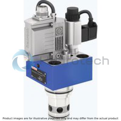
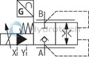
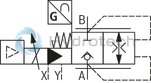
The pilot-operated proportional directional valve type 2WFCE basically consists of:
Cover (1) Main stage (2) Pilot control valve with proportional solenoid (3) Integrated electronics with position transducer and analog interface (4) or external control electronics as module amplifier
The electronics (integrated or external) compare the specified command value to the position actual value of the control spool of the main stage (2). In case of control deviations, the solenoid of the pilot control valve (3) is activated. In this way, the control spool is adjusted. Depending on the control deviation, the control chamber of the main stage (2) is either pressurized with pilot oil (the main stage closes) or unloaded (the main stage opens). Stroke and orifice cross-section are controlled proportionally to the command value until the control deviation is remedied.
For proper function, the following has to be observed:
Direction of flow A → B (X connected to A) Direction of flow B → A (X connected to B) Port Y depressurized to the tank
Failure of supply voltage
If the minimum supply voltage fails or is fallen below, the enable is disconnected (only interfaces B1 and G1) and in case of a cable break of the solenoid conductor, the electronics will de-energize the solenoid of the pilot control valve (3). The control spool of the main stage (2) moves securely to its seat using the pressure available at port X and the force of the main stage spring and blocks the flow between A and B.
Flow control function
In connection with a pressure compensator, the pilot-operated proportional directional valve can be used for the pressure-compensated control of a flow.

|
01 |
02 |
03 |
04 |
05 |
06 |
07 |
08 |
09 |
10 |
11 |
12 |
13 |
|||
|
2 |
WFC |
E |
S |
L |
- |
1X |
/ |
/ |
* |
|
01 |
2 main ports |
2 |
|
02 |
Pilot-operated proportional directional valve (cartridge valve) |
WFC |
|
03 |
With external control electronics |
no code |
|
With integrated electronics (OBE) |
E |
|
|
04 |
Size 16 |
16 |
|
Size 25 |
25 |
|
|
Size 32 |
32 |
|
|
Size 40 |
40 |
|
|
Size 50 |
50 |
|
|
05 |
Seat control spool |
S |
|
Rated flow at 5 bar pressure differential |
||
|
06 |
– Size 16 |
|
|
125 l/min 1) |
125 |
|
|
160 l/min 2) |
160 |
|
|
– Size 25 |
||
|
220 l/min 1) |
220 |
|
|
330 l/min 2) |
330 |
|
|
– Size 32 |
||
|
320 l/min 1) |
320 |
|
|
650 l/min 2) |
650 |
|
|
– Size 40 |
||
|
500 l/min 1) |
500 |
|
|
940 l/min 2) |
940 |
|
|
– Size 50 |
||
|
1000 l/min 1) |
1000 |
|
|
1500 l/min 2) |
1500 |
|
|
Flow characteristic |
||
|
07 |
Linear |
L |
|
08 |
Component series 10 ... 19 (10 ... 19: unchanged installation and connection dimensions) |
1X |
|
Seal material (observe compatibility of seals with hydraulic fluid used, see "Technical data") |
||
|
09 |
NBR seals |
M |
|
FKM seals |
V |
|
|
Electrical connection (With external control electronics) |
||
|
10 |
3-pole connector (2+PE) according to DIN EN 175301-803 |
K4 3) |
|
11 |
Without supply voltage (With external control electronics) |
no code |
|
Supply voltage 24 V (With integrated electronics (OBE) "E") |
24 |
|
|
Electrical interface (With integrated electronics (OBE) "E") |
||
|
12 |
0 ... 10 V DC (connector 6+PE) |
A1 3) |
|
0 ... 10 V DC (connector 11+PE) |
B1 3) |
|
|
4 ... 20 mA (connector 11+PE) |
G1 3) |
|
|
13 |
Further details in the plain text |
* |
| 1) | Control spool Linear (standard) |
| 2) | Control spool Linear–Progressive |
| 3) | Mating connectors, separate order, see "Accessories" |
For applications outside these parameters, please consult us!
general
|
Size |
16 | 25 | 32 | 40 | 50 | ||
|
Weight (approx.) |
"2WFCE" |
kg |
3.5 | 4.6 | 5.8 | 7.9 | 10.5 |
|
"2WFC" |
kg |
3.3 | 4.4 | 5.6 | 7.7 | 10.3 | |
|
Installation position |
Any | ||||||
|
Ambient temperature range |
NBR seals |
°C |
-30 … +60 | ||||
|
FKM seals |
°C |
-20 … +60 | |||||
|
Maximale Lagerzeit |
1 year (if the storage conditions are observed; refer to the operating instructions 07600-B) | ||||||
|
Vibrationsbeständigkeit |
Sine test according to DIN EN 60068-2-6 |
10 ... 2000 Hz / maximum 10 g / 10 cycles / 3 axes | |||||
|
Noise test according to DIN EN 60068-2-64 |
20 ... 2000 Hz / 10 gRMS / 30 g peak / 30 min / 3 axes | ||||||
|
Transport shock according to DIN EN 60068-2-27 |
15 g / 11 ms / 3 axes | ||||||
|
Maximale relative Feuchte (keine Betauung) |
% |
95 | |||||
|
Maximum surface temperature of the coil |
°C |
150 | |||||
|
MTTFD values according to EN ISO 13849 1) |
Years |
75 | |||||
| 1) | For further details, see data sheet 08012 |
hydraulic
|
Size |
16 | 25 | 32 | 40 | 50 | |||
|
Maximum operating pressure |
Anschluss A |
bar |
420 | |||||
|
Port B |
bar |
420 | ||||||
|
Minimaler Betriebsdruck 1) |
Port A (A → B) |
bar |
12 | |||||
|
Port B (B → A) |
bar |
20 | ||||||
|
Maximum pilot pressure |
Port X |
bar |
420 | |||||
|
Maximum return flow pressure |
Port Y |
bar |
100 1) | |||||
|
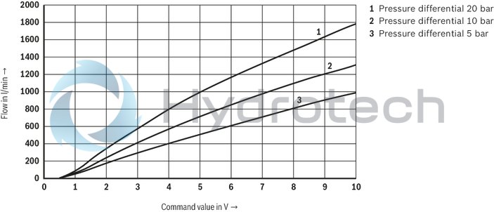
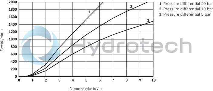
Nominal flow 2) |
Linear |
l/min |
125 | 220 | 320 | 500 | 1000 | |
|
Linear–Progressive |
l/min |
160 | 330 | 650 | 940 | 1500 | ||
|
Maximum pilot flow 3) |
cm³ |
3 | 5 | 7 | 9 | |||
|
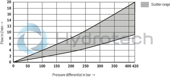
Leakage flow |
Pilot control valve |
at 100 bar |
l/min |
< 0.15 | < 0.2 | < 0.4 | ||
|
Main stage |
Interface A1 (0 V) 4) 5) |
A → B / B → A locked in a leak-free manner (valve in seat position) | ||||||
|
Interface B1 (0 V) |
depending on ∆p, see characteristic curves | |||||||
|
Interface G1 (4 mA) |
depending on ∆p, see characteristic curves | |||||||
|
Interface B1, G1 4) 5) 6) |
A → B / B → A locked in a leak-free manner (valve in seat position) | |||||||
|
Pilot volume 2) |
Main stage |
cm³ |
1 | 2.7 | 6.4 | 12.6 | 24.5 | |
|
Direction of flow 1) |
Internal pilot oil supply |
A → B |
A connected to X | |||||
|
B → A |
B connected to X | |||||||
|
External pilot oil supply |
A → B |
Pressure in X ≥ pressure in A | ||||||
|
B → A |
Pressure in X ≥ pressure in B | |||||||
|
Hydraulic fluid |
see table "Hydraulic fluid" | |||||||
|
Viscosity range |
Recommended |
mm²/s |
20 … 100 | |||||
|
Maximum admissible |
mm²/s |
15 … 380 | ||||||
|
Hydraulic fluid temperature range |
flown-through |
°C |
-20 … +60 | |||||
|
Maximum admissible degree of contamination of the hydraulic fluid, cleanliness class according to ISO 4406 (c) 7) |
Class 18/16/13 | |||||||
| 1) | Counter pressure in port Y; values correspond to Y depressurized to the tank. |
| 2) | With Δp = 5 bar/control edge; flow with deviating Δp see formula. |
| 3) | Stepped input signal (seat position at 100%, pilot pressure 100 bar) |
| 4) | Internal pilot oil supply: Observe leakage flow A → X or B → X via pilot control valve to Y (see technical data leakage flow – pilot control valve) |
| 5) | External pilot oil supply: Leakage flow from A or B via the pilot control valve is avoided; a minimum leakage flow X → B up to 0,03 l/min is, however, possible |
| 6) | Pin 3: 0 V (release not set) |
| 7) | The cleanliness classes specified for the components must be adhered to in hydraulic systems. Effective filtration prevents faults and simultaneously increases the life cycle of the components. For the selection of the filters, see www.boschrexroth.com/filter. |

|
Hydraulic fluid |
Classification |
Suitable sealing materials |
Standards |
Data sheet |
|
|
Mineral oils |
HL, HLP, HLPD, HVLP, HVLPD |
NBR, FKM |
DIN 51524 |
90220 |
|
|
Bio-degradable |
Insoluble in water |
HETG |
FKM |
ISO 15380 |
90221 |
|
HEES |
FKM |
||||
|
Soluble in water |
HEPG |
FKM |
ISO 15380 |
||
|
Flame-resistant |
Water-free |
HFDU (glycol base) |
FKM |
ISO 12922 |
90222 |
|
HFDU (ester base) |
FKM |
||||
|
HFDR |
FKM |
||||
|
Containing water |
HFC (Fuchs Hydrotherm 46M, Fuchs Renosafe 500, Petrofer Ultra Safe 620, Houghton Houghto Safe 620, Union Carbide HP5046) |
NBR |
ISO 12922 |
90223 |
|
|
Important information on hydraulic fluids: For more information and data on the use of other hydraulicfluids, please refer to the data sheets above or contact us. There may be limitations regarding the technical valve data (temperature, pressure range, life cycle, maintenance intervals, etc.). The ignition temperature of the hydraulic fluid used must be 50 K higher than the maximum surface temperature. Bio-degradable and flame-resistant – containing water: If components with galvanic zinc coating (e.g. version "J3" or "J5") or parts containing zinc are used, small amounts of dissolved zinc may get into the hydraulic system and cause accelerated aging of the hydraulic fluid. Zinc soap may form as a chemical reaction product, which may clog filters, nozzles and solenoid valves - particularly in connection with local heat input. Flame-resistant - containing water: Due to increased cavitation tendency with HFC hydraulic fluids, the life cycle of the component may be reduced by up to 30% as compared to the use with mineral oil HLP. In order to reduce the cavitation effect, it is recommended - if possible specific to the installation - to back up the return flow pressure in ports T to approx. 20% of the pressure differential at the component. Dependent on the hydraulic fluid used, the maximum ambient and hydraulic fluid temperature must not exceed 50 °C. In order to reduce the heat input into the component, the command value profile is to be adjusted for proportional and high-response valves. |
|||||
static / dynamic
|
Size |
16 | 25 | 32 | 40 | 50 | |
|
Hysteresis |
% |
< 0.2 | ||||
|
Range of inversion |
% |
< 0.1 | ||||
|
Response sensitivity |
% |
< 0.1 | ||||
|
Manufacturing tolerance 1) |
% |
≤ 10 | ||||
|
Temperature drift |
%/40 K |
< 1 | ||||
|
Zero compensation 2) |
% |
± 1 | ||||
| 1) | qVmax (control spool Linear) |
| 2) | ex works |
electrical, integrated electronics (OBE)
|
Size |
16 | 25 | 32 | 40 | 50 | ||
|
Relative duty cycle 1) |
% |
100 | |||||
|
Protection class according to EN 60529 |
IP65 (If a suitable and a correctly mounted mating connector are used.) | ||||||
|
Power supply |
Nominal voltage |
V DC |
24 | ||||
|
Lower limit value |
V DC |
18 | |||||
|
Upper limit value |
V DC |
36 | |||||
|
Maximum admissible residual ripple 2) |
Vpp |
2.5 | |||||
|
Current consumption |
Maximum |
A |
2 | ||||
|
Impulse current |
A |
3 | |||||
|
Maximum power consumption |
W |
50 | |||||
|
Functional earth and screening |
see connector pin assignment (CE-compliant installation) | ||||||
|
Required fuse protection |
External |
2.5 A time-lag | |||||
|
Adjustment |
calibrated in the plant, see "characteristic curves" | ||||||
|
Conformity |
- CE according to EMC directive 2014/30/EU, tested according to EN 61000-6-2 and EN 61000-6-3 - RoHS directive 2015/65/EU - REACH ordinance (EC) no. 1907/2006 |
||||||
| 1) | Continuous operation |
| 2) | Observe the absolute limit values of the supply voltage. |
(measured with HLP46, ϑOil = 40 ±5 °C)
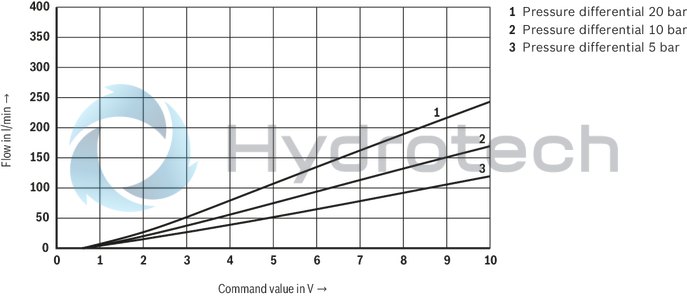
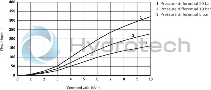
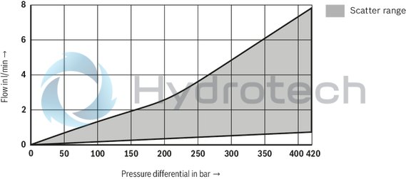
Size 16
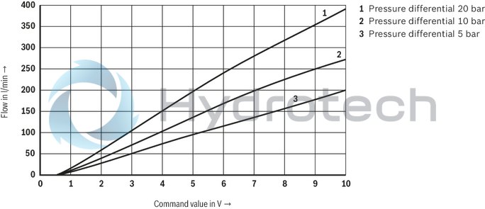
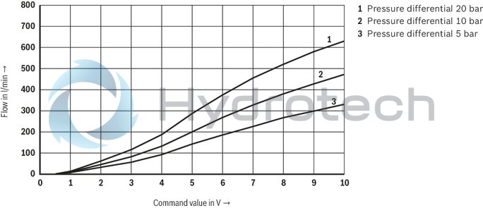
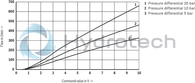
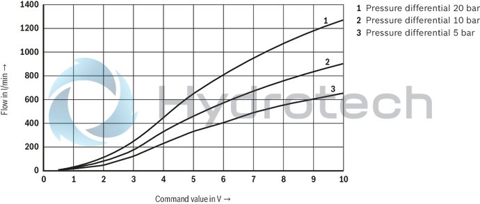
Flow/signal function
Version "125" (A → B; B → A; linear)
Flow/signal function
Version "160" (A → B; B → A; linear-progressive)
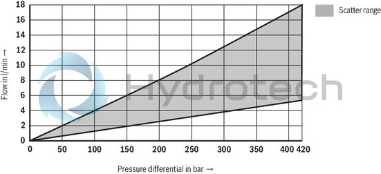
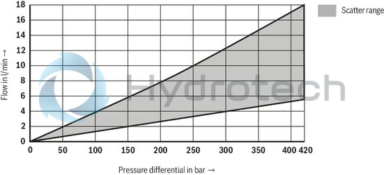
Leakage as a function of the pressure differential
(Command value: A1 – 0.5 V; B1 – 0 V; G1 – 4 mA)
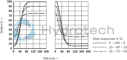
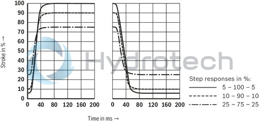
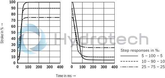
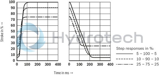
Transition function with stepped electric input signals
(pA = pB = 100 bar; port B closed)
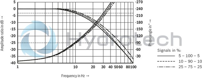
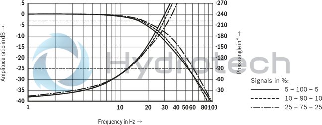
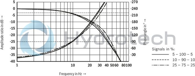
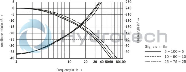
Frequency response
(pA = 100 bar)
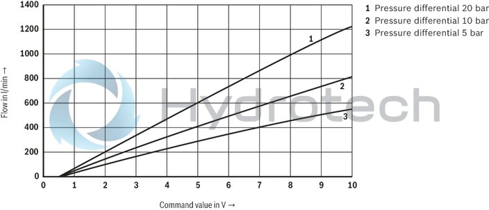
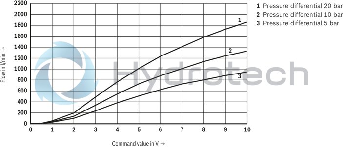
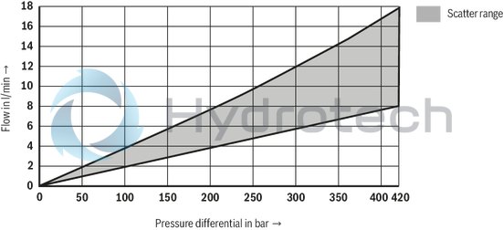
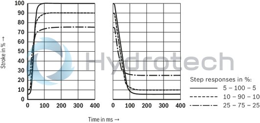
Size 25
Flow/signal function
Version "220" (A → B; B → A; linear)
Flow/signal function
Version "330" (A → B; B → A; linear-progressive)
Leakage as a function of the pressure differential
(Command value: A1 – 0.5 V; B1 – 0 V; G1 – 4 mA)
Transition function with stepped electric input signals
(pA = pB = 100 bar; port B closed)
Frequency response
(pA = 100 bar)
Size 32
Flow/signal function
Version "320" (A → B; B → A; linear)
Flow/signal function
Version "650" (A → B; B → A; linear-progressive)
Leakage as a function of the pressure differential
(Command value: A1 – 0.5 V; B1 – 0 V; G1 – 4 mA)
Transition function with stepped electric input signals
(pA = pB = 100 bar; port B closed)
Frequency response
(pA = 100 bar)
Size 40
Flow/signal function
Version "500" (A → B; B → A; linear)
Flow/signal function
Version "940" (A → B; B → A; linear-progressive)
Leakage as a function of the pressure differential
(Command value: A1 – 0.5 V; B1 – 0 V; G1 – 4 mA)
Transition function with stepped electric input signals
(pA = pB = 100 bar; port B closed)
Frequency response
(pA = 100 bar)

Size 50
Flow/signal function
Version "1000" (A → B; B → A; linear)
Flow/signal function
Version "1500" (A → B; B → A; linear-progressive)
Leakage as a function of the pressure differential
(Command value: A1 – 0.5 V; B1 – 0 V; G1 – 4 mA)
Transition function with stepped electric input signals
(pA = pB = 100 bar; port B closed)
Frequency response
(pA = 100 bar)
With external control electronics
"2WFC"
With integrated electronics (OBE)
"2WFCE"
Notices:
Representation according to DIN ISO 1219-1. Direction of flow A → B (X connected to A) B → A (X connected to B)Integrated electronics (OBE)
Function
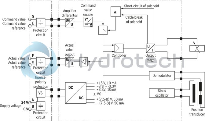
1. Switch-on procedure/Fault behavior
After applying the supply voltage of 24 V, the electronics are ready for operation provided that the following conditions are met:
Supply voltage UB > 18 V DC Connection to solenoid not interrupted Command value line not interrupted and command value > 2.7 mA (interface "G1" only)If one of the conditions is not met, the controllers and the output stage will be blocked and the ready for operation signal to pin 11 (interface "B1" and "G1" only) will be set to 0 V.
2. Actual value output signals
Electrical interfaces "A1" (pin F) and "B1" (pin 6) "A1": 0.35 V … +10 V corresponds to 0% … 100% valve opening; control spooll in seat position if actual value < -2.5 V "B1": 0 V … +10 V corresponds to 0% … 100% valve opening; control spool in seat position if actual value < -1.5 V Electrical interface "G1" (pin 6) 4 mA … +20 mA corresponds to 0% … 100% valve opening; control spool in seat position if actual value < 2.7 mABlock diagram / controller function block
Version 6 + PE
Block diagram / controller function block
Version 11 + PE

Notices:
Electrical interface "A1" in opening direction: Valve active if command value ≥ 0.5 V in closing direction: Valve deactivated if command value ≤ 0.3 V ("on seat") Electrical interfaces "B1" and "G1" in opening direction: Valve active if enable pin 3 is set, command value > -1 V ("B1") or > 2 mA ("G1") in closing direction: Valve deactivated if enable pin 3 is not set, command value < -1 V ("B1") or < 2 mA ("G1") ("on seat")|
Command value |
"B1" and "G1" |
"A1" |
|
Without enable |
 |
– |
|
0 V |
 |
|
|
>0 V … 0.35 V |
 |
|
|
>0.35 V … <0.5 V |
|
|
|
>0.5 V |
|
Connector pin assignment
|
Pin |
Core marking 1) |
Interface assignment |
|||
|
6 + PE |
11 + PE |
"A1" (6 + PE) |
"B1" (11 + PE) |
“G1” (11 + PE) |
|
|
A |
1 |
1 |
Supply voltage 24 VDC |
||
|
B |
2 |
2 |
GND |
||
|
C |
3 |
3 |
Reference potential actual value |
Enable input 24 VDC (high ≥12 V; low ≤5 V) |
|
|
D |
4 |
4 |
Command value 0 … 10 V |
Command value 4 … 20 mA |
|
|
E |
5 |
5 |
Reference potential command value |
||
|
F |
6 |
6 |
Actual value 0 … 10 V |
Actual value 4 … 20 mA |
|
|
7 |
7 |
Reference potential actual value |
|||
|
8 |
8 |
– |
|||
|
9 |
9 |
– |
|||
|
10 |
10 |
– |
|||
|
11 |
11 |
– |
Switching output 24 V – fault-free operation (supply voltage -1 V)/fault (0 V) or power circuit signal), maximum 50 mA |
||
|
PE |
PE |
green-yellow |
Functional ground (directly connected to valve housing) |
||
 |
 |
||||
| 1) | Core marking of the connection lines for mating connector with cable set, see "accessories" |
With integrated electronics (OBE)
Dimensions in mm
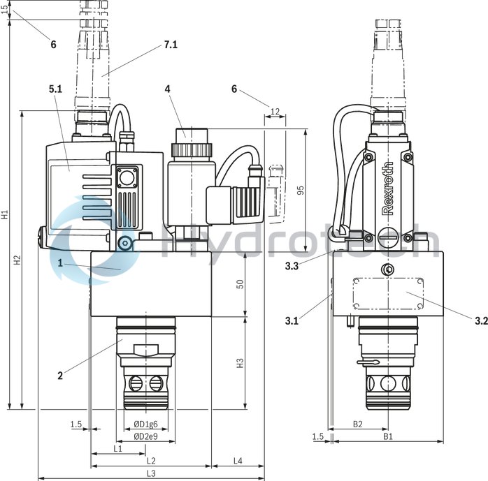
|
1 |
Cover |
|
2 |
Main stage |
|
3.1 |
Name plate NG16 |
|
3.2 |
Name plate NG25 … 40 |
|
3.3 |
Name plate NG50 |
|
4 |
Pilot control valve with proportional solenoid |
|
5.1 |
Integrated electronics with position transducer and analog interface |
|
6 |
Space required to remove the mating connector |
|
7.1 |
Mating connectors for valves with round connector, 6-pole, separate order, see "Accessories" |
|
NG |
ØD1 |
ØD2 |
H1 |
H2 |
H3 |
L1 |
L2 |
L3 |
L4 |
B1 |
B2 |
|
mm |
mm |
mm |
mm |
mm |
mm |
mm |
mm |
mm |
mm |
mm |
|
| 16 | 24 | 32 | 286 | 215 | 56 | 32.5 | 83 | 175 | 42 | 65 | 47 |
| 25 | 34 | 45 | 302 | 231 | 72 | 42.5 | 93 | 175 | 42 | 85 | 47 |
| 32 | 45 | 60 | 315 | 244 | 85 | 50 | 100 | 175 | 42 | 100 | - |
| 40 | 55 | 75 | 335 | 264 | 105 | 62.5 | 125 | 190 | 45 | 125 | - |
| 50 | 68 | 90 | 352 | 281 | 122 | 70 | 140 | 190 | 38 | 140 | - |
Notice:
The dimensions are nominal dimensions which are subject to tolerances.
With external control electronics
Dimensions in mm
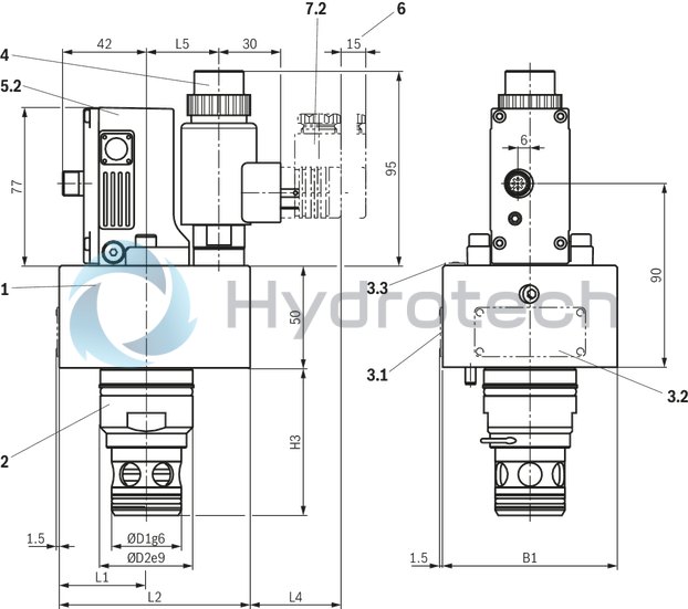
|
1 |
Cover |
|
2 |
Main stage |
|
3.1 |
Name plate NG16 |
|
3.2 |
Name plate NG25 … 40 |
|
3.3 |
Name plate NG50 |
|
4 |
Pilot control valve with proportional solenoid |
|
5.2 |
External control electronics with position transducer. Mating connectors for valves with "M12" connector (separate order, see "Accessories") |
|
6 |
Space required to remove the mating connector |
|
7.2 |
Mating connectors for valves with connector "K4", separate order, see "Accessories" |
|
NG |
ØD1 |
ØD2 |
H3 |
L1 |
L2 |
L4 |
L5 |
B1 |
|
mm |
mm |
mm |
mm |
mm |
mm |
mm |
mm |
|
| 16 | 24 | 32 | 56 | 32.5 | 83 | 42 | 36 | 65 |
| 25 | 34 | 45 | 72 | 42.5 | 93 | 42 | 36 | 85 |
| 32 | 45 | 60 | 85 | 50 | 100 | 42 | 36 | 100 |
| 40 | 55 | 75 | 105 | 62.5 | 125 | 45 | 42 | 125 |
| 50 | 68 | 90 | 122 | 70 | 140 | 38 | 46.5 | 140 |
Notice:
The dimensions are nominal dimensions which are subject to tolerances.
Valve mounting screws (separate order)
|
Size |
Quantity |
Hexagon socket head cap screws |
Material number |
|
16 |
4 |
ISO 4762 - M8 x 30 - 10.9 Tightening torque MA = 35 Nm ±5 Nm |
R913022205 |
|
25 |
4 |
ISO 4762 - M12 x 40 - 10.9 Tightening torque MA = 105 Nm ±15 Nm |
R913022052 |
|
32 |
4 |
ISO 4762 - M16 x 50 - 10.9 Tightening torque MA = 265 Nm ±25 Nm |
R913015664 |
|
40, 50 |
4 |
ISO 4762 - M20 x 60 - 10.9 Tightening torque MA = 500 Nm ±50 Nm |
R913022102 |
Installation bore
(Dimensions in mm)
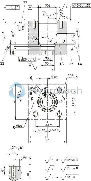
|
8 |
Port X |
|
9 |
Port Y |
|
10 |
Locating hole for locking pin |
|
11 |
Depth of fit |
|
12 |
Control dimension |
|
13 |
Port B may be positioned around the central axis of port A. However, it must be observed that the mounting bores and the control bores are not damaged. |
|
14 |
If a different diameter is used for port B than indicated, the distance from the cover support surface to the bore center must be calculated. |
Installation dimensions according to DIN ISO 7368
|
NG |
16 | 25 | 32 | 40 | 50 | |
|
ØD1H7 |
mm |
32 | 45 | 60 | 75 | 90 |
|
ØD2 |
mm |
16 | 25 | 32 | 40 | 50 |
|
ØD3 |
mm |
16 | 25 | 32 | 40 | 50 |
|
ØD3 max |
mm |
25 | 32 | 40 | 50 | 63 |
|
ØD4H7 |
mm |
25 | 34 | 45 | 55 | 68 |
|
ØD5 |
M8 | M12 | M16 | M20 | M20 | |
|
ØD6 max |
mm |
4 | 6 | 8 | 8 | 10 |
|
ØD7H13 |
mm |
4 | 6 | 6 | 6 | 8 |
|
H1 |
mm |
34 | 44 | 52 | 64 | 72 |
|
H1 1) |
mm |
29.5 | 40.5 | 48 | 59 | 65.5 |
|
H2 |
mm |
56 | 72 | 85 | 105 | 122 |
|
H3 |
mm |
43 | 58 | 70 | 87 | 100 |
|
H4 |
mm |
20 | 25 | 35 | 45 | 45 |
|
H5 min |
mm |
11 | 13 | 13 | 15 | 17 |
|
H6 |
mm |
2 | 2.5 | 2.5 | 3 | 3 |
|
H7 min |
mm |
20 | 30 | 30 | 30 | 35 |
|
H8 |
mm |
2 | 2.5 | 2.5 | 3 | 4 |
|
H9 min 2) |
mm |
0.5 | 1 | 1.5 | 2.5 | 2.5 |
|
H10 |
mm |
8 | 8 | 8 | 8 | 8 |
|
L1 |
mm |
65 | 85 | 100 | 125 | 140 |
|
L2 |
mm |
83 | 93 | 100 | 125 | 140 |
|
L3 |
mm |
32.5 | 42.5 | 50 | 62.5 | 70 |
|
L4 |
mm |
46 | 58 | 70 | 85 | 100 |
|
L5 |
mm |
25 | 33 | 41 | 50 | 58 |
|
L6 |
mm |
10.5 | 16 | 17 | 23 | 30 |
|
L7 |
mm |
23 | 29 | 35 | 42.5 | 50 |
| 1) | Bore center at ØD3 max |
| 2) | Control dimension |
|
Size |
Installation dimensions according to DIN ISO 7368 |
|
16 |
ISO 7368-BA-06-2-A |
|
25 |
ISO 7368-BB-08-2-A |
|
32 |
ISO 7368-BC-09-2-A |
|
40 |
ISO 7368-BD-10-2-A |
|
50 |
ISO 7368-BE-11-2-A |
Notice:
Tolerances according to: General tolerances ISO 2768-mK
Valve amplifier
for proportional directional cartridge valve type 2WFC
VT-MRPA1-2X…WFC
Valve amplifier
for proportional directional cartridge valve type 2WFC
VT-MRPA1-2X…WFC
Component series 2X Suitable to control the pilot-operated proportional directional cartridge valve type 2WFC One amplifier for all valves of type 2WFC-1X Easy selection of the valves to be controlled according to sizes Characteristic curves of the valves stored in the deviceData sheet
Operating instructions
Spare parts & repair
Mating connectors for valves with connector “K4”, without circuitry, standard
3P Z4
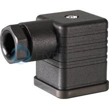
Mating connectors for valves with connector “K4”, without circuitry, standard
3P Z4
For valves with connector “K4” according to EN 175301-803 and ISO 4400, 2-pole + PE, “large cubic connector” Mating connectors for valves with one or two solenoids (individual connection)Data sheet
Spare parts & repair
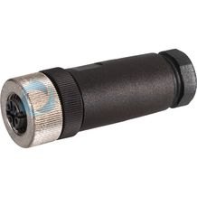
Mating connectors for valves with round connector, 6-pole + PE
7P Z31
Mating connectors for valves with round connector, 6-pole + PE
7P Z31
For valves with round connector according to EN 175201-804, 6-pole + PE as well as 6-pole, compatible with VG 95328Data sheet
Spare parts & repair
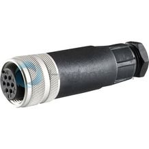
Mating connectors for valves with round connector, 11-pole + PE, shielded, with assembled connection line
12P N11 +
Mating connectors for valves with round connector, 11-pole + PE, shielded, with assembled connection line
12P N11 +
For valves with round connector according to EN 175201-804, 11-pole + PEData sheet
Spare parts & repair
Mating connectors for valves with round connector, 11-pole + PE
12P N11
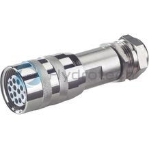
Mating connectors for valves with round connector, 11-pole + PE
12P N11
For valves with round connector according to EN 175201-804, 11-pole + PEData sheet
Spare parts & repair
Mating connectors for valves with round connector, 6-pole + PE, shielded, with assembled connection line
7P Z31 +
Mating connectors for valves with round connector, 6-pole + PE, shielded, with assembled connection line
7P Z31 +
For valves with round connector according to EN 175201-804, 6-pole + PE as well as 6-pole, compatible with VG 95328Data sheet
Spare parts & repair
Mating connectors for sensors and valves with connector “K24”, “K35” and “K72”, M12 x 1
4P Z24
Mating connectors for sensors and valves with connector “K24”, “K35” and “K72”, M12 x 1
4P Z24
For sensors and valves with connector “K24”, “K35” and “K72” Mating connectors M12, 4-pole, line cross-section 0.75 mm2Data sheet
Spare parts & repair