
BOSCH REXROTH
R901441904
Controller Test Rigs
Digital controller HMC 1X
BOSCH REXROTH
MATERIAL: R901441904
SUMMARY: Digital controller HMC 1X
Quantity in stock: 6
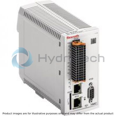
Description
The VT-HMC (Hydraulic Motion Controller) is a digital controller with integrated axis controller and programming functionality according to IEC 61131-3.
The following controller functionalities are available:
Position control Force control Pressure control Substitutional control (position/pressure and force) Velocity control
This enables, amongst others, the following operating modes:
Valve direct control Drive-controlled position control Drive-controlled positioning Positioning block operation
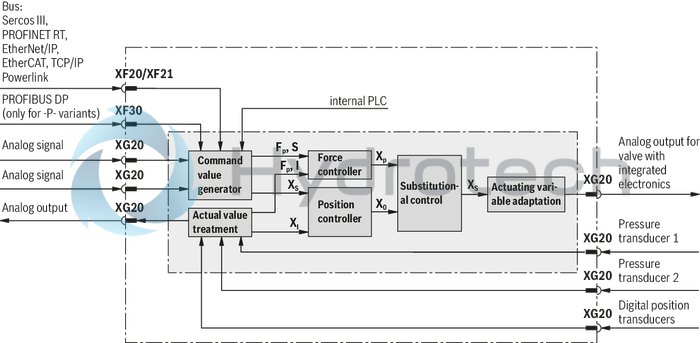
Command value presetting is done via the bus interfaces (XF20/XF21 or XF30), via the analog interface (XG20/XG21) or, alternatively, via an internal PLC program. Axis variant 2 enables independent operation or synchronization control (in preparation) of the axes.
The feedback information of the actual value signals to the superior control system is provided optionally either via the bus interfaces (XF20/XF21 or XF30) or the analog/digital interface (XG20/XG21). For communication with the superior control system, Bosch Rexroth offers function blocks online under www.boschrexroth.com/HMC.
The controller parameters are set via one of the two Ethernet interfaces (XF20/XF21) (integrated switch functionality)
Monitoring
The digital control electronics enable comprehensive monitoring functions/error detection including:
Undervoltage Communication error Cable break for analog sensor inputs (4 ... 20 mA) and digital position measurement system Short-circuit monitoring for analog/digital outputs Monitoring of the microcontroller (watchdog) Temperature of the integrated electronics Over-current of 24 V sensor voltage and digital outputs
IndraWorks MLD or DS PC program
To implement the project planning task and to parameterize the VT-HMC, the user may use the IndraWorks engineering tool (see accessories):
Project planning Parameterization Preparation of the PLC program (IndraWorks MLD requirement) Commissioning Diagnosis Comfortable management of all data on a PC Prerequisite: PC operating system Windows 7
Slot for one SD memory card
The following data may be saved:
PLC program Any other data
Only SD memory cards with SPI bus connection are supported (no SDHC memory cards).
The card must already be inserted when the device is switched on, otherwise it will not be detected. Cards that are not FAT-formatted are formatted automatically (FAT 32).
The maximum capacity of the supported memory cards is 4 GB.
|
01 |
02 |
03 |
04 |
05 |
06 |
07 |
||||||||
|
VT |
– |
HMC |
– |
– |
1X |
/ |
M |
– |
– |
00 |
/ |
00 |
|
Type |
||
|
01 |
Digital axis control for hydraulic drives |
HMC |
|
Axis controls |
||
|
02 |
1 axis |
1 |
|
2 axes |
2 |
|
|
Component series |
||
|
03 |
Component series 10 ... 19 (10 ... 19: unchanged technical data and pin assignment) |
1X |
|
Interface |
||
|
04 |
Multi-Ethernet |
M |
|
Bus connection |
||
|
05 |
With Profibus |
P |
|
Without Profibus |
O |
|
|
Software option |
||
|
06 |
Standard |
00 |
|
Hardware option |
||
|
07 |
Standard |
00 |
Voltage supply
|
Operating voltage |
Nominal voltage |
UB |
24 V DC | ||
|
Lower limit value |
UBmin. |
17.5 V DC | |||
|
Upper limit value |
UBmax. |
30 V DC | |||
|
maximum admissible residual ripple (40 … 400 Hz) |
UPP |
5 V (observe the admissible limits) | |||
|
Total current consumption |
Number of axes |
1 | 2 | ||
|
Running empty |
I |
0.2 … 0.3 A | 0.3 … 0.5 A | ||
|
Max. admissible load 1) |
I |
0.9 … 1.1 A | 1.8 … 2.2 A | ||
|
Power loss (at 24 V) |
W |
< 8 | < 14 | ||
|
External fuse |
3.15 A time-lag | ||||
| 1) | External fuse protection required |
Analog inputs (AI)
|
Number (current or voltage parameterizable) |
4 | 8 | |||
|
Resolution 1) |
14 bit | ||||
|
Voltage inputs (differential inputs) |
Measurement range |
–10 V … +10 V | |||
|
Input resistance |
RE |
200 kΩ ±10 % | |||
|
Linearity at 20 °C |
U |
mV |
< 20 | ||
|
Noise |
U |
mV |
± 15 | ||
|
Temperature drift |
< 12 mV/10 K | ||||
|
Current inputs (reference to AGND) |
Input current |
IE |
4 mA … 20 mA (0 … 20 mA physical) | ||
|
Input resistance |
RE |
100 Ω measuring resistance plus FET plus diode | |||
|
Linearity at 20 °C |
I |
μA |
< 20 | ||
|
Temperature drift |
< 12 μA/10 K | ||||
| 1) | related to ±12 V (1.465 mV/Bit) or 20.7 mA (1.27 μA/Bit) |
Digital inputs (DI)
|
Number |
4 | 8 | ||
|
Low level |
U |
–3 V … 5 V | ||
|
High level |
U |
11 V ... UB | ||
|
Current consumption at high level |
I |
2 mA ... 15 mA | ||
|
Reference potential |
GND | |||
Analog outputs (AO)
|
Number (current or voltage parameterizable) |
2 | 4 | |||
|
Resolution 1) |
16 bit | ||||
|
Voltage outputs |
Output range |
U |
–10 V … +10 V (0 … 10 V via software) | ||
|
Load, min. |
RLmin |
Ω |
1000 | ||
|
Linearity and noise at 20 °C |
U |
μA |
< 35 | ||
|
Temperature drift |
< 12 mV/10 K | ||||
|
Current outputs |
Output range |
I |
0 … 20 mA (4 mA … 20 mA via software) | ||
|
Maximum load |
R |
Ω |
500 | ||
|
Linearity and noise at 20 °C |
I |
mV |
< 25 | ||
|
Temperature drift |
< 12 μA/10 K | ||||
| 1) |
0.334 mV/LSB LSB = Least Significant Bit |
Digital outputs (DO)
|
Number |
4 | 8 | ||
|
Low level |
U |
0 … 3 V | ||
|
High level |
U |
14.5 V … UB | ||
|
Current carrying capacity, max. |
Imax |
50 mA (short-circuit-proof) | ||
|
Signal delay time |
t |
0.5 ms … 1.2 ms (depending on the set performance) | ||
|
Reference potential |
GND | |||
Digital position transducers (encoders):
|
Voltage supply for encoder (optional) |
+5 Venc |
U |
5 VDC ±5 % | ||
|
Vencoder_SSI |
U |
UB ‒ 3 V (max. load) ... UB (running empty) | |||
|
Maximum supply current |
I |
mA |
300 | ||
|
Incremental transducer with TTL output |
Encoder signals |
Two impulse series (A and B, electrically shifted by 90°) and a reference signal (Z) or single ended | |||
|
Signal form |
RS485 | ||||
|
Maximum input frequency |
kHz |
250 | 250 | ||
|
SSI transducer |
Coding 1) |
Gray | |||
|
Data width 1) |
18 ... 28 Bit | ||||
|
Transfer frequency |
80 ... 500 kBit/s | ||||
|
Line receiver/driver |
RS485 | ||||
|
Endat encoder |
2.2 | ||||
| 1) | Due to the higher control quality, an SSI transducer with clock synchronization should be used |
Other information
|
Bus systems 1) |
PROFIBUS DP (max. 12 MBaud acc. to IEC 61158), Sercos III, PROFINET RT, EtherNet/IP, EtherCAT, Powerlink | ||||
|
Parameterization interface |
Ethernet | ||||
|
Scan time position controller (minimum) |
ms |
0.5 | |||
|
Booting time |
< 15 sec (from switch on until the position control system is active) | ||||
|
Supply for sensors Vencoder_ANA |
Power supply |
U |
UB ‒ 4 V (max. load) ... UB ‒ 2.5 V (running empty) | ||
|
Maximum supply current |
I |
mA |
300 | ||
|
Environmental conditions, other specifications |
Type of protection according to EN 60529 |
IP 20 | |||
|
Ambient temperature range |
°C |
-20 … +60 | |||
|
Maximum admissible temperature change |
5 °C/min | ||||
|
Transport temperature range |
°C |
-40 … +70 | |||
|
Recommended storage temperature with UV protection |
°C |
+5 … +40 | |||
|
Relative air humidity |
10 … 95 % (without condensation) | ||||
|
Altitude, max. |
m |
2000 | |||
|
UV resistance |
Housing is only conditionally UV-resistant. In case of long-term exposure, the colors may change. | ||||
|
Transport shock according to DIN EN 60068-2-27 |
15 g / 11 ms / 3 axes | ||||
|
Sine test according to DIN EN 60068-2-6 |
10 … 500 Hz / maximum of 2 g / 10 cycles / 3 axes | ||||
|
Noise test according to DIN EN 60068-2-64 |
20 … 500 Hz / 2.2 g RMS / 6.6 g peak / 30 min. / 3 axes | ||||
|
Free fall (in original packaging, see 61131-2) |
m |
1 | |||
|
EMC (electro-magnetic compatibility) |
EN 61000-6-2 / EN 61131-2 |
EN 61000-4-2 ESD |
4 kV CD / 8 kV AD with BWK B | ||
|
EN 61000-4-3 HF radiated |
10 V/m (80 … 2700 MHz) with BWK A | ||||
|
EN 61000-4-4 Burst |
2 kV with BWK B | ||||
|
EN 61000-4-5 Surge |
0.5 kV / (sym. / unsym.) with BWK B | ||||
|
EN 61000-4-6 HF conducted |
10 Veff (150 kHz … 80 MHz) with BWK A | ||||
|
EN 61000-4-8 Magnetic field 50/60 Hz |
100 A/m with BWK A | ||||
|
EN 61000-6-3 / EN 61000-6-4 / EN 61131-2 |
EN 55016-2-1 Interference voltage |
0.15 … 30 MHz, class A, EN 55022 | |||
|
EN 55016-2-3 Radio interference field strength |
30 … 1000 MHz, class A, EN 55022 | ||||
|
Installation position |
Vertical. For the breathing of the assembly, the ventilation slots of the top and bottom side must be at least 2 cm away from covers, walls, etc. | ||||
|
Installation |
Top hat rail TH 35-7.5 or TH 35-15 according to EN 60715 | ||||
|
Housing material |
Glass-fiber reinforced polyamide plastic | ||||
|
Resistance against aggressive media |
Contact with conductive dusts is not admissible. Avoid contact with hydraulic fluids. | ||||
|
Weight |
m |
kg |
0.6 | ||
|
Conformity |
CE according to the EMC directive, CE according to the RoHS directive | ||||
| 1) | With the EtherCAT (profile CoE) and Powerlink bus systems, support of the second axis is only possible upon request |
For applications outside these parameters, please consult us!
Overview of the controller functions
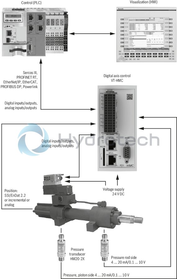
System overview (example)
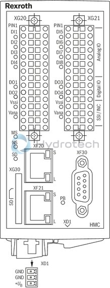
Pin assignment VT-HMC-.-1X
|
XG20, XG21 2), encoder/DIO/AIO |
|||
|
Signal |
Pin |
Pin |
Signal |
|
Vgeber_ANA (UB) |
a1 |
b1 |
AGND |
|
Ai1+ |
a2 |
b2 |
Ai1–/Cin1 1) |
|
Ai2+ |
a3 |
b3 |
Ai2–/Cin2 1) |
|
Ai3+ |
a4 |
b4 |
Ai3–/Cin3 1) |
|
Ai4+ |
a5 |
b5 |
Ai4–/Cin4 1) |
|
Ao1 |
a6 |
b6 |
AGND |
|
Ao2 |
a7 |
b7 |
AGND |
|
Di1 |
a8 |
b8 |
Di2 |
|
Di3 |
a9 |
b9 |
Di4 |
|
Do1 |
a10 |
b10 |
Do2 |
|
R– |
a11 |
b11 |
R+ |
|
CLK–/A– |
a12 |
b12 |
CLK+/A+ |
|
Data‒/B‒ |
a13 |
b13 |
Data+/B+ |
|
+5Venc |
a14 |
b14 |
GND |
|
Vgeber_SSI (UB) |
a15 |
b15 |
GND |
| 1) | Wire current inputs (Cin) only at pin b2 … b5, leave pin a2 … a5 open. Reference potential: AGND (see also Notes in the operating instructions 30239-B) |
| 2) | Only with axis variant 2 XG20 and XG21 can be swapped. The scope of delivery of the two axis variants includes coding pins. For further information, please refer to RE30239-B. |
|
XF20, XF21 |
|
|
Ethernet connections |
|
|
Signal |
Pin |
|
TD+ |
1 |
|
TD– |
2 |
|
RD+ |
3 |
|
– |
4 |
|
– |
5 |
|
RD– |
6 |
|
– |
7 |
|
– |
8 |
|
XD1, Power |
|
|
Pin |
Signal |
|
1 |
GND |
|
2 |
GND |
|
3 |
+UB |
|
XF30, PROFIBUS DP (only for P variant) |
|
|
Pin |
Signal |
|
1 |
reserved |
|
2 |
reserved |
|
3 |
RxD/TxD-P |
|
4 |
CNTR-P |
|
5 |
DGND |
|
6 |
VP |
|
7 |
reserved |
|
8 |
RxD/TxD-N |
|
9 |
reserved |
Dimensions in mm
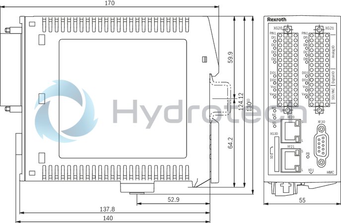
| 1) | Plus 15 mm for connecting/disconnecting the plug-in connector |
|
Status LED |
Display status |
|
Module (MS) |
|
|
Off |
No voltage supply |
|
Green-red, flashing |
Initialization |
|
Green, flashing |
Drive ready for operation |
|
Green |
Drive active |
|
Orange, flashing |
Warning |
|
Red, flashing |
Error |
|
Network status (NS) |
|
|
Off |
No voltage supply |
|
Green |
Operation |
|
SD card (SD) |
|
|
Off |
No SD card available |
|
Green, flashing |
SD card not ready for operation |
|
Green |
SD card available and ready for operation |
|
digital inputs (Di1 ... Di8) 1) |
|
|
Off |
Logic input “0” |
|
Green |
Logic input “1” |
|
digital outputs (Do1 ... Do4, V∡) 2) |
|
|
Off |
Logic output “0” |
|
Orange |
Logic output “1” |
|
Profibus (PB) |
|
|
Off |
Bus not active |
|
Green |
Bus in “Data_Exchange” status |
| 1) | 1-axis variant Di1 ... Di4 |
| 2) | 1-axis variant Do1 ... Do2 |
Notices:
For a detailed description of the diagnosis LEDs, please refer to the functional description Rexroth HydraulicDrive HDx20.
Product documentation for VT-HMC:
Data sheet 30239 (this data sheet) Operating instructions 30239-B CE declaration of conformity (available from Bosch Rexroth upon request) Operation VT-HMC (from 18V12 software version): Functional description Rexroth HydraulicDrive from HDx20 1) Parameter description Rexroth HydraulicDrive from HDx20 RE30330-PA Description of diagnosis Rexroth HydraulicDrive from HDx20 RE3030-WA Library description Rexroth HydraulicDrive, Rexroth IndraMotion MLD (2G), libraries from HDx20 MLD application description General information on the maintenance and commissioning of hydraulic components: Data sheet 07800 / 07900Commissioning software and documentation on the Internet: www.boschrexroth.com/HMC
Maintenance instructions:
The devices have been tested in the plant and are supplied with default settings. Only complete devices can be repaired. Repaired devices are returned with default settings. User-specific settings will not be applied. The machine end-user will have to re-transfer the corresponding user parameters.
Notes:
The supply voltage must be permanently connected; otherwise bus communication is not possible. Connectors may only be plugged or unplugged in the de-energized condition. In particularly EMC-sensitive environments, additional measures must be taken (depending on the application, e.g. shielding, filtration) 2) Wiring information Maximum possible clearance between signal and load lines. Do not lead signal lines through magnetic fields. If possible, install signal lines without intermediate terminals. Do not install signal lines in parallel to the load lines. Connect cable shields (see operating instructions) For digital inputs and outputs, the max. recommended cable length is 30 m. Only use shielded lines for sensors (incremental, absolute or analog). Max. recommended cable length: 50 m; also observe the sensor manufacturers’ information. The signals of the connector XG20/XG21 are not galvanically separated. A potential reference therefore always has to be established when connecting external devices. For additional notices, see IndraWorks online help and operating instructions 30239-B. The upper and lower ventilation slots must not be concealed by adjacent devices in order to provide for sufficient cooling. Observe the installation information in the operating instructions 30239-B.1) The documentation is available as online help in IndraWorks.
2) To use the HMC for household or small business applications, special precautions, such as installation of a shielded housing and appropriately approved filter systems, are required to fulfill the emission requirements according to EN61000-6-3.