
BOSCH REXROTH
R904100644
Power Units
Power units: UPE 5
BOSCH REXROTH
MATERIAL: R904100644
SUMMARY: Power units: UPE 5
Quantity in stock: 0

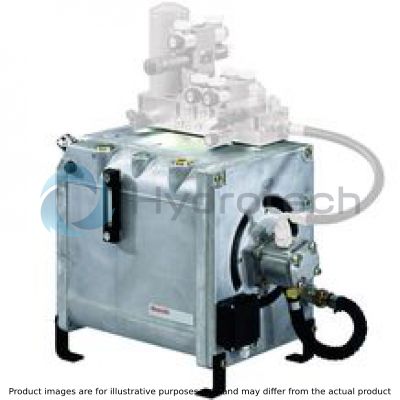
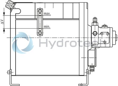
Thanks to its concept, the drive module type UPE 5 can be constructed with very compact dimensions. The pump (2) is driven by means of an electric motor (1). Electric motor and pump are connected without coupling. The pump shaft is plugged into the hollow drilled shaft end of the electric motor. In this way, the length of the pump/motor group is kept to a minimum. The pump (2) sucks in the hydraulic fluid from the tank (4) through the suction tube (3) and delivers it to the hydraulic control. The hydraulic fluid flowing back from the control can be led through the oil/air cooler (5) via connections K1 and K2. The cooled hydraulic fluid than gets back into the tank. By means of the axial fan wheel (6) mounted at the electric motor, cold fresh air is sucked in through the oil/air cooler (5). In this way, the hydraulic fluid and the electric motor are cooled. The tank (4) can be filled through the filling plug (7). The oil level can be monitored by means of the oil level display (8). The tank is closed by a tank cover (9). At the cover, the pump/motor group (1; 2) and the terminal box (10) are attached. The drive module is delivered ready for connection.
Optionally, the drive module can be equipped with an electric oil level and oil temperature monitoring and a complete hydraulic control (see 51156), e.g. filter, accumulator and valves.
Upon request, oil-water cooling, oil pan according to Water Resources Act (WHG), double pump as well as an additional tank are also possible.
Attention!
The drive module may heat up during operation ⇒ Risk of injury!
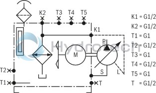
Symbol for control pump (A10VSO, V7)
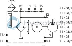
Symbol for displacement pump (GF2, AZ)
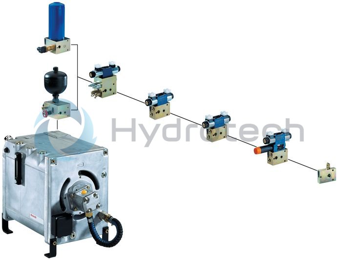
Mounting IH15B control module
The control modules for the UPE5 drive module serves the realization of complete hydraulic controls. They can be fitted and mounted individually.
The filter or accumulator safety module establishes the connection of the hydraulic control to port K2 of the drive module.
The IH15B control modules (in this connection see data sheet 51156) with the connection modules can be attached to the filter or accumulator safety module.
Ordering code
|
01 |
02 |
03 |
04 |
05 |
06 |
07 |
08 |
|||||
|
UPE 5 |
‒ |
1X |
/ |
‒ |
‒ |
‒ |
* |
|
01 |
Drive modules |
UPE 5 |
|
|
02 |
Component series 10 ... 19 (10 ... 19: unchanged installation and connection dimensions) |
1X |
|
|
Drive power |
|||
|
03 |
2,2 kW |
2,2 |
|
|
3 kW |
3,0 |
||
|
4 kW |
4,0 |
||
|
Pumps |
|||
|
04 |
Axial piston variable pumps |
||
|
A10VSO10DFR1/52R-PPA14N00 |
Data sheet 92073 |
A10VSO10 |
|
|
A10VSO18DFR1/31R-PPA12N00 |
Data sheet 92712 |
A10VSO18 |
|
|
Internal gear pumps |
|||
|
PGF2-2X/006RE01VE4 |
Data sheet 10213 |
GF2/006 |
|
|
PGF2-2X/008RE01VE4 |
GF2/008 |
||
|
PGF2-2X/011RE01VE4 |
GF2/011 |
||
|
PGF2-2X/013RE01VE4 |
GF2/013 |
||
|
PGF2-2X/016RE01VE4 |
GF2/016 |
||
|
External gear pumps |
|||
|
AZPF-1X-004RAB01MB |
Data sheet 10089 |
AZ/004 |
|
|
AZPF-1X-005RAB01MB |
AZ/005 |
||
|
AZPF-1X-008RAB01MB |
AZ/008 |
||
|
AZPF-1X-011RAB01MB |
AZ/011 |
||
|
AZPF-1X-016RAB01MB |
AZ/016 |
||
|
AZPF-1X-022RAB01MB |
AZ/022 |
||
|
Vane pumps |
|||
|
PV7-1X/10-14RE01MC0-16 |
Data sheet 10515 |
V7/10-14 |
|
|
PV7-1X/10-20RE01MC0-10 |
V7/10-20 |
||
|
PV7-1X/16-20RE01MC0-16 |
V7/16-20 |
||
|
PV7-1X/06-10RA01MA0-10 |
Data sheet 10522 |
V7/06-10 |
|
|
PV7-1X/06-14RA01MA0-07 |
V7/06-14 |
||
|
PV7-2X/20-20RA01MA0-10 |
V7/20-20 |
||
|
PV7-2X/20-25RA01MA0-10 |
V7/20-25 |
||
|
Oil monitoring |
|||
|
05 |
Oil level display |
A |
|
|
Oil level display with level switch |
AN |
||
|
Oil level display and temperature switch |
AT |
||
|
Oil level display with level and temperature switch |
ANT |
||
|
Installation variants |
|||
|
06 |
Horizontal mounting |
H |
|
|
Vertical mounting |
S |
||
|
Wall mounting |
W |
||
|
Set-up of hydraulic control |
|||
|
07 |
Without set-up |
0 |
|
|
With set-up |
1 |
||
|
08 |
Further details in the plain text |
||
Technical data
|
Hydraulic fluid 1) |
Mineral oil HLP according to DIN 51524 part 2 | |
|
Hydraulic fluid temperature range 2) |
°C |
-10 … +70 |
|
Maximum admissible degree of contamination of the hydraulic fluid, cleanliness class according to ISO 4406 (c) 3) |
Class 20/18/15 according to ISO 4406 (c) | |
|
Viscosity range |
See viscosity range of the pumps and the valves | |
|
Direction of rotation |
Right | |
|
Mass 4) |
kg |
75 |
| 1) | Please observe our provisions according to data sheet 07075! |
| 2) | Observe the admissible viscosity range of the pump and the valves! |
| 3) | The cleanliness classes specified for the components must be adhered to in hydraulic systems. Effective filtration prevents faults and simultaneously increases the life cycle of the components. For the selection of the filters, see www.boschrexroth.com/filter. |
| 4) |
Without hydraulic fluid and pump. For the pump weights refer to data sheets 10089, 10213, 10515, 10522, 92712 and 92713. |
Selection table for pump and electric motor with n = 1450 rpm
|
Axial piston variable pumps |
Operating pressure |
Power |
|
pmax |
P |
|
|
bar |
kW |
|
| A10VSO10DFR1/52R-PPA14N00 | 70 | 2.2 |
| 95 | 3 | |
| 125 | 4 | |
| 220 | 2.2 | |
| 3 | ||
| 4 | ||
| A10VSO18DFR1/31R-PPA12N00 | 40 | 2.2 |
| 50 | 3 | |
| 70 | 4 | |
| 250 | 2.2 | |
| 3 | ||
| 4 |
|
Internal gear pumps |
Operating pressure |
Power |
|
pmax |
P |
|
|
bar |
kW |
|
| PGF2-2X/006RE01VE4 | 110 | 2.2 |
| 150 | 3 | |
| 200 | 4 | |
| PGF2-2X/008RE01VE4 | 90 | 2.2 |
| 120 | 3 | |
| 160 | 4 | |
| PGF2-2X/011RE01VE4 | 65 | 2.2 |
| 90 | 3 | |
| 120 | 4 | |
| PGF2-2X/013RE01VE4 | 55 | 2.2 |
| 75 | 3 | |
| 100 | 4 | |
| PGF2-2X/016RE01VE4 | 45 | 2.2 |
| 60 | 3 | |
| 80 | 4 |
|
External gear pumps |
Operating pressure |
Power |
|
pmax |
P |
|
|
bar |
kW |
|
| AZPF-1X-004RAB20MB | 180 | 2.2 |
| 245 | 3 | |
| 250 | 4 | |
| AZPF-1X-005RAB20MB | 130 | 2.2 |
| 180 | 3 | |
| 250 | 4 | |
| AZPF-1X-008RAB01MB | 90 | 2.2 |
| 120 | 3 | |
| 200 | 4 | |
| AZPF-1X-011RAB01MB | 65 | 2.2 |
| 90 | 3 | |
| 140 | 4 | |
| AZPF-1X-016RAB01MB | 45 | 2.2 |
| 60 | 3 | |
| 100 | 4 | |
| AZPF-1X-022RAB01MB | 40 | 2.2 |
| 55 | 3 | |
| 75 | 4 |
|
Vane pumps |
Operating pressure |
Power |
|
pmax |
P |
|
|
bar |
kW |
|
| PV7-10X/10-14RE01MC0-16 | 50 | 2.2 |
| 65 | 3 | |
| 90 | 4 | |
| 160 | 2.2 | |
| 3 | ||
| 4 | ||
| PV7-1X/10-20RE01MC0-10 | 35 | 2.2 |
| 50 | 3 | |
| 65 | 4 | |
| 100 | 2.2 | |
| 3 | ||
| 4 | ||
| PV7-1X/16-20RE01MC0-16 | 35 | 2.2 |
| 50 | 3 | |
| 65 | 4 | |
| 160 | 2.2 | |
| 3 | ||
| 4 | ||
| PV7-1X/06-10RA01MA0-10 | 70 | 2.2 |
| 100 | 3 | |
| 4 | ||
| 2.2 | ||
| 3 | ||
| 4 | ||
| PV7-1X/06-14RA01MA0-07 | 50 | 2.2 |
| 70 | 3 | |
| 4 | ||
| 2.2 | ||
| 3 | ||
| 4 | ||
| PV7-2X/20-20RA01MA0-10 | 35 | 2.2 |
| 50 | 3 | |
| 65 | 4 | |
| 100 | 2.2 | |
| 3 | ||
| 4 | ||
| PV7-2X/20-25RA01MA0-10 | 30 | 2.2 |
| 40 | 3 | |
| 55 | 4 | |
| 100 | 2.2 | |
| 3 | ||
| 4 |
Electric motor
The electric motor is designed for the operating mode according to VDE 0530 part 1 (EN 60034) for continuous operation S1 within the nominal power range. The electric motor complies with insulation class F and protection class IP55.
The electric motor is to be connected so that it rotates clockwise (clockwise direction of rotation).
It can be used at mains with the frequency 50 Hz or 60 Hz without changes.
Technical data electric motor
|
Voltage 1) |
U |
V |
400/690 ±6 % Δ/Y |
|
Frequency |
f |
Hz |
50 / 60 |
|
Operating mode |
S1 continuous operation | ||
|
Insulation class |
F (winding) | ||
|
Protection class |
IP55 | ||
|
Number of poles |
4 | ||
| 1) | Other voltages upon request. |
Frequency 50 Hz
|
Power |
Speed |
Power factor |
Nominal flow with |
|
|
|
cos φ |
400 V |
|
kW |
rpm |
|
A |
| 2.2 | 1440 | 0.77 | 5.2 |
| 3 | 1415 | 0.76 | 7 |
| 4 | 1390 | 0.73 | 9.8 |
Frequency 60 Hz
|
Power |
Speed |
Power factor |
Nominal flow with |
|
|
|
cos φ |
400 V |
|
kW |
rpm |
|
A |
| 2.23 | 1710 | 0.84 | 4.8 |
| 3 | 1700 | 0.83 | 6.4 |
| 4 | 1680 | 0.77 | 9.3 |
Electro-magnetic compatibility of devices (EMC)
According to the “Act on the electro-magnetic compatibility of devices (§2, subsection 4)” and Directive 89/336 EEA, the drive module is no operationally reliable device.
In order to prevent electro-magnetic interferences that might occur, an interference suppression element e.g. type 23 050, 3 x 400 VAC, 50-60 Hz by Murr-Elektronik (D-71570 Oppenweiler) is recommended.
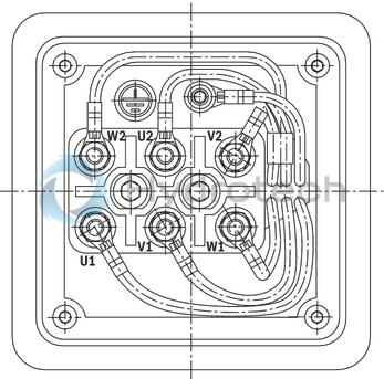
Terminal assignment in the terminal box at the drive module
At the factory
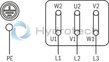
Customer side: Δ triangle U = 400 V
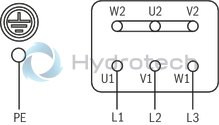
Customer side: Y star U = 690 V
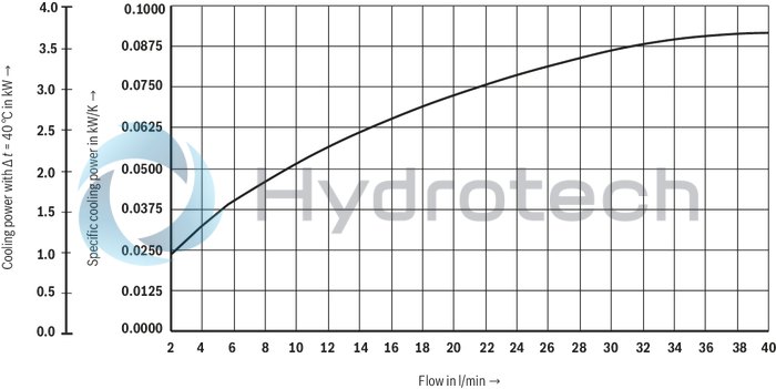
Oil-air cooler 1)
By means of the oil-air cooler, high power density (ratio between drive power and tank size) of the UPE 5 drive module is achieved.
In this way, the drive module with the oil-air cooler can be used in continuous operation. The maximum operating pressure of the oil-air cooler is pmax = 10 bar.
| 1) | On request, oil-water coolers are also possible! |
For applications outside these parameters, please consult us!
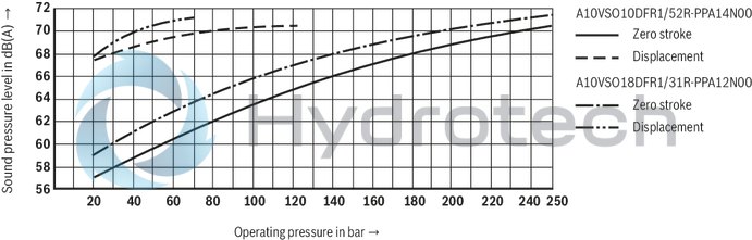
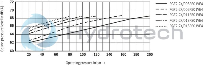
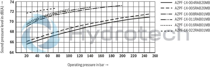
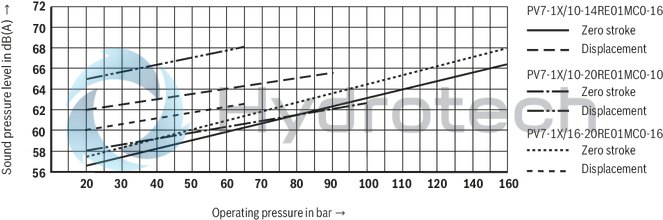
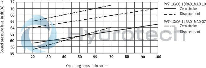
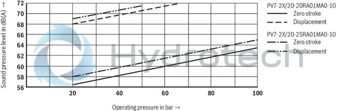
Sound pressure level
(measured with n = 1450 min–1, ν = 41 mm2/s and ϑ = 50 °C)
Sound pressure level for axial piston variable displacement pump A10VSO (in this connection see data sheet 92712, 92713)
Sound pressure level for internal gear pump PGF2-2X (in this connection see data sheet 10213)
Sound pressure level for external gear pump AZPF-1X/ (in this connection see data sheet 10089)
Sound pressure level for vane pump PV7-1X (in this connection see data sheet 10515)
Sound pressure level for vane pump PV7-1X (in this connection see data sheet 10522)
Sound pressure level for vane pump PV7-2X (in this connection see data sheet 10522)
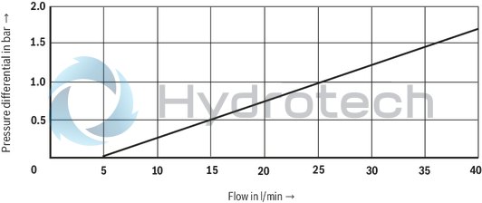
Δp - qv characteristic curve
(measured with ν = 41 mm2/s and ϑ = 50 °C)
Machine tools Lifting platforms Conveyors Test stands Winding machines
Water cooler (optional)
Water cooler on request.
Level switch (option)
The level switch is used for the electric monitoring of the hydraulic fluid filling level. If the minimum oil level is reached, the contact opens and thus gives a signal to the control.
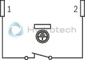
Terminal assignment
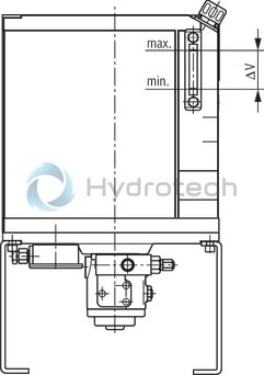
Maximum filling level
Minimum filling level
Technical data
|
Maximum voltage |
V AC/DC |
50 |
|
Maximum current consumption |
A |
0.25 |
|
Maximum power consumption |
W |
3 |
|
Protection class |
IP65 | |
|
Contact type |
Normally closed contact | |
Temperature switch (option)
By means of the temperature switch, the drive module is protected against operation of inadmissibly high hydraulic fluid temperatures. The temperature switch has a fixedly set switching point switching at a hydraulic fluid temperature of 70 °C. The switch-back hysteresis is approx. 15 K.
The temperature switch is screwed into connection T2 in the tank.
Terminal assignment
Temperature ≤ 70 °C
Temperature > 70 °C
Technical data
|
Maximum voltage |
V |
230 |
|
Maximum current consumption |
A |
2 |
|
Protection class |
IP65 | |
|
Contact type |
Normally closed contact | |
Oil tray (option)
Material no. R901271094
Color: RAL 7035 "Light gray"
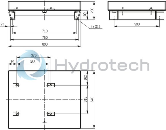
Installation variant: Horizontal mounting
Dimensions in mm
|
Filling volume |
A |
B |
C |
|
l |
mm |
mm |
mm |
| 5 | 600 | 105 | 122 |
| 10 | 600 | 205 | 122 |
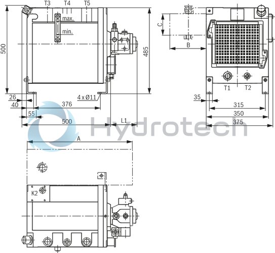
Installation variant: Vertical mounting
Dimensions in mm
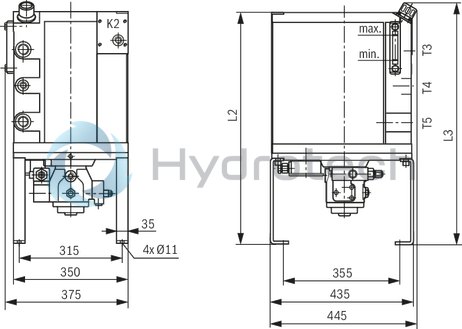
Installation variant: Wall mounting
Dimensions in mm

|
Pump type |
L1 |
L2 |
L3 |
| Axial piston variable pumps |
|
||
|
mm |
mm |
mm |
|
| A10VSO10DFR1/52R-PPA14N00 | 164 | 725 | 755 |
| A10VSO18DFR1/31R-PPA12N00 | 195 | 705 | 735 |
|
Pump type |
L1 |
L2 |
L3 |
| Internal gear pumps |
|
||
|
mm |
mm |
mm |
|
| PGF2-2X/006RE01VE4 | 114 | 630 | 660 |
| PGF2-2X/008RE01VE4 | 117.5 | 705 | 735 |
| PGF2-2X/011RE01VE4 | 123 | 705 | 735 |
| PGF2-2X/013RE01VE4 | 128 | 705 | 735 |
| PGF2-2X/016RE01VE4 | 133 | 705 | 735 |
|
Pump type |
L1 |
L2 |
L3 |
| External gear pumps |
|
||
|
mm |
mm |
mm |
|
| AZPF-1X-004RAB20MB | 85 | 630 | 660 |
| AZPF-1X-005RAB20MB | 86 | 630 | 660 |
| AZPF-1X-008RAB01MB | 90 | 630 | 660 |
| AZPF-1X-011RAB01MB | 95 | 630 | 660 |
| AZPF-1X-016RAB01MB | 103 | 630 | 660 |
| AZPF-1X-022RAB01MB | 115 | 630 | 660 |
|
Pump type |
L1 |
L2 |
L3 |
| Vane pumps |
|
||
|
mm |
mm |
mm |
|
| PV7-1X/10-14RE01MC0-16 | 149 | 705 | 735 |
| PV7-1X/10-20RE01MC0-10 | 149 | 705 | 735 |
| PV7-1X/16-20RE01MC0-16 | 165 | 725 | 755 |
| PV7-1X/06-10RA01MA0-10 | 101 | 630 | 660 |
| PV7-1X/06-14RA01MA0-07 | 101 | 630 | 660 |
| PV7-2X/20-20RA01MA0-10 | 135 | 705 | 735 |
| PV7-2X/20-25RA01MA0-10 | 135 | 705 | 735 |
Filling and removal quantity
Installation variant: Horizontal mounting and wall mounting
Installation variant: Vertical mounting
|
|
Filling quantity |
Removal quantity |
Removal quantity up to switching point of level switch |
|
l |
l |
l |
|
| Installation variant: Horizontal mounting and wall mounting | 23 | 4.5 | 3.5 |
| Installation variant: Vertical mounting | 26 | 3.5 | 2 |
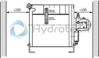
Installation information
Necessary minimum distance to the wall for perfect cooling.
Dimensions in mm
The entire length of the IH15B control should not exceed the length of the UPE5 drive module. Maximum recommended total length I = 500 mm. Please consult us if the entire length of the necessary control is longer.
Check whether the drive module has been professionally connected to the machine to be operated (hydraulically and electrically). For the electrical connections of the motor, the washers and connection bridges included in the delivery must be used. The electric motor must be protected by equipment with overload relay. The latter must be set to the rated current that is specified on the name/rating plate. When installing the drive module, the motor's direction of rotation must imperatively be observed, see arrow for direction of rotation.(Practical control: Hold a sheet of paper close to the cooler. It must be sucked in.) Only fill in the hydraulic fluid through a filter with the required minimum retention rate. Fill the drive module maximally to the upper edge of the inspection glass. The pump must in no case be operated without hydraulic fluid. Start up the pump without load and allow it to run at zero pressure for some seconds in order to provide for sufficient lubrication. The drive module may only be operated with the admissible data. It may moreover only be operated if it is in an unobjectionable condition. When carrying out works at the drive module, the system must be depressurized and de-energized. Unauthorized conversions or modifications which affect the safety and function are not permitted. Available protective devices must not be removed. The generally valid safety and accident prevention regulations must be observed and complied with. Keep the oil-air cooler clean and do not cover it as otherwise, the hydraulic fluid and the electric motor may overheat. The operating pressure of the oil-air cooler must not be exceeded.
Attention!
The drive module may heat up during operation → Risk of injury!
Settings, maintenance and service works at the drive module may only be carried out by authorized, trained and instructed personnel.