
BOSCH REXROTH
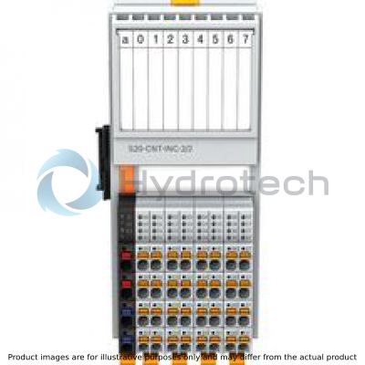
S20-CNT-INC-2/2
R911172539
I/O IndraControl S20 Function modules
BOSCH REXROTH
MATERIAL: R911172539
SUMMARY: I/O IndraControl S20 Function modules
Quantity in stock: 2
Quantity Details:- Hydrotech Stock: 0 can ship May 6, 2024
- Factory Stock: 2 can ship June 24, 2024
Effective as of hardware revision 03, firmware revision 1.20.
This module is designed for use within an S20 station. On the one hand, it is used to acquire fast pulse sequences from sensors and, on the other, to acquire positions by means of incremental encoders. This module combines two counting inputs for the evaluation of fast counting pulses, and two incremental encoder inputs for position detection.
General data
|
Type |
S20-CNT-INC-2/2 | |
|
Color |
Gray | |
|
Weight 1) |
g |
205 |
|
Ambient temperature (operation) |
-25 °C ... +60 °C | |
|
Ambient temperature (storage/transport) |
-40 °C ... +85 °C | |
|
Permissible relative humidity (operation) |
5 % ... 95 %, no dewing | |
|
Permissible relative humidity (storage/transport) |
5 % ... 95 %, no dewing | |
|
Air pressure (operation) |
70 kPa ... 106 kPa (up to 3000 m above sea level) | |
|
Air pressure (storage/transport) |
70 kPa ... 106 kPa (up to 3000 m above sea level) | |
|
Protection type |
IP20 | |
|
Protection class |
III, IEC 61140, EN 61140, VDE 0140-1 | |
|
Installation position |
Any (no temperature derating) | |
| 1) | Including plug and bus base module |
Connection data
|
Type |
S20-CNT-INC-2/2 | |
|
Designation |
S20 connector | |
|
Connection type |
Push-in technology | |
|
Conductor cross-section solid/flexible/AWG |
0.2 mm² ... 1.5 mm² 0.2 mm² ... 1.5 mm² 24 ... 16 |
|
|
Stripping length |
mm |
8 |
Interface local bus
|
Type |
S20-CNT-INC-2/2 | |
|
Connection type |
Bus base module | |
|
Transmission speed |
MBit/s |
100 |
Power supply to logic
|
Type |
S20-CNT-INC-2/2 | |
|
Logic voltage UBus 1) |
V DC |
5 |
|
Typical current consumption from UBus |
mA |
100 |
|
Maximum current consumption from UBus |
mA |
120 |
|
Typical power consumption from UBus |
W |
0.5 |
|
Maximum power consumption from UBus |
W |
0.6 |
| 1) | Via bus base module |
Power supply to peripherals
|
Type |
S20-CNT-INC-2/2 | |
|
Feed to digital input modules UI |
V DC |
24 |
|
Maximum permitted voltage range 1) |
19.2 V DC ... 30 V DC | |
|
Typical current consumption from UI 2) |
mA |
50.5 |
|
Maximum current consumption from UI 3) |
A |
2.5 |
|
Typical power consumption from UI |
W |
1.2 |
|
Maximum power consumption from UI 4) |
W |
60 |
|
Overvoltage/reverse polarity protection supply voltage |
Electronic (35 V, 0.5 s) / parallel diode; with external security 5 A (only for commissioning) | |
|
Guarantee 5) |
A |
≤ 8 |
| 1) | Including all tolerances, including ripple |
| 2) | Internal current consumption; without wiring the terminal points |
| 3) | Depending on the encoder or sensor type used and the load on the digital output |
| 4) | Of which 1.6 W internal losses |
| 5) | Reverse polarity protection up to 5 A |
Counter input
|
Type |
S20-CNT-INC-2/2 | |
|
Number of inputs |
2 (S1, S2) | |
|
Connection type |
Push-in technology | |
|
Description of the input |
EN 61131-2 type 3 | |
|
Input frequency |
Max. 300 kHz (1 channel wired) Max. 100 kHz (more than 1 channel wired or firmware monitoring of the Z signal) |
|
|
Nominal input voltage |
V DC |
24 |
|
Nominal input current per channel |
mA |
2.5 |
|
Input voltage range "0" signal |
-3 V DC ... 5 V DC | |
|
Input voltage range "1" signal |
11 V DC ... 30 V DC | |
|
Permissible cable length |
m |
30 |
Incremental encoder inputs
|
Type |
S20-CNT-INC-2/2 | |
|
Number of inputs |
2 (A1, /A1, B1, /B1, Z1, /Z1; A2, /A2, B2, /B2, Z2, /Z2) | |
|
Connection type |
Push-in technology | |
|
Encoder signals |
Symmetrical and asymmetrical encoders | |
|
Line length |
m |
30 |
Encoder types
|
Type |
S20-CNT-INC-2/2 | |
|
Symmetric incremental encoders |
||
|
Number |
≤ 2 (A, /A, B, /B, (Z, /Z)) | |
|
Signal connection type |
Push-in technology | |
|
Voltage level of the signals |
Difference signal (signal ‒ inverted signal) min. ±0.5 V, max. ±6 V | |
|
Input frequency |
Max. 300 kHz (1 channel wired) Max. 100 kHz (more than 1 channel wired or firmware monitoring of the Z signal) |
|
|
Encoder supply voltage |
5 V DC | |
|
Common-mode voltage range signal ‒ ground |
-10 V ... 13.2 V | |
|
Asymmetric incremental encoders |
||
|
Number |
≤ 2 (A, B, (Z)) | |
|
Signal connection type |
Push-in technology | |
|
Voltage level of the signals ‒ low |
≤ 2.5 V | |
|
Voltage level of the signals ‒ high 1) |
≥ 3.5 V | |
|
Input frequency |
Max. 300 kHz (1 channel wired) Max. 100 kHz (more than 1 channel wired or firmware monitoring of the Z signal) |
|
| 1) | Up to max. 27 V |
Encoder supply
|
Type |
S20-CNT-INC-2/2 | |
|
5 V encoder supply |
||
|
Number |
2 (UE1, UE2) | |
|
Nominal output voltage |
V DC |
5 |
|
Voltage range |
5 V DC ... 5.5 V DC | |
|
Current-carrying capacity |
mA |
≤ 250 |
|
Short-circuit protection |
Electronic | |
|
24 V encoder supply |
||
|
Number |
2 (US1, US2) | |
|
Nominal output voltage |
24 V DC | |
|
Voltage range |
19.2 V DC ... 30 V DC | |
|
Current-carrying capacity |
Typ. 500 mA | |
|
Short-circuit protection |
Electronic | |
Digital inputs
|
Type |
S20-CNT-INC-2/2 | |
|
Number of digital inputs |
8 (CNT: G1, G2, Dir1, Dir2, INC: Ref1, Ref2, L1, L2) | |
|
Connection type |
Push-in technology | |
|
Connectivity technology |
1-wire technology (optional 2-, 3-wire) | |
|
Description of the input |
EN 61131-2 type 3 | |
|
Nominal input voltage |
V DC |
24 |
|
Nominal input current per channel |
mA |
2.5 |
|
Maximum sensor current per channel |
mA |
500 |
|
Input voltage range "0" signal |
-3 V DC ... 5 V DC | |
|
Input voltage range "1" signal |
11 V DC ... 30 V DC | |
|
Permissible cable length to sensor |
m |
30 |
|
Short-circuit protection |
Electronic, per channel | |
|
Overload protection |
Electronic, per channel | |
Digital outputs
|
Type |
S20-CNT-INC-2/2 | |||
|
Number of digital outputs |
2 (Out1, Out2) | |||
|
Connection type |
Push-in technology | |||
|
Connectivity technology |
1-wire technology | |||
|
Nominal output voltage |
24 V DC | |||
|
Output current per channel |
mA |
≤ 500 | ||
|
Nominal load |
Ohmic |
48 Ω; for nominal voltage |
W |
≤ 12 |
|
Lamps |
for nominal voltage |
W |
≤ 12 | |
|
Inductance |
1.2 H, 48 Ω; for nominal voltage |
VA |
≤ 12 | |
|
Short-circuit protection, overload protection of the outputs |
Yes | |||
PROFIBUS telegram data
|
Type |
S20-CNT-INC-2/2 | |
|
Need for parameter data |
byte |
115 |
|
Need for configuration data |
byte |
7 |
Error messages to the higher-level control or computer system
|
Type |
S20-CNT-INC-2/2 | |
|
Error message |
Short-circuit/overload of digital outputs Error on the symmetrical incremental encoder |
|
Electrical isolation/insulation of the voltage ranges
|
Type |
S20-CNT-INC-2/2 | |
|
Test distance |
Test voltage | |
|
5 V supply (logic)/24 V supply (peripherals) |
500 V AC, 50 Hz, 1 min. | |
|
5 V supply (logic)/function earth |
500 V AC, 50 Hz, 1 min. | |
|
24 V supply (peripherals)/function earth |
500 V AC, 50 Hz, 1 min. | |
Mechanical tests
|
Type |
S20-CNT-INC-2/2 | |
|
Vibration resistance 1) |
g |
5 |
|
Shock 2) |
g |
30 |
|
Continuous shock 2) |
g |
10 |
| 1) | Acc. to EN 60068-2-6/IEC 60068-2-6 |
| 2) | Acc. to EN 60068-2-27/IEC 60068-2-27 |
Conformity
|
Type |
S20-CNT-INC-2/2 | ||
|
Conforms with |
|||
|
Testing of interference immunity acc. to EN 61000-6-2 |
Discharge of static electricity (ESD) |
Criterion B; 6 kV contact discharge; 8 kV air discharge acc. to EN 61000-4-2/IEC 61000-4-2 | |
|
Electro-magnetic fields |
Criterion A; field strength: 10 V/m acc. to EN 61000-4-3/IEC 61000-4-3 | ||
|
Fast transients (burst) |
Criterion B; 2 kV acc. to EN 61000-4-4/IEC 61000-4-4 | ||
|
Transient overvoltage (surge) |
Criterion B; supply lines DC: ±0.5 kV/±0.5 kV (symmetric/asymmetric); fieldbus cable shielding: ±1 kV acc. to EN 61000-4-5/IEC 61000-4-5 | ||
|
Line-fed disturbances |
Criterion A; test voltage 10 V acc. to EN 61000-4-6/IEC 61000-4-6 | ||
|
Testing of disturbance transmission acc. to EN 61000-6-3 |
Radio disturbance characteristics |
Class B acc. to EN 55022 | |
|
Approvals |
|
The current approvals can be found at www.boschrexroth.com. |
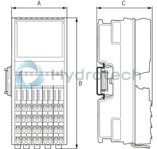
Dimensions
|
Type |
S20-CNT-INC-2/2 | |
|
A |
mm |
53.6 |
|
B |
mm |
126.1 |
|
C |
mm |
54 |
|
Note on dimensions |
The depth applies when using a support rail TH 35-7.5 (acc. to EN 60715). | |