
BOSCH REXROTH
ABSKG-60AL9/VGF2-016/132M/L1NT
R919101941
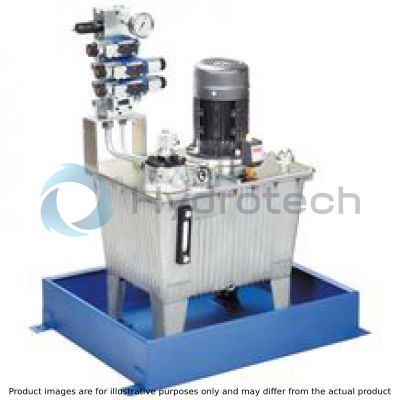
Power Units
ABSKG Small power unit configured
BOSCH REXROTH
MATERIAL: R919101941
SUMMARY: ABSKG Small power unit configured
Quantity in stock: 0
Ordering code
|
01 |
02 |
03 |
04 |
05 |
06 |
07 |
08 |
09 |
10 |
11 |
12 |
13 |
14 |
|||||
|
ABSKG |
- |
AL |
9 |
/ |
/ |
/ |
/ |
|
Power unit |
||
|
01 |
Type ABSKG |
ABSKG |
|
Tank size |
||
|
02 |
20 l |
20 |
|
40 l |
40 |
|
|
60 l |
60 |
|
|
Tank material |
||
|
03 |
Aluminium |
AL |
|
AB standard tank |
||
|
04 |
AB 40-09 |
9 |
|
Kind of set-up: Pump-motor group |
||
|
05 |
Pump power unit vertically installed |
V |
|
Pump type/size (see selection table) |
||
|
06 |
Gear pump, externally geared, < 4 cm3 |
AZPB... |
|
Gear pump, externally geared, ≥ 4 cm3 according to data sheet 10089 |
AZPF... |
|
|
Gear pump, internally geared according to data sheet 10213 |
GF2... |
|
|
Radial piston pump according to data sheet 11263 |
R4... |
|
|
Motor frame size |
||
|
07 |
See selection table |
|
|
Basic power unit type |
||
|
08 |
without air heat exchanger |
ohne Bez. |
|
with air heat exchanger |
L |
|
|
Control variant |
||
|
09 |
Pressure control unit type ABZRD-01/10 to DCCS11010 |
1 |
|
Subplate AB 42-09GG...DMAB |
6 |
|
|
Subplate AB 42-09GG...DMAB with accumulator charging voltage |
7 |
|
|
Number of controls |
||
|
10 |
with control variant 6 and 7 (With control variant 7, one control is required for the accumulator charging valve) |
1 … 6; 8 |
|
Options |
||
|
11 |
Level switch |
N |
|
Oil pan |
O |
|
|
12 |
Hand pump |
P |
|
Thermostat |
T |
|
|
Circuit diagram short symbols (determination after receipt of the order, example) |
||
|
13 |
department in charge |
|
|
serial number |
||
|
Order example: ABSKG-40AL9/VGF2-011/100L/63NT/013A487 |
Selection table tank size 20 l
Set-up pump power units with electric motors efficiency class IE2 or IE3 (according to IEC 60034-30)
at 50 Hz (HLP 46; 50 °C; 32 mm2/s)
|
Pump |
pmax |
Power P at 50 Hz |
Electric motor frame size |
|
bar |
kW |
||
| AZPB 2.0 | 60 | 0.37 | 71 |
| 130 | 0.75 | 80 | |
| 250 / 270 | 1.5 | 90L | |
| AZPB 3.1 | 40 | 0.37 | 100L |
| 80 | 0.75 | 71 | |
| 170 | 1.5 | 80 | |
| 250 | 2.2 | 90L | |
| AZPF-004 | 25 | 0.37 | 100L |
| 65 | 0.75 | 71 | |
| 130 | 1.5 | 80 | |
| 250 / 265 | 3 | 90L | |
| AZPF-005 | 45 | 0.75 | 100L |
| 95 | 1.5 | 112M | |
| 195 | 3 | 80 | |
| 250 / 270 | 4 | 90 | |
| AZPF-008 | 60 | 1.5 | 100L |
| 130 | 3 | 112M | |
| 175 | 4 | 90L | |
| R4-1,6-700 | 315 | 1.5 | |
| R4-3,15-500 | 290 | 3 | 100L |
Selection table tank size 40 l
Set-up pump power units with electric motors efficiency class IE2 or IE3 (according to IEC 60034-30)
at 50 Hz (HLP 46; 50 °C; 32 mm2/s)
|
Pump |
pmax |
Power P at 50 Hz |
Electric motor frame size |
|
bar |
kW |
||
| AZPB 2.0 | 60 | 0.37 | 71 |
| 130 | 0.75 | 80 | |
| 250 / 270 | 1.5 | 90L | |
| AZPB 3.1 | 170 | ||
| 250 | 2.2 | 100L | |
| AZPF-004 | 130 | 1.5 | 90L |
| 250 / 265 | 3 | 100L | |
| AZPF-005 | 95 | 1.5 | 90 |
| 190 | 3 | 100L | |
| 250 / 270 | 4 | 112M | |
| AZPF-008 | 60 | 1.5 | 90L |
| 130 | 3 | 100L | |
| 175 | 4 | 112M | |
| 245 | 5.5 | 132S | |
| GF2-011 | 90 | 3 | 100L |
| 130 | 4 | 112M | |
| 180 | 5.5 | 132S | |
| 210 / 240 | 7.5 | 132M | |
| R4-1,6-700 | 315 | 1.5 | 90L |
| R4-3,15-500 | 290 | 3 | 100L |
| R4-6,3-500 | 315 | 5.5 | 132S |
| R4-8,0-500 | 7.5 | 132M |
Selection table tank size 60 l
Set-up pump power units with electric motors efficiency class IE2 or IE3 (according to IEC 60034-30)
at 50 Hz (HLP 46; 50 °C; 32 mm2/s)
|
Pump |
pmax |
Power P at 50 Hz |
Electric motor frame size |
|
bar |
kW |
||
| AZPF-004 | 130 | 1.5 | 90L |
| 250 / 265 | 3 | 100L | |
| AZPF-005 | 95 | 1.5 | 90 |
| 190 | 3 | 100L | |
| 250 / 270 | 4 | 112M | |
| AZPF-008 | 60 | 1.5 | 90L |
| 130 | 3 | 100L | |
| 175 | 4 | 112M | |
| 245 | 5.5 | 132S | |
| GF2-011 | 90 | 3 | 100L |
| 130 | 4 | 112M | |
| 180 | 5.5 | 132S | |
| 210 / 240 | 7.5 | 132M | |
| GF2-016 | 85 | 4 | 112M |
| 210 | 5.5 | 132S | |
| 165 | 7.5 | 132M | |
| R-3,15-500 | 290 | 3 | 100L |
| R-6,3-500 | 315 | 5.5 | 132S |
| R-8,0-500 | 7.5 | 132M |
Power unit set-up
Power units with/without air heat exchanger in 3 control variants:
|
1 |
Pressure limitation (pressure control unit) |
|
6 |
Pressure limitation with 1 to 8 spaces for vertical stacking NG6 |
|
7 |
Pressure limitation with 1 to 8 spaces for vertical stacking NG6 including accumulator charging circuit |
Technical data
|
Tank size |
l |
20 | 40 | 60 | ||
|
Line connections |
Connection thread according to ISO 1179 (DIN 3852-2 form X) and/or pipe connections according to ISO 8434 part 1 | |||||
|
Hydraulic fluid 1) |
Mineral oil HLP according to DIN 51524; part 2 e.g. with operating temperature 50 °C ISO VG46 DIN ISO 3448 |
|||||
|
Return flow filter with filter element according to DIN 24550 according to data sheet 51424 |
Containers |
l |
20 | 40 | 60 | |
|
|
10TEN0040-H10XLA00-V2,2-M-R3… | 10TEN0063-H10XLA00-V2,2-M-R3… | 10TEN0063-H10XLA00-V2,2-M-R3… | |||
|
Filter rating |
Breathing filter |
µm |
10 | |||
|
Return flow filter |
µm |
10 | ||||
|
Viscosity range with pump type: |
AZPB; AZPF 2) |
mm²/s |
12 … 800 | |||
|
GF2 |
mm²/s |
10 … 300 | ||||
|
R4 |
mm²/s |
10 … 200 | ||||
|
Required cleanliness class for basic power units with pump type 3) |
20/18/15 according to ISO 4406 | |||||
|
Electric motor |
Motor type |
Three-phase asynchronous motor | ||||
|
Efficiency class |
IE1 |
kW |
0.37 | |||
|
IE3 |
kW |
0.75 … 7.5 | ||||
|
Voltage according to IEC 38 U |
≤ 3 kW, 50 Hz |
V |
230; 400 | |||
|
≥ 4 kW, 50 Hz |
V |
400; 690 | ||||
|
Number of pole pairs |
4 | |||||
|
Speed |
rpm |
1450 | ||||
|
Protection class |
IP55 | |||||
|
Heat exchanger |
Type |
Oil-air | ||||
|
Max. operating pressure |
bar |
16 | ||||
|
Type of piping |
Tube forming system for fittings with 24° cone connection or double-edge cutting ring according to ISO 8434 part 1 (DIN 2353) easy/heavy series according to the technical possibilities | |||||
|
Surface treatment |
Steel components pipes; |
Cr(VI)-free metal surface coatings | ||||
|
Oil pan steel design |
Single coat RAL 5010 | |||||
|
Tank aluminum cast |
without additional surface treatment | |||||
|
Connection manifold |
Phosphate coating according to DIN EN 12476 | |||||
|
Components |
Remain in the as-delivered state by the manufacturer. This offers at least temporary corrosion protection. |
|||||
| 1) |
Other hydraulic fluids upon request! ▶ Please observe our provisions according to data sheet 90220. ▶ Different oil types must not be mixed as this might result in degradation and deterioration of the lubricity. ▶ According to the operating conditions, the hydraulic fluid must be renewed at certain intervals. |
| 2) | Recommended range 20 … 100 mm2/s |
| 3) | The required cleanliness classes of the other components must be adhered to in hydraulic systems. Effective filtration prevents faults and at the same time increases the life cycle of the components. |
Heat power losses
|
Containers |
l |
20 | 40 | 60 |
|
Surface with cover |
m² |
0.5 | 1 | 1.3 |
|
Heat power loss P30 |
kW |
0.17 | 0.78 | 0.87 |
|
specific heat power loss |
kW/°C |
0.0055 | 0.026 | 0.029 |
For applications outside these parameters, please consult us!
Characteristic curves (averages) for air heat exchanger
Flow resistance cooling element
Pressure differential Δp dependent on the flow qv with an oil viscosity of 32 mm2/s.

Correction factor k for Δp values dependent on other viscosities
|
kinematic viscosity in mm2/s |
15 |
22 |
32 |
46 |
68 |
100 |
150 |
220 |
460 |
|
k |
0,64 |
0,73 |
1 |
1,28 |
1,62 |
2,65 |
3,9 |
6,9 |
17,1 |
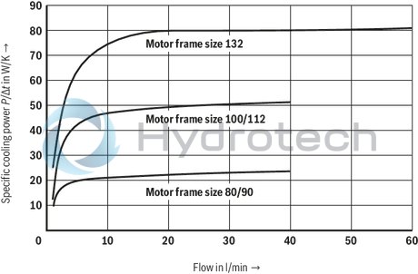
Specific cooling power
of the air heat exchanger dependent on the flow qv and the temperature difference Δt = 1 K (oil inlet to air inlet) at fan wheel speed 1,500 min-1.
Control variant 1
Control variant 1 without air heat exchanger
Control variant 1 with air heat exchanger

Control variant 6
Control variant 6 without air heat exchanger

Control variant 6 with air heat exchanger
Control variant 7
Control variant 7 without air heat exchanger
Control variant 7 with air heat exchanger
| 1) | additional connections with number of controls = 1 (only accumulator charging valve) |
Notice!
No port L3 with 40 l power unit with motor of frame size 132
No port G1/2 on tank with 20 l unit
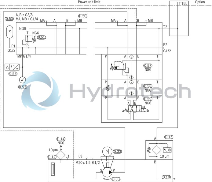
Example of an electric accumulator charging circuit:
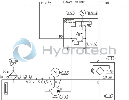
Circuit diagram
|
Pos. |
Type |
|
0.56 |
HEDE 10…/2/ |
|
0.57 |
ZDB6_VA_-4X/_V |
|
0.58 |
R901086591 Z1S 6 P05-4X/V SO104 |
|
0.59 |
R900572186 4WE 6 Y73-6X/EG24N9K4/A12 |
Attention:
Observe the limitations of use of the valves (e.g. switching power limits of the solenoids).
Level switch N
Float switch according to data sheet 50212 with min./max switching contacts and optionally with a temperature contact (70 °C)
|
Tank size |
Minimal switching point normally closed contact 1) |
Maximum switching point, normally open contact 1) |
Temperature contact normally closed contact |
Type |
Part number |
|
mm |
mm |
°C |
|||
| 20 | 120 | 50 | - | ABZMS-35-1X/120F050S-K24 | R901057913 |
| 40 | 165 | 85 | ABZMS-35-1X/165F085S-K24 | R901057914 | |
| 60 | |||||
| 20 | 120 | 50 | 70 | ABZMS-35-1X/120F050S-T70F-K24 | R901057918 |
| 40 | 165 | 85 | ABZMS-35-1X/165F085S-T70F-K24 | R901057920 | |
| 60 |
| 1) | With decreasing level |
|
Tank size |
Minimal switching point normally closed contact 1) |
Switching point (pre-warning) normally open contact 1) |
Temperature contact normally closed contact |
Type |
Part number |
|
mm |
mm |
°C |
|||
| 20 | 120 | 90 | - | ABZMS-35-1X/120F090S-K24 | R901088810 |
| 40 | 165 | 135 | ABZMS-35-1X/165F135S-K24 | R901088811 | |
| 60 | |||||
| 20 | 120 | 90 | 70 | ABZMS-35-1X/120F090S-T70F-K24 | R901088813 |
| 40 | 165 | 135 | ABZMS-35-1X/165F135S-T70F-K24 | R901088814 | |
| 60 |
| 1) | With decreasing level |
|
Tank size |
Minimal switching point normally closed contact 1) |
Switching point (pre-warning) normally open contact 1) |
Type |
Part number |
|
mm |
mm |
|||
| 20 | 120 | 90 | ABZMS-40-1X/120F090S-T2-K24 | R901245525 |
| 40 | 165 | 135 | ABZMS-40-1X/165F135S-T2-K24 | R901245526 |
| 60 |
| 1) | With decreasing level |
|
Tank size |
Maximum filling volume |
Switching point (pre-warning) |
Filling volume at switching point pre-warning |
Minimal switching point |
Filling volume at switching point min |
|
l |
mm |
l |
mm |
l |
|
| 20 | 18 | 90 | 14 | 120 | 11.2 |
| 40 | 33 | 135 | 25 | 165 | 20.8 |
| 60 | 54 | 43 | 37 |
For more versions see data sheet 50220.
Oil pan O
The oil pans have been designed to take up the entire tank volume.|
Tank size |
Oil pan |
Material no. assembly steel version |
Material no. assembly stainless steel version |
Weight |
|
kg |
||||
| 20 | AB 40-09/20 | R901048242 | R901048243 | 19 |
| 40 | AB 40-09/40 | R901048248 | R901048249 | 23 |
| 60 | AB 40-09/60 | R901048245 | R901048246 | 26 |
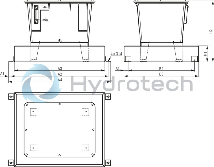
|
Tank size |
A1 |
A2 |
A3 |
A4 |
B1 |
B2 |
B3 |
H1 |
H2 |
|
mm |
mm |
mm |
mm |
mm |
mm |
mm |
mm |
mm |
|
| 20 | 20 | 740 | 680 | 780 | 35 | 380 | 450 | 100 | 363 |
| 40 | 20 | 750 | 690 | 790 | 35 | 520 | 590 | 140 | 483 |
| 60 | 20 | 850 | 790 | 890 | 35 | 580 | 650 | 140 | 535 |
Hand pump P
Assembly kit consisting of:
Hand pump AB42-20/25 Check valve AB21-12 type RE 12S-0,5 / RE S16-0,5 Console|
Tank size |
Type |
Part number |
Weight |
|
kg |
|||
| 20 | MONTAGESATZ AB40-09/20-HANDPUMPE <11,8L | R901009181 | 19 |
| 40 | MONTAGESATZ AB40-09/40-HANDPUMPE <11,8L | R901009022 | 24 |
| 60 | MONTAGESATZ AB40-09/60-HANDPUMPE <11,8L | R901009019 | 29 |
| 40 | MONTAGESATZ AB40-09/40-HANDPUMPE >11,8L | R901009023 | 25 |
| 60 | MONTAGESATZ AB40-09/60-HANDPUMPE >11,8L | R901009021 | 30 |
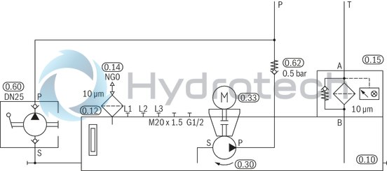
Hydraulic circuit diagram
Dimensions: Hand pump P
tank size 20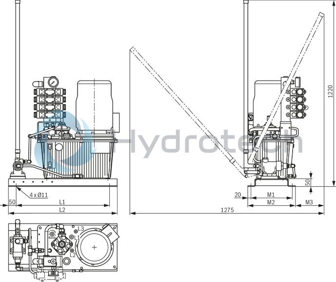
|
Tank size |
L1 |
L2 |
M1 |
M2 |
M3 |
|
mm |
mm |
mm |
mm |
mm |
|
| 20 | 610 | 710 | 270 | 310 | 190 |
Dimensions: Hand pump P
tank size 40; 60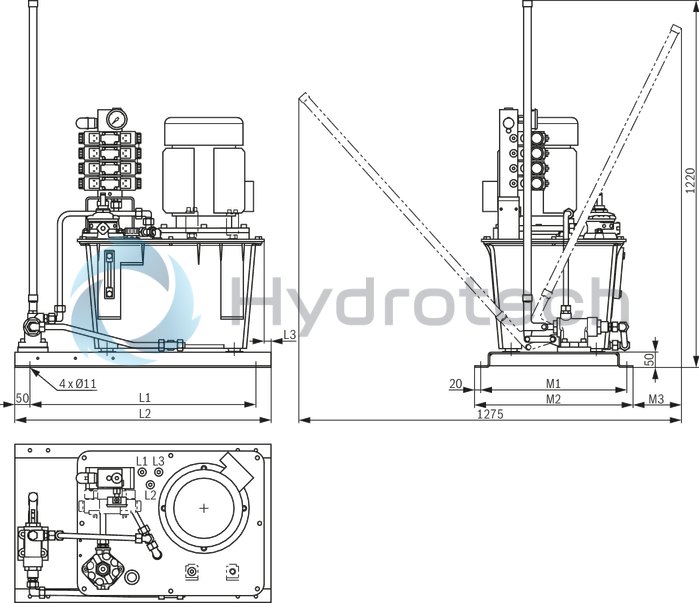
|
Tank size |
L1 |
L2 |
L3 |
M1 |
M2 |
M3 |
|
mm |
mm |
mm |
mm |
mm |
mm |
|
| 40 | 620 | 720 | 13 | 420 | 460 | 175 |
| 60 | 750 | 850 | 23 | 485 | 525 | 165 |
Options hand pump with oil pan on request.
Thermostat T
Electronic contact thermometer according to data sheet 50224 with directly attached display and control unit and temperature display and two programmable switching outputs|
Tank size |
Type |
Part number |
| 40 | ABZMT-1X/0300MS/D0-T2-K24 | R901247784 |
| 60 |
|
Tank size |
Type |
Part number |
| 40 | ABZMT-1X/0300MS/D0-T4-K24 | R901247785 |
| 60 |
For more versions see data sheet 50224.
More options (e.g. console for pressure filter, accumulator station ABSBG, water heat exchanger) are possible on request.
By default, the power units are supplied without labeling (option).
Complete painting is possible as an option.
Float switch with two switching contacts and one temperature contact
ABZMS-35
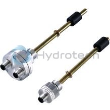
Float switch with two switching contacts and one temperature contact
ABZMS-35
Data sheet
Spare parts & repair
Electronic contact thermometer
ABZMT
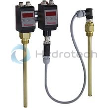
Electronic contact thermometer
ABZMT
Data sheet
Operating instructions
Spare parts & repair
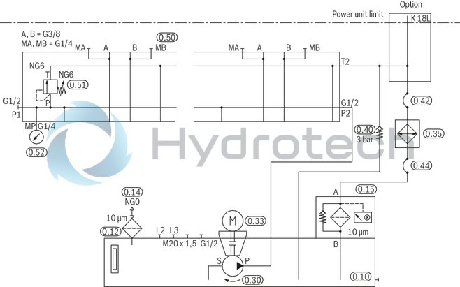
Type ABSKG-20, control variant 1
Dimensions in mm
|
0.10 |
Containers |
|
0.12 |
Oil level display |
|
0.14 |
Filling |
|
0.15 |
Return flow filter |
|
0.30 |
Pump |
|
0.33 |
Electric motor |
|
Pump carrier |
|
|
Coupling |
|
|
0.35 |
Air heat exchanger (basic power unit .../L) |
|
0.42 |
Hose to the heat exchanger |
|
0.44 |
Hose from the heat exchanger to the filter |
|
0.51 |
Pressure control unit |
Line connections
|
without air heat exchanger |
P |
G1/2 |
|
T |
18L | |
|
L2; L3 |
G3/8 | |
|
L1 |
G1/2 | |
|
with air heat exchanger |
P |
G1/2 |
|
K |
18L | |
|
L2; L3 |
G3/8 |
Dimensions
|
Motor frame size |
71 | 80 | 90 | 100 | 112 | ||
|
without air heat exchanger |
A2 |
mm |
- | - | - | - | 15 |
|
H1 |
mm |
490 | 532 | 579 1) | 623 2) | 647 | |
|
with air heat exchanger |
A1 |
mm |
- | - | 32 | 51 | 51 |
|
B1 |
mm |
- | - | - | 29 | 29 | |
|
H2 |
mm |
- | - | 660 | 720 | 744 | |
| 1) | +25 mm with pump R4 |
| 2) | +45 mm with pump R4 |
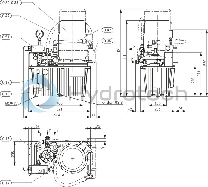
Type ABSKG-40, control variant 1
Dimensions in mm
|
0.10 |
Containers |
|
0.12 |
Oil level display |
|
0.14 |
Filling |
|
0.15 |
Return flow filter |
|
0.30 |
Pump |
|
0.33 |
Electric motor |
|
Pump carrier |
|
|
Coupling |
|
|
0.35 |
Air heat exchanger (basic power unit .../L) |
|
0.42 |
Hose to the heat exchanger |
|
0.44 |
Hose from the heat exchanger to the filter |
|
0.51 |
Pressure control unit |
Line connections
|
without air heat exchanger |
P |
G1/2 |
|
T |
18L | |
|
L3 1) |
G1/2 | |
|
L1 |
G1/2 | |
|
L2 |
G3/8 | |
|
with air heat exchanger |
P |
G1/2 |
|
K |
18L | |
|
L3 1) |
G1/2 | |
|
L2 |
G3/8 |
| 1) | No port L3 with power unit with motor of frame size 132. |
Dimensions
|
Motor frame size |
71 | 80 | 90 | 100 | 112 | 132S | 132M | ||
|
without air heat exchanger |
A2 |
mm |
- | - | - | - | 10 | - | - |
|
B2 |
mm |
- | - | - | - | - | 20 | 20 | |
|
H1 |
mm |
557 | 599 | 646 | 690 | 714 | 728 | 766 | |
|
with air heat exchanger |
A1 |
mm |
- | - | 31 | 50 | 50 | 66 | 66 |
|
B1 |
mm |
- | - | - | 14 | 14 | 30 | 30 | |
|
H2 |
mm |
- | - | 727 | 787 | 811 | 844 | 882 | |
|
H5 |
mm |
- | - | 65 | 30 | 30 | 40 | 50 | |
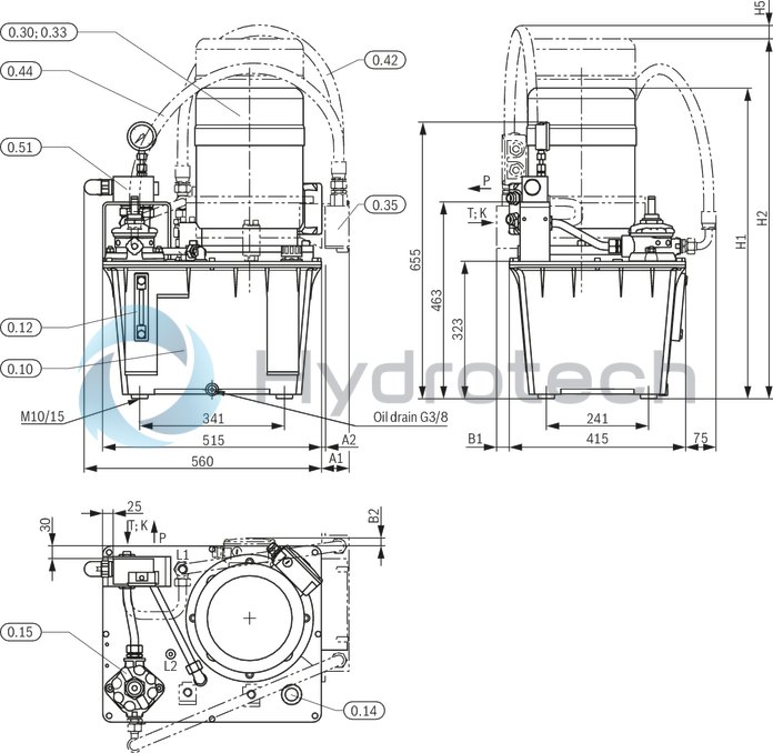
Type ABSKG-60, control variant 1
Dimensions in mm
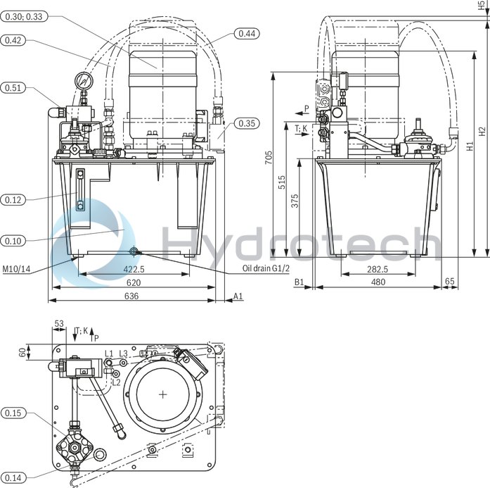
|
0.10 |
Containers |
|
0.12 |
Oil level display |
|
0.14 |
Filling |
|
0.15 |
Return flow filter |
|
0.30 |
Pump |
|
0.33 |
Electric motor |
|
Pump carrier |
|
|
Coupling |
|
|
0.35 |
Air heat exchanger (basic power unit .../L) |
|
0.42 |
Hose to the heat exchanger |
|
0.44 |
Hose from the heat exchanger to the filter |
|
0.51 |
Pressure control unit |
Line connections
|
without air heat exchanger |
P |
G1/2 |
|
T |
18L | |
|
L3 |
G1/2 | |
|
L1 |
G1/2 | |
|
L2 |
G3/8 | |
|
with air heat exchanger |
P |
G1/2 |
|
K |
18L | |
|
L3 |
G1/2 | |
|
L2 |
G3/8 |
Dimensions
|
Motor frame size |
71 | 80 | 90 | 100 | 112 | 132S | 132M | ||
|
without air heat exchanger |
H1 |
mm |
607 1) | 649 1) | 696 | 740 | 764 | 778 | 816 |
|
with air heat exchanger |
A1 |
mm |
- | - | - | - | - | 35 | 35 |
|
B1 |
mm |
- | - | - | - | - | 10 | 10 | |
|
H2 |
mm |
- | - | 777 | 837 | 861 | 894 | 932 | |
|
H5 |
mm |
- | - | 55 | 35 | 25 | 25 | 40 | |
| 1) | Possible motor frame size that is not contained in the selection table of the basic power units for 20 l, 40 l and 60 l tanks. |
Type ABSKG-20, control variant 6
Dimensions in mm
|
0.10 |
Containers |
|
0.12 |
Oil level display |
|
0.14 |
Filling |
|
0.15 |
Return flow filter |
|
0.30 |
Pump |
|
0.33 |
Electric motor |
|
Pump carrier |
|
|
Coupling |
|
|
0.35 |
Air heat exchanger (basic power unit .../L) |
|
0.42 |
Hose to the heat exchanger |
|
0.44 |
Hose from the heat exchanger to the filter |
|
0.51 |
Pressure control unit |
|
0.52 |
Pressure gauge |
Line connections
|
without air heat exchanger |
A |
G3/8 |
|
B |
G3/8 | |
|
L2; L3 |
G3/8 | |
|
P |
G1/2 | |
|
T optional |
18L | |
|
L1 |
G1/2 | |
|
with air heat exchanger |
A |
G3/8 |
|
B |
G3/8 | |
|
L2; L3 |
G3/8 | |
|
P |
G1/2 | |
|
K optional |
18L |
Dimensions
|
Motor frame size |
71 | 80 | 90 | 100 | 112 | ||
|
without air heat exchanger |
A2 |
mm |
- | - | - | - | 15 |
|
H1 |
mm |
490 | 532 | 579 1) | 623 2) | 647 | |
|
with air heat exchanger |
A1 |
mm |
- | - | 32 | 51 | 51 |
|
B1 |
mm |
- | - | - | 29 | 29 | |
|
H2 |
mm |
- | - | 660 | 720 | 744 | |
| 1) | +25 mm with pump R4 |
| 2) | +45 mm with pump R4 |
Dimension H3
|
Number of controls |
1 | 2 | 3 | 4 | 5 | 6 | 8 | |
|
H3 |
mm |
516 | 566 | 616 | 666 | 716 | 766 | 866 |
Attention: The maximum dimensions may differ due to the attached valves.
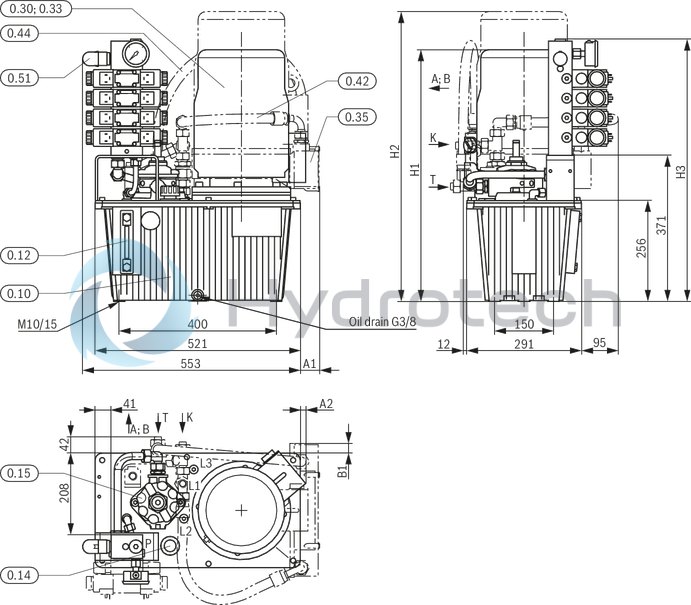
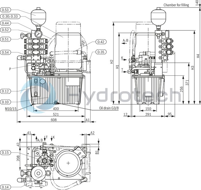
Type ABSKG-40, control variant 6
Dimensions in mm

|
0.10 |
Containers |
|
0.12 |
Oil level display |
|
0.14 |
Filling |
|
0.15 |
Return flow filter |
|
0.30 |
Pump |
|
0.33 |
Electric motor |
|
Pump carrier |
|
|
Coupling |
|
|
0.35 |
Air heat exchanger (basic power unit .../L) |
|
0.42 |
Hose to the heat exchanger |
|
0.44 |
Hose from the heat exchanger to the filter |
|
0.51 |
Pressure control unit |
|
0.52 |
Pressure gauge |
Line connections
|
without air heat exchanger |
A |
G3/8 |
|
B |
G3/8 | |
|
L3 1) |
G1/2 | |
|
with air heat exchanger |
A |
G3/8 |
|
B |
G3/8 | |
|
L3 1) |
G1/2 |
| 1) | No port L3 with power unit with motor of frame size 132. |
Dimensions
|
Motor frame size |
71 | 80 | 90 | 100 | 112 | 132S | 132M | ||
|
without air heat exchanger |
A2 |
mm |
- | - | - | - | 10 | - | - |
|
B2 |
mm |
- | - | - | - | - | 20 | 20 | |
|
H1 |
mm |
557 | 599 | 646 | 690 | 714 | 728 | 766 | |
|
with air heat exchanger |
A1 |
mm |
- | - | 31 | 50 | 50 | 66 | 66 |
|
B1 |
mm |
- | - | - | 14 | 14 | 30 | 30 | |
|
H2 |
mm |
- | - | 727 | 787 | 811 | 844 | 882 | |
|
H5 |
mm |
- | - | 95 | 60 | 60 | 70 | 80 | |
Dimension H3
|
Number of controls |
1 | 2 | 3 | 4 | 5 | 6 | 8 | |
|
H3 |
mm |
608 | 658 | 708 | 758 | 808 | 858 | 958 |
Attention: The maximum dimensions may differ due to the attached valves.
Type ABSKG-60, control variant 6
Dimensions in mm
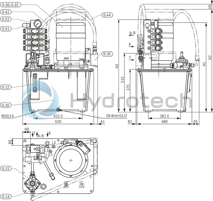
|
0.10 |
Containers |
|
0.12 |
Oil level display |
|
0.14 |
Filling |
|
0.15 |
Return flow filter |
|
0.30 |
Pump |
|
0.33 |
Electric motor |
|
Pump carrier |
|
|
Coupling |
|
|
0.35 |
Air heat exchanger (basic power unit .../L) |
|
0.42 |
Hose to the heat exchanger |
|
0.44 |
Hose from the heat exchanger to the filter |
|
0.51 |
Pressure control unit |
|
0.52 |
Pressure gauge |
Line connections
|
without air heat exchanger |
A |
G3/8 |
|
B |
G3/8 | |
|
L3 |
G1/2 | |
|
P |
G1/2 | |
|
T optional |
18L | |
|
L1 |
G1/2 | |
|
L2 |
G3/8 | |
|
with air heat exchanger |
A |
G3/8 |
|
B |
G3/8 | |
|
L3 |
G1/2 | |
|
P |
G1/2 | |
|
L2 |
G3/8 |
Dimensions
|
Motor frame size |
71 | 80 | 90 | 100 | 112 | 132S | 132M | ||
|
without air heat exchanger |
H1 |
mm |
607 1) | 649 1) | 696 | 740 | 764 | 778 | 816 |
|
with air heat exchanger |
A1 |
mm |
- | - | - | - | - | 35 | 35 |
|
B1 |
mm |
- | - | - | - | - | 10 | 10 | |
|
H2 |
mm |
- | - | 777 | 837 | 861 | 894 | 932 | |
|
H5 |
mm |
- | - | 85 | 65 | 55 | 55 | 70 | |
| 1) | Possible motor frame size that is not contained in the selection table of the basic power units for 20 l, 40 l and 60 l tanks. |
Dimension H3
|
Number of controls |
1 | 2 | 3 | 4 | 5 | 6 | 8 | |
|
H3 |
mm |
658 | 708 | 758 | 808 | 858 | 908 | 1008 |
Attention: The maximum dimensions may differ due to the attached valves.
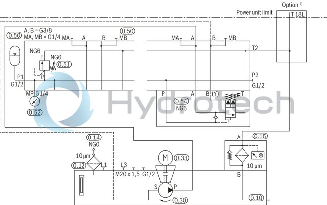
Type ABSKG-20, control variant 7
Dimensions in mm
|
0.10 |
Containers |
|
0.12 |
Oil level display |
|
0.14 |
Filling |
|
0.15 |
Return flow filter |
|
0.30 |
Pump |
|
0.33 |
Electric motor |
|
Pump carrier |
|
|
Coupling |
|
|
0.35 |
Air heat exchanger (basic power unit .../L) |
|
0.42 |
Hose to the heat exchanger |
|
0.44 |
Hose from the heat exchanger to the filter |
|
0.51 |
Pressure valve |
|
0.52 |
Pressure gauge |
|
0.53 |
Hydraulic accumulator |
|
0.54 |
Accumulator charging valve |
Line connections
|
without air heat exchanger |
A |
G3/8 |
|
B |
G3/8 | |
|
L3 |
G3/8 | |
|
P |
G1/2 | |
|
T 1) optional 1) |
18L | |
|
L1 |
G1/2 | |
|
with air heat exchanger |
A |
G3/8 |
|
B |
G3/8 | |
|
L3 |
G3/8 | |
|
P |
G1/2 | |
|
K 1) optional 1) |
18L |
| 1) | Additional connections with number of controls = 1 (only accumulator charging valve) |
Dimensions
|
Motor frame size |
71 | 80 | 90 | 100 | 112 | ||
|
without air heat exchanger |
A2 |
mm |
- | - | - | - | 15 |
|
H1 |
mm |
490 | 532 | 579 1) | 623 2) | 647 | |
|
with air heat exchanger |
A1 |
mm |
- | - | 32 | 51 | 51 |
|
B1 |
mm |
- | - | - | 29 | 29 | |
|
H2 |
mm |
- | - | 660 | 720 | 744 | |
| 1) | +25 mm with pump R4 |
| 2) | +45 mm with pump R4 |
Dimension H3; H4
|
Number of controls |
1 | 2 | 3 | 4 | 5 | 6 | 8 | |
|
H3 |
mm |
511 | 561 | 611 | 661 | 711 | 761 | 861 |
|
H4 |
mm |
717 | 767 | 817 | 867 | 917 | 967 | 1067 |
Attention: The maximum dimensions may differ due to the attached valves.
Type ABSKG-40, control variant 7
Dimensions in mm
|
0.10 |
Containers |
|
0.12 |
Oil level display |
|
0.14 |
Filling |
|
0.15 |
Return flow filter |
|
0.30 |
Pump |
|
0.33 |
Electric motor |
|
Pump carrier |
|
|
Coupling |
|
|
0.35 |
Air heat exchanger (basic power unit .../L) |
|
0.42 |
Hose to the heat exchanger |
|
0.44 |
Hose from the heat exchanger to the filter |
|
0.51 |
Pressure valve |
|
0.52 |
Pressure gauge |
|
0.53 |
Hydraulic accumulator |
|
0.54 |
Accumulator charging valve |
Line connections
|
without air heat exchanger |
A |
G3/8 |
|
B |
G3/8 | |
|
L3 1) |
G1/2 | |
|
P |
G1/2 | |
|
T 2) optional 2) |
18L | |
|
L1 |
G1/2 | |
|
with air heat exchanger |
A |
G3/8 |
|
B |
G3/8 | |
|
L3 1) |
G1/2 | |
|
P |
G1/2 | |
|
K 2) optional 2) |
18L |
| 1) | No port L3 with power unit with motor of frame size 132. |
| 2) | Additional connections with number of controls = 1 (only accumulator charging valve) |
Dimensions
|
Motor frame size |
71 | 80 | 90 | 100 | 112 | 132S | 132M | ||
|
without air heat exchanger |
A2 |
mm |
- | - | - | - | 10 | - | - |
|
H1 |
mm |
557 | 599 | 646 | 690 | 714 | 728 | 766 | |
|
with air heat exchanger |
A1 |
mm |
- | - | 31 | 50 | 50 | 66 | 66 |
|
B1 |
mm |
- | - | - | 14 | 14 | 30 | 30 | |
|
B2 |
mm |
- | - | - | - | - | 20 | 20 | |
|
H2 |
mm |
- | - | 727 | 787 | 811 | 844 | 882 | |
|
H5 |
mm |
- | - | 95 | 60 | 60 | 70 | 80 | |
Dimension H3; H4
|
Number of controls |
1 | 2 | 3 | 4 | 5 | 6 | 8 | |
|
H3 |
mm |
603 | 653 | 703 | 753 | 803 | 853 | 953 |
|
H4 |
mm |
809 | 859 | 909 | 959 | 1009 | 1059 | 1159 |
Attention: The maximum dimensions may differ due to the attached valves.
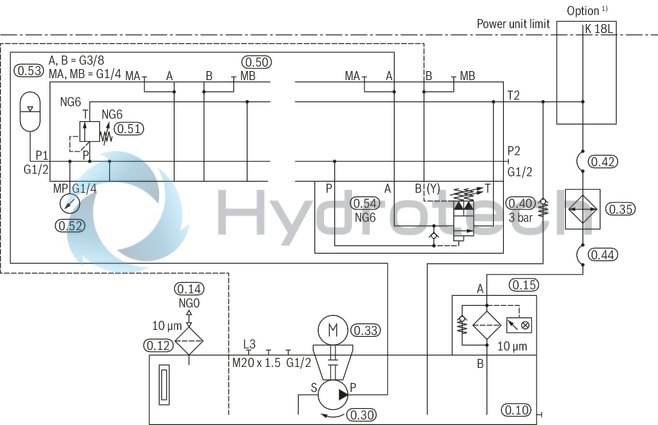
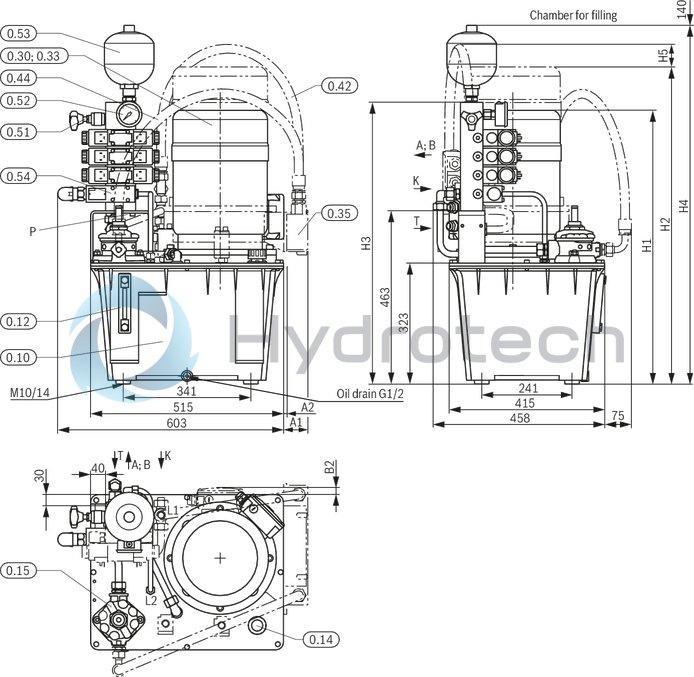
Type ABSKG-60, control variant 7
Dimensions in mm

|
0.10 |
Containers |
|
0.12 |
Oil level display |
|
0.14 |
Filling |
|
0.15 |
Return flow filter |
|
0.30 |
Pump |
|
0.33 |
Electric motor |
|
Pump carrier |
|
|
Coupling |
|
|
0.35 |
Air heat exchanger (basic power unit .../L) |
|
0.42 |
Hose to the heat exchanger |
|
0.44 |
Hose from the heat exchanger to the filter |
|
0.51 |
Pressure valve |
|
0.52 |
Pressure gauge |
|
0.53 |
Hydraulic accumulator |
|
0.54 |
Accumulator charging valve |
Line connections
|
without air heat exchanger |
A |
G3/8 |
|
B |
G3/8 | |
|
L3 |
G1/2 | |
|
P |
G1/2 | |
|
T 1) optional 1) |
18L | |
|
L1 |
G1/2 | |
|
with air heat exchanger |
A |
G3/8 |
|
B |
G3/8 | |
|
L3 |
G1/2 | |
|
P |
G1/2 | |
|
K optional |
18L |
| 1) | Additional connections with number of controls = 1 (only accumulator charging valve) |
Dimensions
|
Motor frame size |
71 | 80 | 90 | 100 | 112 | 132S | 132M | ||
|
without air heat exchanger |
H1 |
mm |
607 1) | 649 1) | 696 | 740 | 764 | 778 | 816 |
|
with air heat exchanger |
A1 |
mm |
- | - | - | - | - | 35 | 35 |
|
B1 |
mm |
- | - | - | - | - | 10 | 10 | |
|
H2 |
mm |
- | - | 777 | 837 | 861 | 894 | 932 | |
|
H5 |
mm |
- | - | 95 | 75 | 65 | 65 | 80 | |
| 1) | Possible motor frame size that is not contained in the selection table of the basic power units for 20 l, 40 l and 60 l tanks. |
Dimension H3; H4
|
Number of controls |
1 | 2 | 3 | 4 | 5 | 6 | 8 | |
|
H3 |
mm |
653 | 703 | 753 | 803 | 853 | 903 | 1003 |
|
H4 |
mm |
859 | 909 | 959 | 1009 | 1059 | 1109 | 1209 |
Attention: The maximum dimensions may differ due to the attached valves.
Project planning information for the use of air heat exchangers:
In power units with air heat exchanger, smoothly switching valves according to data sheet 23183 are to be preferably used in order to reduce pressure peaks in the tank line. Due to the abrupt opening of releasable check valves, application-inherent pressure peaks in the tank line may also occur if smoothly switching valves are used. For unloading large decompression volumes, a free return flow port is available leading directly into the tank. Due to the use of the air heat exchanger in the return line, the flow from the system/of the application is to be observed. (E.g. increase in the flow due to the use of differential cylinders and/or accumulator applications.) For more detailed information on the back pressure to be expected see "Diagrams".Installation, commissioning, maintenance and operating instructions
Hydraulic power units according to this data sheet are exclusively intended for stationary operation. They must be installed under low corrosion conditions at a dry indoor climate.
During installation, the power units are to be included in the equipotential bonding. A connection thread M8 marked with the corresponding earthing symbol is located on the tank cover at the mounting bracket of the control.
The power units may only be operated within the performance limits described in this data sheet with the listed operating media.
The power unit must particularly not be operated above the specified operating pressure range and no values above the maximum settings indicated in the circuit diagram must be set at the pressure relief valve.
Warning!
With basic power units without pressure limitation, pressure limitation equipment. must be provided in the system, usually a pressure relief valve!
Attention!
Pressure adjustment upon commissioning with accumulator charging circuits control variant 7!
The pressure adjustment of the pressure cut-off valve DA 6 VA... must at least be 15 bar lower than that of the accumulator safety valve DBDH 6 K1X/...E.
In this connection, please observe the instructions contained in the following documents which are supplied by the factory together with the power unit and must be available upon installation and commissioning:
Declaration of incorporation in the sense of the EC Machinery Directive 2006/42/EC, annex II B General assembly instructions with information on the transport of the hydraulic power units, assembly instructions 07009-MON General operating instructions for hydraulic power units and hydraulic assemblies, data sheet 07009 Operating instructions diaphragm accumulator type HAD (in version with control variant 7), 50150-B Setting instructions pressure relief valve, direct operated type DBD, DBD...-E, 25402-EVT Hydraulic circuit diagram
Notice in the sense of the EC Machinery Directive 2006/42/EC
The power units are manufactured in accordance with the harmonized standards DIN EN ISO 4413, DIN EN ISO 12100 and DIN EN 60204-1. The hydraulic power unit constitutes partly completed machinery in the sense of the EC Machinery Directive 2006/42/EC. It is exclusively intended for integration into a machine or system or to be assembled with other components to form a machine or system.
The product may be commissioned only if it has been integrated into the machine or system for which it is designed and if the machine or system fully complies with the requirements of the EC Machinery Directive. The hydraulic power unit is not considered to be a safety component in the sense of the EC Machinery Directive 2006/42/EC.
Mating connectors
suitable for the listed float switches according to data sheet 50212/50220;Contact thermometer according to data sheet 50224;Maintenance indicator for return flow filter according to data sheet 51450|
For detailed information see data sheet 08006 |
|||
|
Mating connector for connector K24 |
Mating connector for connector K24 with potted-in PVC cable, 3 m long |
||
|
Denomination |
Part number |
Denomination |
Part number |
|
LEITUNGSDOSE 4P Z24 SPEZ |
R900031155 |
LEITUNGSDOSE 4P Z24M12X1+3MSPEZ |
R900064381 |
Foot AB 40-09 for tank 40; 60
|
Type |
Part number |
Quantity |
|
FUSS AB40-09/1 |
R901044792 |
4 |
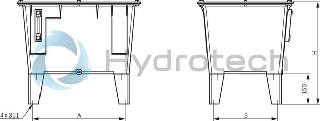
|
Tank size |
A |
B |
H |
|
mm |
mm |
mm |
|
| 40 | 381 | 281 | 463 |
| 60 | 462.5 | 322.5 | 515 |
Return pipe PN16 for drain lines
Material galvanized steel
Pipe connection according to ISO 8434 part 1
Dimensions: Return pipe PN16
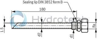
|
Row |
Ra |
d1 |
d2 |
Part number |
|
mm |
mm |
|||
| L light | 10 | G3/8 | 10 | R900086003 |
| 12 | G3/8 | 12 | R900064249 | |
| 15 | G1/2 | 16 | R900064255 | |
| 18 | G1/2 | 16 | R900064254 | |
| S heavy | 16 | G1/2 | 16 | R900053354 |
Filter element
1.
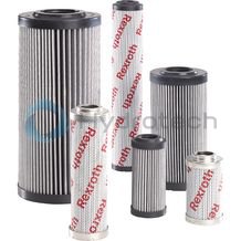
Filter element
1.
Size 0040 … 2500 Pressure differential 330 bar Filter rating 1 µm Filter area 4.8 m² Operating temperature range -10 … +100 °CData sheet
Spare parts & repair
Electronic switching elements
WE-.SP
Electronic switching elements
WE-.SP
Operating temperature -30 … +85 °CData sheet
Spare parts & repair
Electronic switching elements
WE-S02
Electronic switching elements
WE-S02
Max. operating pressure 40 bar Operating temperature -10 … +100 °CData sheet
Spare parts & repair