
BOSCH REXROTH
4WN10Y3X/V/12
R978862205
Directional Spool Valves
Direct. spool valves: WN 10.-3x/
BOSCH REXROTH
MATERIAL: R978862205
SUMMARY: Direct. spool valves: WN 10.-3x/
Quantity in stock: 0
Valves of type WN are fluidically actuated directional spool valves.
They control the start, stop and direction of a flow.
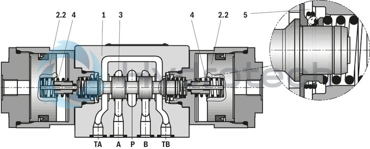
The directional valves basically consist of housing (1), one type of actuation (2.2) (hydraulic actuation cylinder), control spool (3) and one or two return springs (4).
When de-energized, the control spool (3) is held in the central position or in the initial position by the return springs (4) (except for version "O").
The control spool (3) is moved to the desired spool position by means of the types of actuation.
Type 4WN 10 D5X/OF…
Type 4WN 10 E5X/…
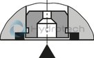
Throttle insert
The use of a throttle insert is required when, due to prevailing operating conditions, flows occur during the switching processes which exceed the performance limit of the valve.
|
01 |
02 |
03 |
04 |
05 |
06 |
07 |
08 |
09 |
10 |
11 |
||
|
WN |
10 |
5X |
/ |
/ |
no code |
* |
|
01 |
3 main ports |
3 |
||
|
4 main ports |
4 |
|||
|
Types of actuation |
||||
|
02 |
Fluidic: pilot pressure 1.5 … 10 bar |
WN |
||
|
03 |
Size 10 |
10 |
||
|
04 |
Symbols e. g. C, E, EA, EB, etc.; for the possible version, see Symbols and Types of actuation |
|||
|
05 |
Component series 50 … 59 (50 … 59: unchanged installation and connection dimensions) |
5X |
||
|
06 |
With spring return |
no code |
||
|
Without spring return (not for valve with 3 spool positions) |
O |
|||
|
Without spring return with detent (not for valve with 3 spool positions) |
OF |
|||
|
Corrosion protection |
||||
|
07 |
Standard corrosion protection |
no code |
||
|
Throttle insert1) |
||||
|
08 |
Without throttle insert |
no code |
||
|
With throttle insert: |
||||
|
Connection |
Throttle Ø in mm |
|||
|
0,8 mm |
1,0 mm |
1,2 mm |
||
|
P |
B08 |
B10 |
B12 |
|
|
A |
H08 |
H10 |
H12 |
|
|
B |
R08 |
R10 |
R12 |
|
|
A and B |
N08 |
N10 |
N12 |
|
|
T 2) |
X08 |
X10 |
X12 |
|
|
Further throttle insert diameters upon request. |
||||
|
Seal material |
||||
|
09 |
NBR seals |
M |
||
|
FKM seals |
V |
|||
|
Seals for HFC hydraulic fluids |
MH |
|||
|
Observe compatibility of seals with hydraulic fluid used. |
||||
|
Pilot oil port |
||||
|
10 |
Whitworth pipe thread G1/4 |
‒ |
||
|
UNF thread 7/16 “ - 20 UNF |
/12 |
|||
|
11 |
Further details in the plain text |
* |
||
| 1) When the admissible valve performance limit is exceeded, throttle inserts are to be installed (see Performance limits). | |
| 2) When throttle inserts are used in channel T, the pressure in the working ports and in case of connection to the tank chambers must not exceed 210 bar. |
general
|
Size |
10 | ||
|
Weight |
Valve with one actuation cylinder |
kg |
3.4 |
|
Valve with two actuation cylinders |
kg |
4.8 | |
|
Installation position |
any | ||
|
Ambient temperature range |
NBR seals |
°C |
-20 … +70 |
|
FKM seals |
°C |
-15 … +70 | |
|
Storage temperature range |
°C |
-20 … +50 | |
hydraulic
|
Size |
10 | ||
|
Maximum operating pressure |
Port P |
bar |
350 |
|
Port A |
bar |
350 | |
|
Port B |
bar |
350 | |
|
Port T 1) |
bar |
210 | |
|
Maximum flow |
l/min |
160 | |
|
Pilot pressure |
bar |
1.5 … 10 | |
|
Pilot volume |
cm³ |
23.7 | |
|
Hydraulic fluid |
see table | ||
|
Hydraulic fluid temperature range 2) |
NBR seals |
°C |
-20 … +80 |
|
FKM seals |
°C |
-15 … +80 | |
|
Viscosity range |
mm²/s |
2.8 … 500 | |
|
Maximum admissible degree of contamination of the hydraulic fluid 3) |
Class 20/18/15 according to ISO 4406 (c) | ||
| 1) | With symbols A or B, port T must be used as leakage oil connection if the operating pressure exceeds the admissible tank pressure. |
| 2) | at the valve working ports of the valve |
| 3) | The cleanliness classes specified for the components must be adhered to in hydraulic systems. Effective filtration prevents faults and simultaneously increases the life cycle of the components. For the selection of the filters, see www.boschrexroth.com/filter. |
|
Hydraulic fluid |
Classification |
Suitable sealing materials |
Standards |
|
|
Mineral oils and related hydrocarbons |
HL, HLP, HLPD, HVLP, HVLPD |
NBR, FKM |
DIN 51524 |
|
|
Bio-degradable |
Insoluble in water |
HETG |
NBR, FKM |
VDMA 24568 |
|
HEES |
FKM |
|||
|
Soluble in water |
HEPG |
FKM |
VDMA 24568 |
|
|
Containing water |
Water-free |
HFDU, HFDR |
FKM |
ISO 12922 |
|
Containing water |
HFC (Fuchs Hydrotherm 46M, Petrofer Ultra Safe 620) |
NBR
|
ISO 12922 |
|
|
Important information on hydraulic fluids! For further information and data on the use of other hydraulic fluids, please refer to data sheet 90220 or contact us! There may be limitations regarding the technical valve data (temperature, pressure range, life cycle, maintenance intervals, etc.)!Flame-resistant – containing water: Maximum pressure differential per control edge 50 bar. Pressure pre-loading at the tank port >20% of the pressure differential; otherwise, increased cavitation Life cycle compared to operation with mineral oil HL, HLP 50 to 100 % |
||||
For applications outside these parameters, please consult us!
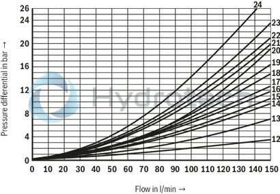
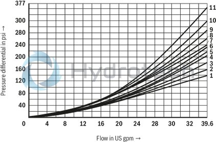
(measured with HLP46, ϑOil = 40 ±5 °C)
Δp-qV characteristic curves

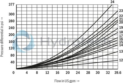
|
Symbol |
Direction of flow |
|||
|
P ‒ A |
P ‒ B |
A ‒ T |
B ‒ T |
|
|
A; B |
6 |
6 |
‒ |
‒ |
|
C |
1 |
2 |
5 |
7 |
|
D |
2 |
2 |
5 |
7 |
|
E |
17 |
16 |
19 |
21 |
|
F |
2 |
3 |
22 |
23 |
|
G |
4 |
4 |
24 |
24 |
|
H |
14 |
14 |
20 |
21 |
|
J |
3 |
3 |
9 |
11 |
|
J73 |
22 |
21 |
23 |
24 |
|
L |
3 |
3 |
9 |
9 |
|
M |
14 |
14 |
6 |
8 |
|
P |
17 |
14 |
20 |
23 |
|
Q |
16 |
17 |
4 |
8 |
|
R |
18 |
21 |
18 |
24 |
|
T |
18 |
4 |
10 |
24 |
|
U |
3 |
3 |
6 |
11 |
|
V |
17 |
17 |
18 |
20 |
|
W |
upon request |
|||
|
Central position: |
|||||
|
Symbol |
Direction of flow |
||||
|
P ‒ A |
P ‒ B |
B ‒ T |
A ‒ T |
P ‒ T |
|
|
H |
12 |
12 |
13 |
13 |
15 |
Performance limits
(measured with HLP46, ϑOil = 40 ±5 °C)
Notice!
The specified performance limits are valid for use with two directions of flow (e. g. from P to A and simultaneous return flow from B to T).
Due to the flow forces acting within the valves, the admissible performance limit may be considerably lower with only one direction of flow (e. g. from P to A while port B is blocked)!
In such use cases, please consult us!
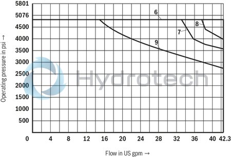
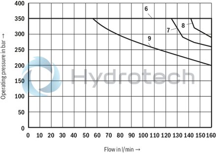
|
Characteristic curve |
Symbol |
|
6 |
C, C/OF, D, D/OF, E, J, L, M, U |
|
7 |
H |
|
8 |
G |
|
9 |
A,B |
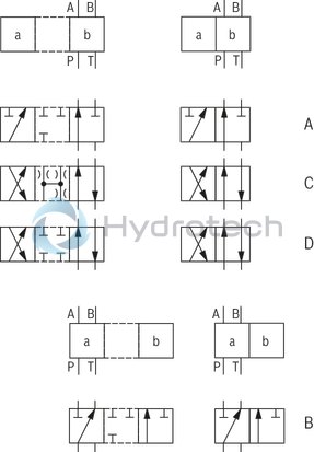
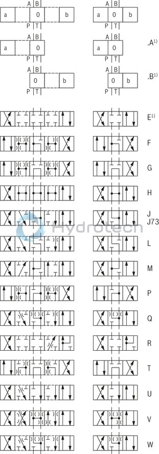
| 1) | Example:Symbol E with spool position “a” → ordering code ..EA..Symbol E with spool position “b" → ordering code ..EB.. |
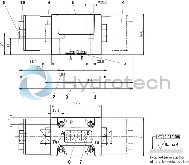
Dimensions in mm
3/2 directional seat valve
Dimensions in mm
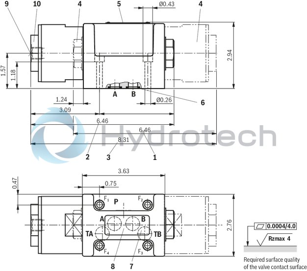
Notices!
Deviating from ISO 4401, port T is referred to as TA and port T1 is referred to as TB in this data sheet. The dimensions are nominal dimensions which are subject to tolerances. When screwing in/releasing the connection tube on the pilot oil port (9), the bushing (10) must be secured against twisting by using an open-end wrench.Subplates according to data sheet 45054 (separate order)
G 66/01 (G3/8) 1)
G 67/01 (G1/2) 1)
G 534/01 (G3/4) 1)
G 66/12 (SAE-6; 9/16-18) 2)
G 67/12 (SAE-8; 3/4-16) 2)
G 534/12 (SAE-12; 1-1/16-12) 2)
Valve mounting screws (separate order)
4 hexagon socket head cap screws, metric
ISO 4762 - M6 x 40 - 10.9-flZn-240h-L
(friction coefficient μtotal = 0.09 to 0.14);
tightening torque MA = 12.5 Nm ± 10 %,
material no. R913000058
or
4 hexagon socket head cap screws
ISO 4762 - M6 x 40 - 10.9 (self procurement)
(friction coefficient μtotal = 0.12 to 0.17);
tightening torque MA = 15.5 Nm ± 10 %
4 hexagon socket head cap screws UNC
1/4-20 UNC x 1-1/2” ASTM-A574
(friction coefficient μtotal = 0.19 to 0.24);
tightening torque MA = 25 Nm ± 15 %,
(friction coefficient μtotal = 0.12 to 0.17);
tightening torque MA = 19 Nm ± 10 %,
material no. R978800710
With different friction coefficients, the tightening torques are to be adjusted accordingly!