
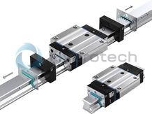
BOSCH REXROTH
R18515222A
BOSCH REXROTH
MATERIAL: R18515222A
SUMMARY:
Quantity in stock: 0
Load capacities and load moments
|
Size |
25 | 35 | 45 | 55 | 65 | ||
|
C |
N |

|
30300 | 61000 | 106600 | 140400 | 237200 |
|
C0 |
N |
59500 | 119400 | 209400 | 284700 | 456300 | |
|
Mt |
Nm |

|
390 | 1210 | 2640 | 4120 | 8430 |
|
Mt0 |
Nm |
770 | 2370 | 5180 | 8350 | 16210 | |
|
ML |
Nm |

|
300 | 760 | 1650 | 2610 | 5260 |
|
ML0 |
Nm |
580 | 1480 | 3240 | 5290 | 10120 | |
| Determination of the dynamic load ratings and load moments is based on a 100,000 m stroke in accordance with DIN ISO 14728-1. Often only 50,000 m are actually stipulated. For comparison: Multiply values C, Mt, and ML from the table by 1.23. | |
General technical data
|
Size |
25 | 35 | 45 | 55 | 65 | |
|
amax 1) |
m/s² |
150 | ||||
|
vmax |
m/s |
4 | ||||
|
m |
kg |
0.73 | 2.15 | 4.05 | 5.44 | 10.72 |
|
FR 2) |
N |
30 | 40 | 60 | 70 | 90 |
|
μ 3) |
0.0004 ... 0.001 | |||||
|
Material |
CS | |||||
|
Operating conditions |
||||||
|
Size |
25 | 35 | 45 | 55 | 65 | |
|
Permissible ambient temperature (min ... max) 4) |
-10 °C ... +80 °C | |||||
| 1) | Prerequisite: There must be preload, even during operation under load. |
| 2) | Guideline value for frictional drags of the complete, sealed and lubricated roller runner blocks. |
| 3) | Without friction of seal |
| 4) | Brief peaks up to 100 °C are permitted. For even lower sub-zero temperatures, please consult us. |
Legend
|
Symbol |
Description |
Unit |
|
amax |
Maximum acceleration travel |
m/s2 |
|
C |
Dynamic load capacity |
N |
|
C0 |
Static load capacity |
N |
|
Fpr |
Preload force |
N |
|
FR |
Friction force |
N |
|
m |
Mass |
kg |
|
ML |
Dynamic longitudinal moment load capacity |
Nm |
|
ML0 |
Static longitudinal moment load capacity |
Nm |
|
Mt |
Dynamic torsional moment load capacity |
Nm |
|
Mt0 |
Static torsional moment laod capacity |
Nm |
|
vmax |
Maximum permissible speed |
m/s |
|
μ |
Friction coefficient |
General technical data and calculations
Accuracy classes
Definition of preload class
The preload class is the pre-tensioning force Fpr based on the dynamic load rating C of the particular roller runner block.
Selection of the preload class
|
Code |
Application area |
|
C1 |
Special version on request |
|
C4 |
|
|
C5 |
|
|
C2 |
For precise guide systems with both high external loading and high demands on overall rigidity;also recommended for single rail systems. |
|
Above average moment loads can be absorbed without significant elastic deflection. |
|
|
Further improved overall rigidity with only medium moment loads. |
|
|
C3 |
For highly rigid guide systems such as precision machine tools, etc. |
|
Above average loads and moments can be absorbed with the least possible elastic deflection. |
|
|
Roller runner blocks with preload C3 available in accuracy classes P, SP (GP) and UP only. |
Recommended combination based on preload and accuracy class
Recommendation for preload C2: Accuracy classes H and P
Recommendation for preload C3: Accuracy classes P and SP (GP)
Combination of hard chrome plated roller runner blocks with hard chrome plated roller guide rails
Upon combination of hard chrome plated roller runner blocks with preload C2 or C3 and hard chrome plated roller guide rails, the preload increases by approx. half a preload class.
Preload force Fpr (N)
|
Roller Runner Blocks |
Size |
25 |
35 |
45 |
55 |
65 |
100 |
125 |
55/85 |
65/100 |
||
|
|
Type |
Design type |
Preload class |
Preload force Fpr (N) |
||||||||
|
Roller runner block, steel1) Roller runner block, Resist CR2) |
R1851 R1822 R1821 R1861 |
FNS SNS SNH |
C1 |
830 |
1680 |
2930 |
3860 |
6520 |
‒ |
‒ |
‒ |
‒ |
|
C2 |
2240 |
4510 |
7890 |
10400 |
17600 |
36900 |
60600 |
‒ |
‒ |
|||
|
C3 |
3640 |
7320 |
12800 |
16800 |
28500 |
59900 |
98400 |
‒ |
‒ |
|||
|
C4 |
4770 |
9610 |
16800 |
22100 |
37400 |
‒ |
‒ |
‒ |
‒ |
|||
|
C5 |
5610 |
11300 |
19700 |
26000 |
43900 |
‒ |
‒ |
‒ |
‒ |
|||
|
R1853 R1823 R1824 R1863 |
FLS SLS SLH |
C1 |
1010 |
2060 |
3640 |
4790 |
8140 |
‒ |
‒ |
‒ |
‒ |
|
|
C2 |
2720 |
5540 |
9790 |
12900 |
21900 |
50600 |
81600 |
‒ |
‒ |
|||
|
C3 |
4420 |
8990 |
15900 |
20900 |
35500 |
82200 |
132600 |
‒ |
‒ |
|||
|
C4 |
5800 |
11800 |
20800 |
27400 |
46600 |
‒ |
‒ |
‒ |
‒ |
|||
|
C5 |
6810 |
13900 |
24500 |
32200 |
54700 |
‒ |
‒ |
‒ |
‒ |
|||
|
R1854 |
FXS |
C2 |
‒ |
‒ |
‒ |
‒ |
29300 |
‒ |
‒ |
‒ |
‒ |
|
|
C3 |
‒ |
‒ |
‒ |
‒ |
47700 |
‒ |
‒ |
‒ |
‒ |
|||
|
Wide roller runner block, steel1) Wide roller runner block, Resist CR2) |
R1872 |
BLS |
C2 |
‒ |
‒ |
‒ |
‒ |
‒ |
‒ |
‒ |
13200 |
21200 |
|
C3 |
‒ |
‒ |
‒ |
‒ |
‒ |
‒ |
‒ |
21500 |
34500 |
|||
| 1) | All steel parts made of carbon steel |
| 2) | Steel roller runner block body with corrosion-resistant coating, matt silver finish, hard chrome-plated |
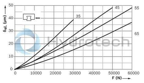
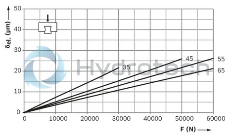
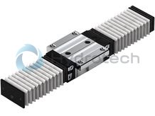
Rigidity of roller rail system for preload C2
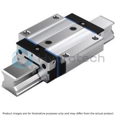
Standard roller runner block FNS R1851
Roller runner block mounted with 6 screws:
Externally with 4 screws of strength class 12.9
In the middle with 2 screws of strength class 8.8
Preload class
C2 = Preload (in accordance with table for pre-tensioning force Fpr in section "Technical information")
Down load

| 1) | δel. = elastic deformation μm |
| 2) | F = load N |
lift-off load

| 1) | δel. = elastic deformation μm |
| 2) | F = load N |
side load
| 1) | δel. = elastic deformation μm |
| 2) | F = load N |
Rigidity of roller rail system for preload C3
Standard roller runner block FNS R1851
Roller runner block mounted with 6 screws:
Externally with 4 screws of strength class 12.9
In the middle with 2 screws of strength class 8.8
Preload class
C3 = Preload (in accordance with table for pre-tensioning force Fpr in section "Technical information")
Down load
| 1) | δel. = elastic deformation μm |
| 2) | F = load N |
lift-off load

| 1) | δel. = elastic deformation μm |
| 2) | F = load N |
side load

| 1) | δel. = elastic deformation μm |
| 2) | F = load N |

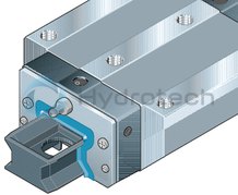
| a) | For O-ring: Size 25: Ø 5 • 1.5 (mm), sizes 30 to 65: Ø 7 • 1.5 (mm). Open lube port if necessary (see lubricating and mounting instructions). |
| b) | Recommended position for pin holes (E4 dimensions, see lubricating and mounting instructions). Pre-drilled holes may be present at this position for manufacturing reasons. These may be bored open. |
| c) | Lube nipple, thread M6 – 8 deep: Connection is possible on all sides (only at front for size 25). Dimensions differ among different connection pieces. See "Accessories" for more information about lube ports. |
| d) | For Roller Guide Rails of accuracy class H, this base area may be without a groove for manufacturing reasons. |
| e) | Sealing plugs may be present at this position for manufacturing reasons. Remove these prior to mounting. |
| f) | Size 65 |
Dimensions
|
Size |
25 | 35 | 45 | 55 | 65 | |
|
A |
mm |
70 | 100 | 120 | 140 | 170 |
|
A1 |
mm |
35 | 50 | 60 | 70 | 85 |
|
A2 |
mm |
23 | 34 | 45 | 53 | 63 |
|
A3 |
mm |
23.5 | 33 | 37.5 | 43.5 | 53.5 |
|
B |
mm |
97 | 118 | 147 | 170.65 | 207.3 |
|
B1 |
mm |
63.5 | 79.6 | 101.5 | 123.1 | 146 |
|
E1 |
mm |
57 | 82 | 100 | 116 | 142 |
|
E2 |
mm |
45 | 62 | 80 | 95 | 110 |
|
E3 |
mm |
40 | 52 | 60 | 70 | 82 |
|
E4 |
mm |
55 | 80 | 98 | 114 | 140 |
|
E8 |
mm |
33.4 | 50.3 | 62.9 | 74.2 | 35 |
|
E8.1 |
mm |
- | 93 | |||
|
E8.2 |
mm |
40.2 | 60.5 | 72 | 81.6 | 106 |
|
E9 |
mm |
8.3 | 13.1 | 16.7 | 18.85 | 9.3 |
|
E9.1 |
mm |
- | 26 | |||
|
E9.2 |
mm |
21.4 | 29.1 | 36.5 | 40.75 | 55 |
|
H |
mm |
36 | 48 | 60 | 70 | 90 |
|
H1 |
mm |
30 | 41 | 51 | 58 | 76 |
|
Dimension H2 with cover strip |
mm |
23.6 | 31.1 | 39.1 | 47.85 | 58.15 |
|
Dimension H2 without cover strip |
mm |
23.4 | 30.8 | 38.8 | 47.55 | 57.85 |
|
K1 |
mm |
14.05 | 15.55 | 17.45 | 21.75 | 30 |
|
K2 |
mm |
- | 17.4 | 20.35 | 24.9 | 33 |
|
N1 |
mm |
9 | 12 | 15 | 18 | 23 |
|
N2 |
mm |
7.3 | 11 | 13.5 | 13.7 | 21.5 |
|
N5 |
mm |
5.5 | 7 | 8 | 9 | 9.3 |
|
N6 |
14.3 mm ±0.5 | 19.4 mm ±0.5 | 22.4 mm ±0.5 | 28.7 mm ±0.5 | 36.5 mm ±0.5 | |
|
ØS1 |
mm |
6,7 | 8,5 | 10,4 | 12,4 | 14,6 |
|
S2 |
M8 | M10 | M12 | M14 | M16 | |
|
ØS5 |
mm |
7 | 9 | 14 | 16 | 18 |
|
S9 1) |
M3 ‒ 6.5 mm deep | M3 ‒ 6 mm deep | M4 ‒ 9 mm deep | M5 ‒ 8 mm deep | M4 ‒ 8 mm deep | |
|
T2 2) |
mm |
30 | 40 | 52.5 | 60 | 75 |
|
V1 |
mm |
7.5 | 8 | 10 | 12 | 15 |
| 1) | Thread for adjoining parts |
| 2) | Dimension T2 = hole spacing in the roller guide rail |
Scraper plates for Roller Rail Systems RSHP
R1820 .1. 3. / R1810 291 40
Scraper plates for Roller Rail Systems RSHP
R1820 .1. 3. / R1810 291 40
For mounting on Roller Runner Blocks for Roller Guide Rails with cover strip Material: Corrosion-resistant spring steel as per DIN EN 10088 Design: brightMounting of a scraper plate with scraping function on Roller Runner Block (video)
Mounting of a scraper plate (video)
Service
FKM seals for Roller Rail Systems
R1810 .2. 3.

FKM seals for Roller Rail Systems
R1810 .2. 3.
For mounting on Roller Runner Blocks for all Roller Guide Rails Two-piece FKM seal Material: Stainless steel plus FKM seal Simple assembly/removal on fixed roller guide rail Observe the mounting instructionsInstructions
Mounting of FKM-Seals (Video)
Service
FKM seals set for Roller Rail Systems
R1810 .2. 7.

FKM seals set for Roller Rail Systems
R1810 .2. 7.
For mounting on Roller Runner Blocks for all Roller Guide RailsInstructions
Mounting of FKM-Seal and Scraper Plate (Set) (Video)
Service
Front lube units
R1810 .25 00
Front lube units
R1810 .25 00
Front lube units suitable for RSHP Roller Runner Blocks and generation 1 Roller Runner Blocks For travel up to 5,000 km without relubrication Roller runner block only needs initial lubrication with grease Front lube units on both sides of the roller runner block Low lubricant lossCAD data
Mounting of Front Lubrication Unit (Video)
Service
Hydraulic-type lube nipple according to DIN 71412 Form A
R3417 0.. 02
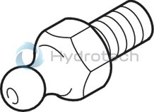
Hydraulic-type lube nipple according to DIN 71412 Form A
R3417 0.. 02
CAD data
Service
Hydraulic-type lube nipple according to DIN 71412 30°
R3417 023 02
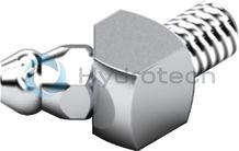
Hydraulic-type lube nipple according to DIN 71412 30°
R3417 023 02
Service
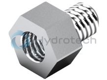
Hydraulic-type lube nipple according to DIN 71412 45°
R3417 007 02
Hydraulic-type lube nipple according to DIN 71412 45°
R3417 007 02
CAD data
Service
Reducer M6
R3455 032 04
Reducer M6
R3455 032 04
Service
Extension M6
R3455 03. 04
Extension M6
R3455 03. 04
Service
Connector for tube Ø 2.5 mm
R3455 0.. ..
Connector for tube Ø 2.5 mm
R3455 0.. ..
CAD data
Service
Connector for tube Ø 4 mm
R3455 0.. ..
Connector for tube Ø 4 mm
R3455 0.. ..
CAD data
Service
Swivel fittings L = 22 mm
R3417 0.. 09
Swivel fittings L = 22 mm
R3417 0.. 09
CAD data
Service
Swivel fittings L = 12 mm
R3417 0.. 09
Swivel fittings L = 12 mm
R3417 0.. 09
Service
Straight connectors for Roller Rail Systems
R3417 03. 09
Straight connectors for Roller Rail Systems
R3417 03. 09
Push-in fittings for tubesCAD data
Service
Elbow plug-in connections, rotatable for Roller Rail Systems
R3417 03. 09
Elbow plug-in connections, rotatable for Roller Rail Systems
R3417 03. 09
Push-in fittings for tubesCAD data
Service
O-rings
R3411 ... 01

O-rings
R3411 ... 01
Service
Standard bellows
R1..0 .0. 00
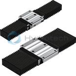
Standard bellows
R1..0 .0. 00
Material: Polyurethane-coated polyester fabricService
Heat-resistant bellows
R1..0 .5. 00
Heat-resistant bellows
R1..0 .5. 00
Material: Nomex fabric, metalized on both sides Temperature stability Non combustible, non flammable Resistant to sparks, welding spatter and hot chips.Service
Transport locks for Roller Runner Blocks
Transport locks for Roller Runner Blocks
For transporting and as a mounting aid Material: PlasticService