
BOSCH REXROTH
R117100720
BOSCH REXROTH
MATERIAL: R117100720
SUMMARY:
Quantity in stock: 0
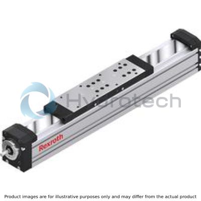
The new product generation 3 (MKX-XXX-NN-3) of the Rexroth Linear Modules is based on the consistent further development of the previous series. The usual Rexroth performance features have been improved once again with consideration of backward compatibility.
Rexroth Linear Modules of product generation 2 (MKX-XXX-NN-2) are precise, ready-to-install guide systems with high-performance features in compact dimensions.
Product description MKK-xxx-NN-3
Structural design
Ready-to-install Linear Modules in any length up to Lmax Extremely compact aluminum profile with integrated Rexroth Ball Rail Systems Carriages made of aluminum with T-slots or threaded holes and with centering holes in each case Individual lubrication versions for connection to one-point lubrication systems Driven by precision Ball Screw Assembly (BASA) in rolled design, optionally in tolerance grade T7 or T5 according to ISO 3408-3 with clearance-free Cylindrical Single Nut Sealing strip (plastic cover strip for MKK-065, corrosion-resistant steel strip for MKK-080 and MKK-110)
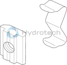
Attachments (accessories program)
Sensors and extension cables Switch (proximity or mechanical) Switching lug Socket and plug Cable duct made of aluminum profile Clamping fixtures and sliding blocks Connecting shafts Connection technology for Linear Motion Systems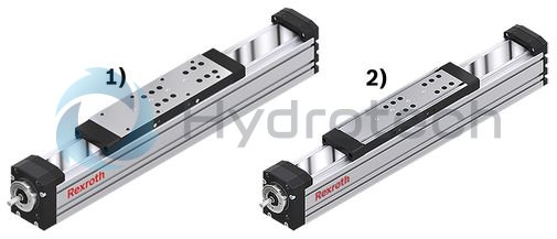
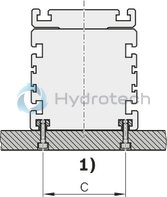
| 1) | Carriage with thread |
| 2) | Carriage with T-slots |
Screw support (SPU) for MKK-080-NN-3 and MKK-110-NN-3
The screw support SPU provides the following benefits:
Screw support for horizontal applications (vertical applications in preparation) Screw support can be selected as standard option via the option number. A maximum of 2 screw support pairs is possible. High speed over long lengths of up to 5400 mm. Guideway of the screw supports in the frame. Screw supports are maintenance-free. Screw supports are protected by optionally selectable sealing strip.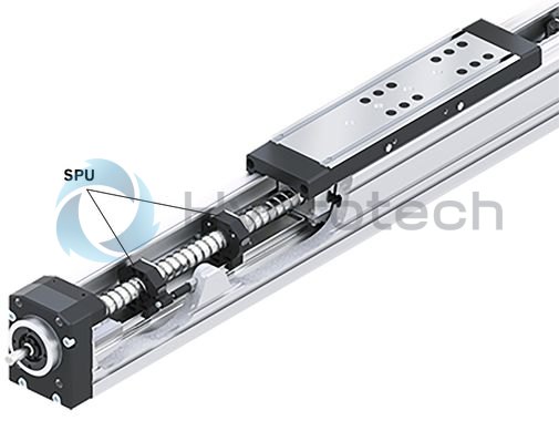
Integrated Measuring System
The IMS-A measuring system offers the following advantages:
No additional space required. No external mounting surfaces required for the measuring system. No measurement inaccuracies due to parallelism offset between the measuring system and the guide system. Full integration of the measuring system components into the guide means no complex mounting or tuning work is needed. The Runner Block, Scanner and Guide Rail with scale can be replaced individually during servicing. Interfaces: HIPERFACHE or DRICE-CLiQ. Connecting cable directly on the side of the carriage.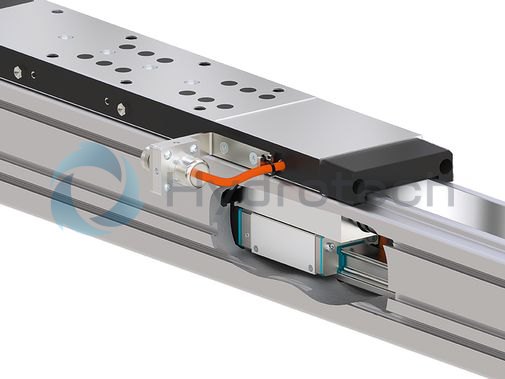
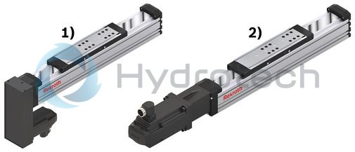
| 1) | Motor mounting with timing belt side drive |
| 2) | Motor mounting with flanged-type coupling |
Material pairing
ALST:
Frame, carriage and end blocks made of anodized aluminum (AL) Ball Guide Rail, Ball Runner Block and Ball Screw Assembly made of antifriction bearing steel (ST) Angular-contact ball bearing and deep-groove ball bearing of the Screw Drive bearing structure made of antifriction bearing steel
ALCR:
Frame, carriage and end blocks made of anodized aluminum (AL) Ball Guide Rail and Ball Screw Assembly made of antifriction bearing steel with corrosion-resistant coating, matte-silver finish, hard chrome plated (Resist CR). Ball Runner Block made of corrosion-resistant steel (Resist NR) Angular-contact ball bearing and deep-groove ball bearing of the Screw Drive bearing structure made of antifriction bearing steelLubrication variants
LSS: (Initial lubrication done at the factory)
MKK-065, MKK-080, MKK-110:
Grease lubricant Dynalub 510, NLGI grade 2 lithium-based high-performance grease according to DIN 51818 (KP2K-20 according to DIN 51825) Initial standard greasing done at the factory, suitable for normal environmental conditions. Simple relubrication via manual grease gun.
LPG: (Corrosion prevention, no initial lubrication)
Linear Module without initial greasing done at the factory. Ball Rail System and ball screw drive only with corrosion prevention. Basic lubrication required
LCF: (prepared for connection to central lubrication systems with liquid grease)
for liquid grease, NLGI grade 00 lithium-based high-performance grease according to DIN 51818 (GP00K-20 according to DIN 51826) Only use liquid grease lubrication with single-line total-loss lubrication systems via piston distributors. Basic lubrication required
LCO: (prepared for connection to central lubrication systems with oil)
Ball Runner Block and ball screw drive nut with integrated non-return valves Only use oil lubrication with single-line total-loss lubrication systems via piston distributors. Basic lubrication requiredProduct description MKK-xxx-NN-2
Rexroth Linear Modules with Ball Rail System and Ball Screw Assembly for high positioning accuracy and repeatability as well as high thrust forces.
Structural design
Ready-to-install Linear Modules in any length up to Lmax Extremely compact aluminum profile with integrated Rexroth Ball Rail Systems Drive via Rexroth Ball Screw Assembly set to zero-clearance (also available without a drive) Carriages made of aluminum, with T-slots or threaded holes (depending on the size) Cover by: Plastic strip for MKK-040 and bellows for MKK-165
Attachments
Switch (proximity or mechanical) Socket and plug Cable duct made of aluminum profile
Attachments (accessories program)
Clamping fixtures and sliding blocks Connecting shafts Connection technology for Linear Motion Systems Sensors and extension cables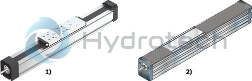
| 1) | MKK-040 with sealing strip |
| 2) | MKK-165 with bellows |
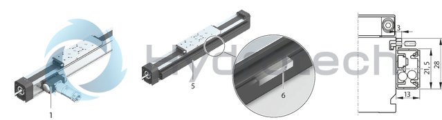
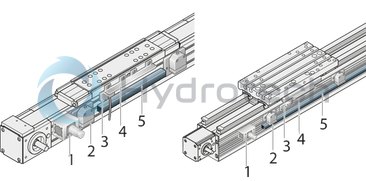
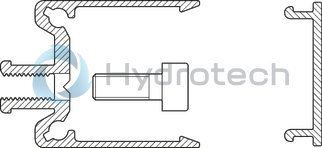
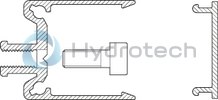
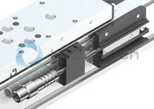
Structure and attachments
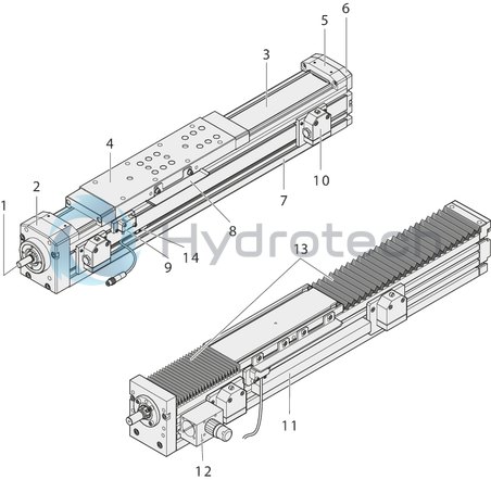
Structural design
1 Rexroth Ball Screw Assembly (BASA) with backlash-free, cylindrical single nut
2 End block fixed bearing
3 Sealing strip for MKK-065, MKK-080, MKK-110
4 Carriage with runner block
5 Strip fixing
6 End plate floating bearing
7 Frame
Attachments
8 Switching cam
9 Proximity switch
10 Mechanical switch
11 Cable duct
12 Socket/plug
13 Bellows cover for MKK-165
14 Magnetic field sensor
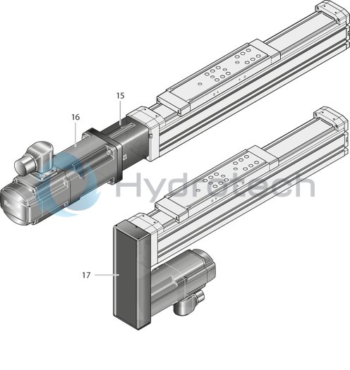
15 Mount
16 Servo motor
17 Timing belt side drive
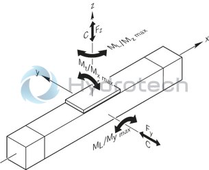
Maximum values for each size
|
Size |
MKK-040-NN-2 | MKK-065-NN-3 | MKK-080-NN-3 | MKK-110-NN-3 | MKK-165-NN-2 | |
|
C |
N |
3750 | 16000 | 38000 | 46500 | 84100 |
|
Cbs |
N |
4100 | 13320 | 15480 | 34200 | 54000 |
|
Cfb |
N |
4000 | 13400 | 16900 | 26000 | 29000 |
|
Mt |
Nm |
22.3 | 154 | 487 | 666 | 1803 |
|
ML |
Nm |
93.8 | 533 | 1843 | 2235 | 5130 |
|
Mx max |
Nm |
11 | 62 | 195 | 264 | 723 |
|
My max |
Nm |
47 | 213 | 737 | 894 | 2085 |
|
Mz max |
Nm |
47 | 213 | 737 | 894 | 2085 |
|
Fy max |
N |
1875 | 6400 | 15200 | 18600 | 34100 |
|
Fz1 max |
N |
1875 | 6400 | 15200 | 18600 | 34100 |
|
Fz2 max |
N |
1875 | 6400 | 15200 | 18600 | 34100 |
|
Lmax |
mm |
1000 | 2500 | 3400 | 5400 | 4000 |
|
amax |
m/s² |
50 | ||||
|
vmax |
m/s |
1 | 1.21 | 2.5 | 1.6 | 1.47 |
| Maximum values depends on the selected configuration. |
Legend
|
Symbol |
Description |
Unit |
|
C |
Dynamic load capacity, linear guide |
N |
|
Cbs |
Dynamic load capacity, ball screw drive |
N |
|
Cfb |
Dynamic load capacity, fixed bearing |
N |
|
Mt |
Dynamic torsional moment load capacity |
Nm |
|
ML |
Dynamic longitudinal moment load capacity |
Nm |
|
Mx max |
Maximum admissible torsional moment around the x-axis |
Nm |
|
My max |
Maximum admissible torsional moment around the y-axis |
Nm |
|
Mz max |
Maximum admissible torsional moment around the z-axis |
Nm |
|
Fy max |
Maximum dynamic load in y-direction |
N |
|
Fz1 max |
Maximum dynamic load in z-direction |
N |
|
Fz2 max |
Maximum dynamic load in z-direction |
N |
|
Lmax |
Maximum length |
mm |
|
amax |
Maximum acceleration travel |
m/s2 |
|
vmax |
Maximum permissible speed |
m/s |
Mounting
General information
The linear modules are mounted using various fastening elements:
Clamping fixtures Sliding blocks for size -110 and up Square nuts Spring nuts Screws for T-slots as per DIN 787 (no picture).Length depends on base.
When mounting Linear Modules, please note the maximum tightening torques listed in the table.
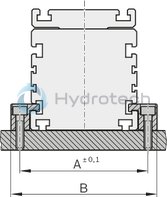
Mounting with clamping fixtures
Mounting with sliding blocks
| 1) | 85 (size .. -110) 120 (size -165) |
|
Size |
A |
B |
|
(mm) |
(mm) |
|
|
-040 |
52,2 |
65,5 |
|
-065 |
81,0 |
95,0 |
|
-080 |
96,0 |
110,0 |
|
-110 |
132,0 |
150,0 |
|
-165 |
192,0 |
218,0 |
|
-145 |
172,0 |
198,0 |
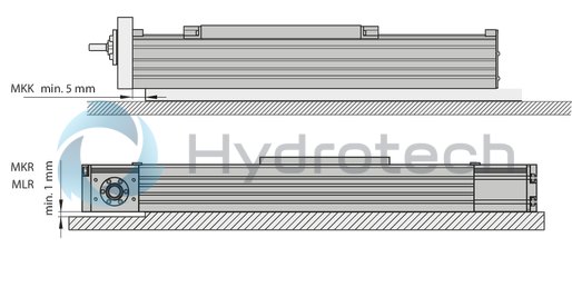
Do not support the linear module on end enclosures, end blocks or on end plates!
The frame is the load-bearing part!
Tightening torques of fastening screws
with friction factor 0.125 strength class 8.8

|
8.8 |
M4 |
M5 |
M6 |
M8 |
M10 |
M12 |

|
(Nm) |
2,7 |
5,5 |
9,5 |
23 |
46 |
80 |
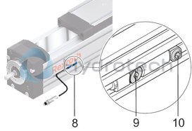
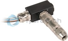
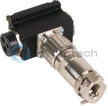
Switching system overview
1 Socket and plug
2 Mechanical switch with attachments
3 Proximity switch
4 Switching cam
5 Mounting duct/cable duct
6 Magnetic field sensor with fixed potted cable
(Reed/Hall sensor (for fastening duct))
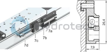
7 Reed/Hall sensor with plug and sensor mount
7a: Sensor (Hall sensor option 59 or reed sensor option 58)
7b: Sensor mount including set screws (loose) and square nut
7c: Cable holders (3 pieces) including set screw (loose)
7d: Plug
8 Magnetic switch
9 Clamping screw
10 Sliding block
Switch mounting arrangement MKK/MKR-040-NN-2
Switch mounting arrangement with magnetic field sensor and mounting duct
The switch activator is a magnet that is built into the carriage (no switching cam necessary). The switch activation points can be positioned anywhere along the stroke.
Version: Hall sensor (PNP NC) or reed sensor (change-over contact)
Notes for mounting:
The magnetic field sensors are pushed into the top T-slot in the cable duct and fixed with set screws. The cables are routed along the side of the T-slot for switches.
Switch mounting with magnetic field sensor, connector and sensor mount
Sensor mounting kit
The switch activator is a magnet that is integrated in the carriage (no switching angle needed). The switching positions can be freely configured via the stroke.
General mounting instructions:
The sensor mounting is only permitted on one side of the linear module (right or left) and is only done after the linear module has been attached to the mounting base. For a description of the mounting and determination of the switching positions, see the instruction manual for the linear modules. See "Accessories" section for technical data
Switch mounting MKK/MKR/MLR-xxx-NN-x
MKK/MKR-xxx-NN-3
MKK/MKR/MLR-xxx-NN-x
Socket and plug, cable duct
Attach the socket to the side with the most switches. The socket and plug are not pre-wired. The variable sliding attachment allows switching positions to be optimized during start-up. The plug can be mounted in three directions.
Cable duct
The cable duct is fastened in the T-slots on the side of the frame. Fastening screws widen the profile and ensure that the cable duct is securely mounted.
See the illustration for the position of the slot.
The cable duct will accommodate up to two cables for mechanical switches and three cables for proximity switches.
Fastening screws and cable grommets are included.
Mounting examples of switches
Determination of the switching position
Switching distance: The switching distance is the distance between the carriage center (TM) and the zero point (0) when a switch is actuated (indicated in mm). Example of a mechanical limit switch (assuming the zero point is at L/2):
Maximum switching distance = 0.5 x (max. travel distance) – excess travel = 0.5 x effective stroke
For safe operation of the linear module the excess travel must be greater than the braking path.
For MKR... and MLR...: The acceleration travel sa can be assumed as the reference value for the braking distance.
For MKK...: In most cases, the following is sufficient as a guideline value for the excess travel (braking path): Excess travel = 2 x screw lead P.
Note the smallest possible switching distance (determined by attachments):
mechanical-mechanical = 60 mm; mechanical-proximity = 45 mm; proximity-proximity = 28 mm.
for MKR-145: mechanical-mechanical = 62 mm; mechanical-proximity = 49 mm; proximity-proximity = 35 mm
The switches as well as socket with plug are fixed in the upper T-slots of the frame and actuated by a switch tab on the carriage.
Mounting side of the switches:
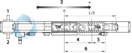
| 1) | links (L) |
| 2) | right (R) |
| 3) | Direction of travel |
| 4) | 0.5 x stroke |
| 5) | Excess travel |
| 6) | 0.5 x max. travel path |
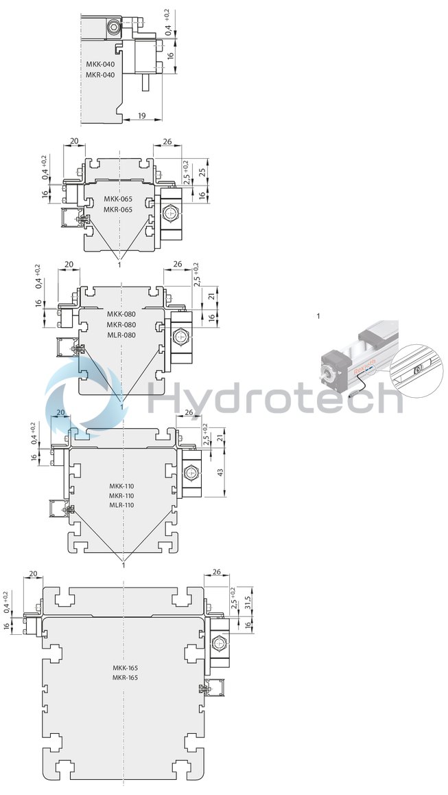
| 1) | Sensor slot MKK/MKR-xxx-NN-3 |
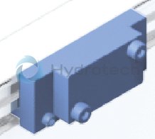
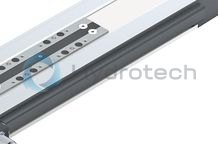
Clamping fixtures for Linear Modules
Clamping fixtures for Linear Modules
CAD data
Service
Sliding blocks and springs for Linear Modules
Sliding blocks and springs for Linear Modules
CAD data
Service
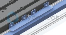
Anchor strips for Linear Modules

Anchor strips for Linear Modules
Steel, black finished All anchor strips can be fixed for a vertical installation positionCAD data
Service
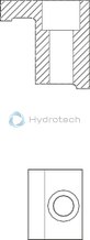
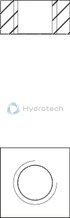
Centering rings for Linear Modules
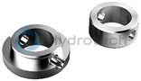
Centering rings for Linear Modules
CAD data
Service
Square nuts for Linear Modules
Square nuts for Linear Modules
CAD data
Service
Cable duct
Cable duct
Service
CAD data
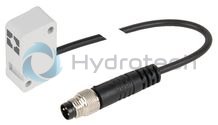
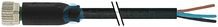
Magnetic sensor with free line end
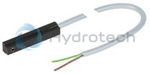
Magnetic sensor with free line end
Service
CAD data
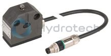
Magnetic sensor with M8x1 plug
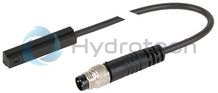
Magnetic sensor with M8x1 plug
Service
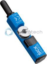
Magnetic sensor with plug and sensor mount
Magnetic sensor with plug and sensor mount
Service
Proximity sensor with free line end
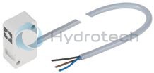
Proximity sensor with free line end
Service
CAD data
Proximity sensor with M8x1 plug
Proximity sensor with M8x1 plug
Service
Additional components for inductive sensor
Additional components for inductive sensor
Service
CAD data
Magnetic sensors
Magnetic sensors
Service
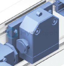
Mechanical switch
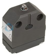
Mechanical switch
Service
CAD data
Mechanical switch with M8x1 plug
Mechanical switch with M8x1 plug
Service
Additional components for mechanical switch
Additional components for mechanical switch
Service
Extension pieces - assembled on one side
Extension pieces - assembled on one side
Service
Adapter
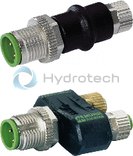
Adapter
Service
Socket and plug
R117560102
Socket and plug
R117560102
Service
Socket and plug
R117500153
Socket and plug
R117500153
Service
Mounting duct
Mounting duct
Mounting and fastening the sensors Cable guideService
Switching angle
Switching angle
Service
CAD data
Required and supplementary documentation
For further instructions and information, please refer to the documentation for this product.
You can find PDF files of these documents on the Internet at www.boschrexroth.com/mediadirectory.
If you are unsure about using this product, please contact Bosch Rexroth.