
BOSCH REXROTH
R911381173
BOSCH REXROTH
MATERIAL: R911381173
SUMMARY:
Quantity in stock: 1
Quantity Details:- Hydrotech Stock: 0 can ship April 29, 2024
- Factory Stock: 1 can ship July 8, 2024
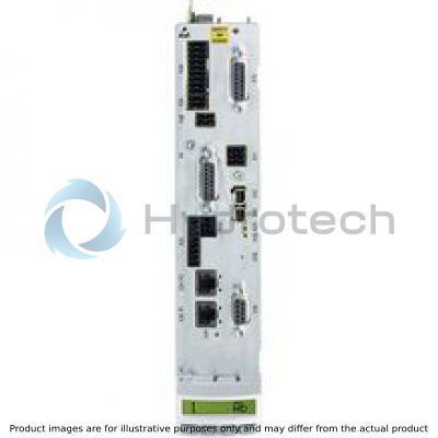
The BASIC single axis control units are suitable for a variety of applications. They support a wide range of control communication and encoder interfaces.
|
01 |
02 |
03 |
04 |
05 |
06 |
07 |
08 |
09 |
10 |
11 |
||||||||
|
CSB |
02 |
. |
- |
- |
- |
- |
- |
- |
- |
|
01 |
IndraDrive - CSB02 |
CSB |
|
02 |
Line |
02 |
|
Variant |
||
|
03 |
1 |
1 |
|
Interface equipment |
||
|
04 |
Basic functionality |
A |
|
Extended functionality |
B |
|
|
Communication |
||
|
05 |
Multi-Ethernet |
ET |
|
Interface 1 |
||
|
06 |
Multi-encoder interface |
EC |
|
Interface 2 |
||
|
07 |
Not equipped |
NN |
|
PROFIBUS |
PB |
|
|
CANopen |
CN |
|
|
Multi-encoder interface |
EC |
|
|
Encoder emulation |
EM |
|
|
Engineering port |
EP |
|
|
Interface 3 (safety technology)1) |
||
|
08 |
Not equipped |
NN |
|
STO (Safe Torque Off) |
L3 |
|
|
Safe Motion2) |
S4 |
|
|
Safe Motion2) |
S5 |
|
|
Safe Motion Bus2) |
SB |
|
|
Interface 4 |
||
|
09 |
Not equipped |
NN |
|
Multi-encoder interface3) |
EC |
|
|
Encoder emulation4) |
EM |
|
|
Digital/analog I/O extension2) |
DA |
|
|
Other version |
||
|
10 |
None |
NN |
|
Firmware |
||
|
11 |
With ADVANCED operating panel, firmware must be ordered separately |
AW |
|
With STANDARD operating panel, firmware must be ordered separately |
FW |
|
|
Without operating panel and firmware |
NW |
|
| 1) | The L3, S4, S5 and SB interfaces ensure both the function and its certification. |
| 2) | Only if interface equipment = B |
| 3) | Only if interface equipment = B and interface 2 = PB, CN or EP |
| 4) | Only if interface equipment = B and interface 2 = PB, CN, EP or EC |
IndraDrive control units
|
Type |
CSB02.1A-ET | CSB02.xB-ET | ||
|
Communication |
||||
|
Multi-Ethernet |
Sercos III, EtherCAT®, PROFINET IO, EtherNet/IP, Powerlink |
● | ● | |
|
Analog interface 1) |
○ | ○ | ||
|
PROFIBUS |
○ | ○ | ||
|
CANopen |
○ | ○ | ||
|
Extensions |
||||
|
Encoder emulation |
○ | ● | ||
|
MultiEncoder interface |
○ | ○ | ||
|
Encoder emulation with level converter function |
○ | ○ | ||
|
Digital/analog I/O extension |
- | ○ | ||
|
Extra engineering port |
○ | - | ||
|
Operating panel |
||||
|
Standard operating panel |
● | ● | ||
|
ADVANCED operating panel with memory card slot |
○ | ○ | ||
|
Cycle times (performance ECONOMY or BASIC/ADVANCED) |
||||
|
Current control 2) |
125/62,5 µs | |||
|
Speed control 2) |
250/125 µs | |||
|
Position control 2) |
500/250 µs | |||
|
PWM frequency |
||||
|
2 kHz 3) |
● | ● | ||
|
4 kHz |
● | ● | ||
|
8 kHz |
● | ● | ||
|
12 kHz 3) |
● | ● | ||
|
16 kHz |
● | ● | ||
|
Inputs/outputs |
||||
|
Digital inputs/of which utilizable as touch probes |
7/2 | 11/2 | ||
|
Digital inputs/outputs (any configurable) |
1 | 5 | ||
|
Analog inputs |
±10 V |
1 | 1 | |
|
±10 V or 0 ... 20 mA |
- | 2 | ||
|
Analog outputs |
±10 V |
- | 2 | |
|
Relay outputs |
1 | 1 | ||
| 1) | Via onboard analog input and optional encoder emulation |
| 2) | ADVANCED performance on BASIC control units can only be used with limitations |
| 3) | Not with ADVANCED performance |
Onboard encoder interface
|
MultiEncoder interface |
Motors (MAD, MAF, MCL, MKE, MS2N, MSK, MSM), Hiperface®, EnDat 2.1, EnDat 2.2, 1 Vss, 5 V TTL, SSI, Resolver |
● | ● |
Safety options according to EN 13849-1 and EN 62061
|
Safe Torque Off |
Category 4 PL e/SIL 3 |
○ | ○ | |
|
Safe Motion |
Category 3 PL d/SIL 2 or category 4 PL e/SIL 3 |
- | ○ | |
|
Safe Motion Bus |
Category 3 PL d/SIL 2 or category 4 PL e/SIL 3 |
- | ○ |
|
Legend |
|
|
● |
Standard |
|
○ |
Option |
|
▼ |
In preparation |
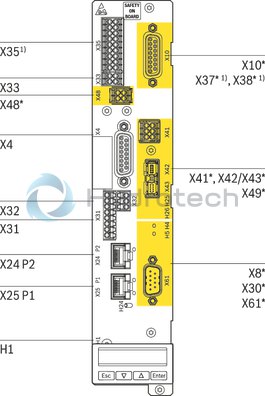
CSB02
|
Front view |
Connection point |
Description |
|
X4 |
Encoder evaluation EC |
|
X8* |
Encoder evaluation EC Encoder emulation EM |
|
|
X10* |
Encoder evaluation EC Encoder emulation EM |
|
|
X24 P2, X25 P1 |
Multi-Ethernet communication ET |
|
|
X30* |
PROFIBUS communication PB |
|
|
X31 |
Digital inputs/outputs Probe input |
|
|
X32 |
Analog inputs |
|
|
X33 |
Voltage input (24 V, 0 V) Standby relay |
|
|
X351) |
Digital inputs/outputs; Analog inputs (current/voltage) Analog outputs (voltage) |
|
|
X37* 1) |
Digital inputs/outputs |
|
|
X38* 1) |
Analog inputs/outputs |
|
|
X41* |
S4, S5, SB safety technology (Not required for SB: X41, X42 and X43; LEDs included) |
|
|
X42/X43* |
||
|
X48* |
Safety Technology (Only available with S4, S5 and SB safety technology) |
|
|
X49* |
L3 safety technology |
|
|
X61* |
Communication CANopen CN |
|
|
H1 |
Operating panel interface |
|
1) CSB02.xB only |
|
* Optional connection points; optional connection points are highlighted in yellow in the figure. |
Motion Control system, based on drive system IndraDrive
MLD
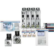
Motion Control system, based on drive system IndraDrive
MLD
Certified safety technology Drive-integrated Motion Control acc. to IEC 61131-3 Electronic synchronization of up to 10 servo-axes Intuitive engineering thanks to the IndraWorks software framework Optional technology and communication interfacesApplication description
Documentation MLD, 13VRS
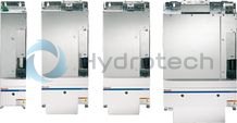
IndraDrive C
HCS02
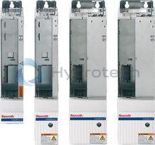
IndraDrive C
HCS02
1.5 kW ... 11 kW power range 12 A ... 70 A maximum current 200 V ... 500 V direct power supply 2.5x overload capacity Compact design for single-axis applicationsOperating instructions
Project planning guide
Project planning guide
Spare parts & repair
CAD Download
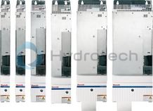
IndraDrive C
HCS03
IndraDrive C
HCS03
22 kW ... 110 kW power range 70 A ... 350 A maximum current 400 V ... 500 V direct power supply 1.5x overload capacity Compact design for single-axis applicationsOperating instructions
Project planning guide
System documentation
Project planning guide
Spare parts & repair
CAD Download
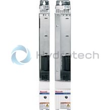
IndraDrive M
HMS01 single-axis inverter
IndraDrive M
HMS01 single-axis inverter
5.5 kW ... 132 kW power range 12.1 A ... 250 A continuous current 12 A ... 350 A maximum current 540 V ... 750 V DC line voltage Protection type IP20Operating instructions
Project planning guide
Project planning guide
Spare parts & repair
CAD Download
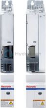
IndraDrive M
HMD01 double-axis inverter
IndraDrive M
HMD01 double-axis inverter
3 kW ... 7.5 kW power range 7 A ... 20 A continuous current 12 A ... 36 A maximum current 540 V ... 750 V DC line voltage Protection type IP20Operating instructions
Project planning guide
Project planning guide
Spare parts & repair
CAD Download
IndraDrive M
HMS02 - single-axis inverter
IndraDrive M
HMS02 - single-axis inverter
5.5 kW ... 11 kW power range 13.8 A ... 25 A continuous current 28 A ... 54 A maximum current 540 V ... 750 V DC line voltage Protection type IP20Operating instructions
Instruction manual
Project planning guide
Spare parts & repair
CAD Download
IndraDrive ML
HMU05 - supply device/inverter
IndraDrive ML
HMU05 - supply device/inverter
Universally usable as supply device or as single-axis inverter 110 kW ... 4 MW power range 380 V ... 690 V mains connection voltage 540 V ... 1100 V DC line voltage Rectifier and regeneration function (when used as supply unit)Project planning guide
Instruction manual
Spare parts & repair
CAD Download
IndraDrive
FWA firmware
IndraDrive
FWA firmware
Comprehensive basic package for implementing most drive tasks Min. 250 µs position controller and bus cycle performance Anti-vibration filter for avoiding vibrations Integrated IEC-compliant Motion Logic Manufacturer-independent Sercos and CANopen CiA 402 device profileApplication description
Application description
Release Notes
Spare parts & repair
CAD Download