

BOSCH REXROTH
R901488640
BOSCH REXROTH
MATERIAL: R901488640
SUMMARY:
Quantity in stock: 0
Ordering code
|
01 |
02 |
03 |
04 |
05 |
06 |
07 |
08 |
09 |
10 |
11 |
12 |
13 |
14 |
15 |
|||||
|
ABSBG |
- |
2X |
/ |
B |
N |
‒ |
/ |
G24 |
V |
/ |
6 |
|
01 |
Accumulator station |
ABSBG |
|
02 |
Component series 20 ... 29 (20 ... 29: unchanged installation and connection dimensions) |
2X |
|
Hydraulic accumulator |
||
|
03 |
Design |
|
|
Bladder-type accumulator according to data sheet 50170 |
B |
|
|
Accumulator volume in l |
||
|
04 |
Bladder-type accumulators |
|
|
1,0 l |
1,0 |
|
|
2,5 l |
2,5 |
|
|
4,0 l |
4,0 |
|
|
6,0 l |
6,0 |
|
|
10 l |
10 |
|
|
20 l |
20 |
|
|
24 l |
24 |
|
|
32 l |
32 |
|
|
50 l |
50 |
|
|
Bladder material |
||
|
05 |
e.g. Acrylonitrile-butadiene rubber (NBR) |
N |
|
Country acceptance for hydraulic accumulator |
||
|
06 |
Short symbol for country acceptance in Europe, Russia and China from the manufacturer's type key |
|
|
Acceptance according to 2014/68/EU by DC |
CE |
|
|
Acceptance according to SELO (China) |
534 |
|
|
Acceptance according to EAC (Russia) |
EAC |
|
|
Operating instructions |
BA |
|
|
Accumulator shut-off block according to data sheet 50131 |
||
|
07 |
ABZSS 10 pressure relief valve 6E |
10 |
|
ABZSS 20 pressure relief valve 10E |
20 |
|
|
ABZSS 30 pressure relief valve 20E |
30 |
|
|
ABZSS 30 SO30 pressure relief valve 30E |
31 |
|
|
Accumulator shut-off block ‒ Unloading |
||
|
08 |
manual and electro-magnetic |
E |
|
manual |
M |
|
|
Accumulator shut-off block ‒ Set pressure at the pressure relief valve |
||
|
09 |
100 bar |
100 |
|
140 bar |
140 |
|
|
210 bar |
210 |
|
|
315 bar |
315 |
|
|
330 bar |
330 |
|
|
Accumulator shut-off block ‒ Voltage type |
||
|
10 |
Direct voltage 24 V |
G24 |
|
Accumulator shut-off block ‒ Seal material |
||
|
11 |
FKM |
V |
|
Mounting construction kit |
||
|
12 |
Mounting with assembly kit A according to DCCS 10060 (console C) |
A |
|
Mounting with clamp according to DCCS 10060 |
B |
|
|
ABZMM pressure gauge according to data sheet 50205 |
||
|
13 |
DN63 |
6 |
|
Pressure gauge scale |
||
|
14 |
bar/MPa |
M |
|
bar/psi |
P |
|
|
Accumulator manufacturer |
||
|
15 |
Bosch Rexroth |
DC |
|
Roth Hydraulics |
RH |
|
|
Order example: ABSBG-2X/B32,0N-CE/30E315G24V/A6MDC |
Accumulators
|
Design |
Bladder-type accumulators | ||
|
Installation position |
Any, preferably with the fluid connection socket at the bottom | ||
|
Ambient temperature range |
°C |
-15 … +65 | |
|
Line connection |
Screw-in thread | ||
|
Hydraulic fluid 1) |
Hydraulic oil according to DIN 51524 | ||
|
Hydraulic fluid temperature range |
NBR bladder |
°C |
-15 … +80 2) |
|
ECO bladder |
°C |
-32 … +80 | |
|
Acceptance specifications |
CE/BA |
Acceptance according to 2014/68/EU or the operating instructions | |
|
China |
SELO | ||
|
Russia |
EAC | ||
| 1) | Other hydraulic fluids upon request. |
| 2) | Others upon request. |
hydraulic, bladder-type accumulator
|
Nominal capacity |
VNenn |
l |
1 | 2.5 | 4 | 10 | 20 | 24 | 32 | 50 |
|
Effective gas volume |
Veff |
l |
1 | 2.4 | 3.7 | 9.2 | 18.1 | 24.5 | 33.4 | 48.7 |
|
Maximum admissible flow |
qmax |
l/min |
240 | 450 | 900 | |||||
|
Maximum admissible operating pressure |
pmax |
bar |
350 | 330 | ||||||
|
Maximum admissible pressure fluctuation range |
Δpdyn |
bar |
200 | 125 | ||||||
pneumatic
|
Charging gas |
Nitrogen, cleanliness class 4.0, N2 = 99.99 vol. % | |||
|
Gas filling pressure |
CE, BA, EAC |
p0 |
bar |
0 |
|
CN |
p0 |
bar |
2 … 5 | |
Shut-off block
|
Seal material |
FKM seals (NBR seals on request) | |
|
Operating temperature range |
°C |
-15 … +80 |
|
Maximum operating pressure |
bar |
350 |
|
Block material |
Steel | |
|
Pressure relief valve, direct controlled |
DBDS…K1X/…VB or DBDS…K1X/…E according to data sheet 25402 | |
|
Cartridge seat valve |
KSDER1PB/HN9V according to data sheet 18136-20 | |
|
Protection class according to VDE 0470-1 ‒ version "K4" |
IP65 | |
|
Voltage type 2) |
V |
24 |
|
Maximum admissible degree of contamination of the hydraulic fluid, cleanliness class according to ISO 4406 (c) |
Class 20/18/15 | |
| 1) | With mating connector mounted and locked |
| 2) | In case of electro-magnetic unloading "E" |
|
Hydraulic fluids |
Classification |
Suitable sealing materials |
Standards |
|
|
Mineral oil |
HL, HLP |
NBR, FKM |
DIN 51524 |
|
|
Fast bio-degradable hydraulic fluids |
Insoluble in water |
HETG |
NBR, FKM |
VDMA 24568 |
|
HEES |
FKM |
|||
|
Soluble in water |
HEPG |
FKM |
VDMA 24568 |
|
| Important information on hydraulic fluids! | |
| For further information and data on the use of other hydraulic fluids, please refer to data sheet 90220 or contact us! | |
| There may be limitations regarding the technical valve data (temperature, pressure range, life cycle, maintenance intervals, etc.)! | |
| The flash point of the hydraulic fluid used must be 40 K higher than the maximum solenoid surface temperature. | |
| Flame-resistant – containing water: Maximum pressure differential per control edge 50 bar. Pressure pre-loading at the tank port > 20 % of the pressure differential; otherwise, increased cavitation. The pressure peaks should not exceed the maximum operating pressures! | |
| Bio-degradable: When using bio-degradable hydraulic fluids that are zinc-solving, zinc may accumulate in the fluid (700 mg zinc per pole tube). |
Pressure gauge
|
Size |
bar |
63 |
|
Pressure gauge |
Glycerin | |
|
Double scale |
bar/MPa | |
Surface treatment:
All steel components and components without protective coating are coated prior to installation (minimum corrosion protection time of 12 h in salt spray test). Then, the devices, components and the piping are installed. All components, assemblies, controls, pipes, fittings and standard parts keep the supplied surface protection and are not additionally coated. The corrosion protection is determined by the least protected element in the assembly.
For applications outside these parameters, please consult us!
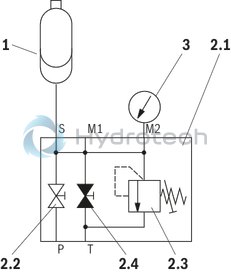
Symbol
Accumulator station with manually operated drain valve
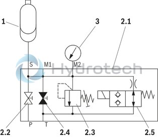
Symbol
Accumulator station with electro-mechanically operated drain valve
|
1 |
Hydraulic accumulator |
|
2.1 |
Accumulator shut-off block with: |
|
2.2 |
System shut-off cock |
|
2.3 |
Pressure relief valve (type-examination tested) |
|
2.4 |
manual unloading |
|
2.5 |
electro-magnetic unloading (only version “E”) |
|
3 |
Pressure gauge with red indication of the maximum admissible operating pressure |
Dimensions: Mounting B with clamp
Accumulator station with 1 l bladder-type accumulator
Dimensions in mm
|
1 |
Hydraulic accumulator |
|
2 |
Clamp |
|
3 |
Shut-off block |
|
4 |
Pressure gauge with red indication of the maximum admissible operating pressure |
|
5 |
Space required for filling device |
|
6 |
Name plate of the accumulator station |
|
7 |
Functional sign (loose) |
|
8 |
Warning sign (loose) |
|
9 |
Threaded connection M8 for equipotential bonding |
|
|
|
|
Connection designation |
|
|
M1 |
Measuring port G1/4 |
|
M2 |
Pressure gauge connection G1/4 |
|
P |
Pump connection see table |
|
T |
Tank port see table |
|
Gas filling pressure of the accumulators upon delivery: BA 0 barCE 0 barRussia 2 … 5 barChina 2 … 5 bar |
|
|
ABSBG-... assembly kit |
ØD1 |
ØD2 |
B1 |
B2 |
B3 |
B4 |
H1 |
H2 |
H4 |
H |
L1 |
L2 |
L |
P |
T |
|
max. |
|
|
|
|
|
|
|
|
max. |
|
|
|
|
|
|
|
mm |
mm |
mm |
mm |
mm |
mm |
mm |
mm |
mm |
mm |
mm |
mm |
mm |
|||
| B 1,0.../10M | 116 | 10 | 110 | 160 | - | 178 | 490 | 275 | 30 | 557 | 50 | 82 | 239 | G1/2 | G3/8 |
| B 1,0.../10E | 116 | 10 | 110 | 160 | 223 | - | 490 | 275 | 30 | 557 | 50 | 82 | 239 | G1/2 | G3/8 |
| B 1,0.../20M | 116 | 10 | 110 | 160 | - | 191 | 516 | 301 | 30 | 631 | 56 | 82 | 253 | G1 | G1/2 |
| B 1,0.../20E | 116 | 10 | 110 | 160 | 234 | - | 516 | 301 | 30 | 631 | 56 | 82 | 253 | G1 | G1/2 |
| approx. dimensions - for precise dimensions, please refer to the dimensional drawings |
Dimensions: Mounting B with clamps
Accumulator station with 2,5 l bladder-type accumulator
Dimensions in mm
|
1 |
Hydraulic accumulator |
|
2 |
Clamps |
|
3 |
Shut-off block |
|
4 |
Pressure gauge with red indication of the maximum admissible operating pressure |
|
5 |
Space required for filling device |
|
6 |
Name plate of the accumulator station |
|
7 |
Functional sign (loose) |
|
8 |
Warning sign (loose) |
|
9 |
Threaded connection M8 for equipotential bonding |
|
|
|
|
Connection designation |
|
|
M1 |
Measuring port G1/4 |
|
M2 |
Pressure gauge connection G1/4 |
|
P |
Pump connection see table |
|
T |
Tank port see table |
|
Gas filling pressure of the accumulators upon delivery: BA 0 barCE 0 barRussia 2 … 5 barChina 2 … 5 bar |
|
|
ABSBG-... assembly kit |
ØD1 |
ØD2 |
B1 |
B2 |
B3 |
B4 |
H1 |
H2 |
H3 |
H4 |
H |
L1 |
L2 |
L |
P |
T |
|
max. |
|
|
|
|
|
|
|
|
|
max. |
|
|
|
|
|
|
|
mm |
mm |
mm |
mm |
mm |
mm |
mm |
mm |
mm |
mm |
mm |
mm |
mm |
mm |
|||
| B 2,5.../10M | 116 | 10 | 110 | 160 | - | 178 | 699 | 276 | 240 | 30 | 766 | 50 | 82 | 239 | G1/2 | G3/8 |
| B 2,5.../10E | 116 | 10 | 110 | 160 | 223 | - | 699 | 276 | 240 | 30 | 766 | 50 | 82 | 239 | G1/2 | G3/8 |
| B 2,5.../20M | 116 | 10 | 110 | 160 | - | 191 | 725 | 302 | 240 | 30 | 840 | 56 | 82 | 253 | G1 | G1/2 |
| B 2,5.../20E | 116 | 10 | 110 | 160 | 234 | - | 725 | 302 | 240 | 30 | 840 | 56 | 82 | 253 | G1 | G1/2 |
| approx. dimensions - for precise dimensions, please refer to the dimensional drawings |
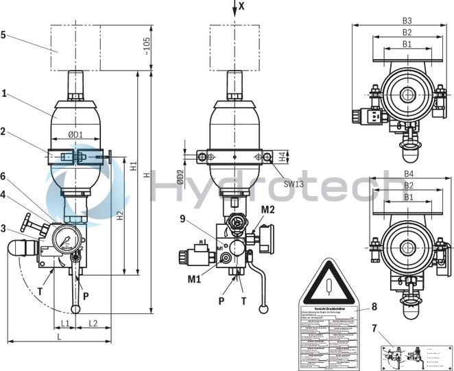
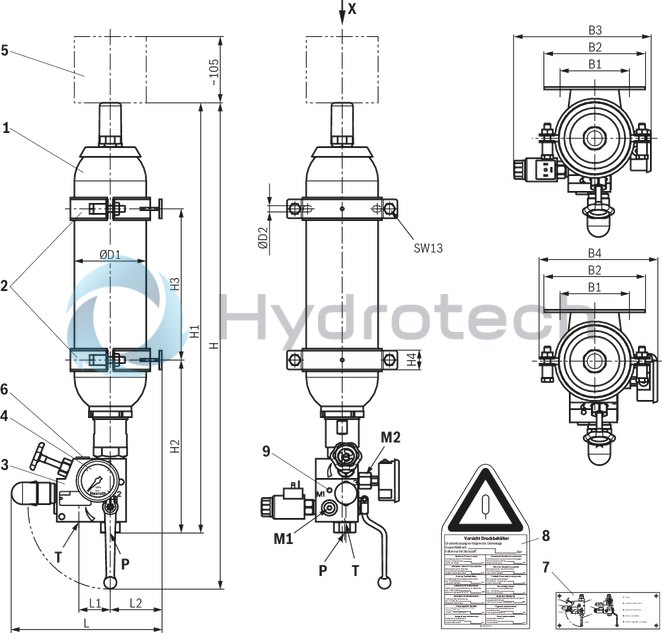
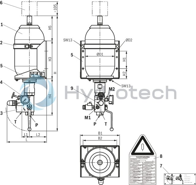
Dimensions: Mounting A in console
Accumulator station with 4 … 50 l bladder-type accumulator
Dimensions in mm
|
1 |
Hydraulic accumulator |
|
2 |
Clamp |
|
3 |
Shut-off block |
|
4 |
Pressure gauge with red indication of the maximum admissible operating pressure |
|
5 |
Console |
|
6 |
Space required for filling device |
|
7 |
Functional sign (loose) |
|
8 |
Warning sign (loose) |
|
9 |
Threaded connection M8 for equipotential bonding |
|
|
|
|
Connection designation |
|
|
M1 |
Measuring port G1/4 |
|
M2 |
Pressure gauge connection G1/4 |
|
P |
Pump connection see table |
|
T |
Tank port see table |
|
Gas filling pressure of the accumulators upon delivery: BA 0 barCE 0 barRussia 2 … 5 barChina 2 … 5 bar |
|
|
ABSBG-... assembly kit |
ØD1 |
ØD2 |
B1 |
B2 |
H1 |
H2 |
H3 |
H4 |
H5 |
H |
L1 |
L2 |
L |
P |
T |
|
|
max. |
|
|
|
|
|
|
|
|
|
max. |
|
|
|
|
|
|
|
mm |
mm |
mm |
mm |
mm |
mm |
mm |
mm |
mm |
mm |
mm |
mm |
mm |
mm |
|||
| B 4,0.../10... | 170 | 10 | 210 | 170 | 120 | 50 | 250 | 193 | ± 10 | 136 | 646 | 50 | 112 | 269 | G1/2 | G3/8 |
| B 4,0.../20... | 170 | 10 | 210 | 170 | 120 | 50 | 250 | 219 | ± 10 | 136 | 720 | 56 | 112 | 283 | G1 | G1/2 |
| B 10,0.../20... | 221 | 10 | 288 | 250 | 130 | 75 | 280 | 269 | ± 10 | 208 | 872 | 56 | 128 | 299 | G1 | G1/2 |
| B 10,0.../30... | 221 | 10 | 288 | 250 | 130 | 75 | 280 | 314 | ± 10 | 208 | 972 | 80 | 128 | 361 | G1 1/2 | G1/2 |
| B 10,0.../31... | 221 | 10 | 288 | 250 | 130 | 75 | 280 | 336 | ± 10 | 208 | 994 | 111 | 128 | 361 | G1 1/2 | G1 1/2 |
| B 20,0.../30... | 221 | 10 | 288 | 250 | 360 | 100 | 560 | 314 | ± 10 | 238 | 1282 | 80 | 126 | 359 | G1 1/2 | G1/2 |
| B 20,0.../31... | 221 | 10 | 288 | 250 | 360 | 100 | 560 | 336 | ± 10 | 238 | 1304 | 111 | 126 | 359 | G1 1/2 | G1 1/2 |
| B 24,0.../20... | 221 | 10 | 288 | 250 | 360 | 100 | 560 | 269 | ± 10 | 373 | 1317 | 56 | 126 | 297 | G1 | G1/2 |
| B 32,0.../30... | 221 | 12 | 288 | 250 | 820 | 150 | 1120 | 314 | ± 10 | 198 | 1802 | 80 | 127 | 360 | G1 1/2 | G1/2 |
| B 32,0.../31... | 221 | 12 | 288 | 250 | 820 | 150 | 1120 | 336 | ± 10 | 198 | 1824 | 111 | 127 | 360 | G1 1/2 | G1 1/2 |
| B 50,0.../30... | 221 | 12 | 288 | 250 | 820 | 150 | 1120 | 314 | ± 10 | 713 | 2317 | 80 | 127 | 360 | G1 1/2 | G1/2 |
| B 50,0.../31... | 221 | 12 | 288 | 250 | 820 | 150 | 1120 | 336 | ± 10 | 713 | 2339 | 111 | 127 | 360 | G1 1/2 | G1 1/2 |
| approx. dimensions - for precise dimensions, please refer to the dimensional drawings |
Commissioning, maintenance and operating instructions
General Information
Observe the documentation for the machinery. Also observe the documentation pertaining to the other components, assemblies and partly completed machinery, which form part of the complete machinery. Observe the generally applicable, legal or otherwise binding European and national regulations as well as the relevant legislation for your country pertaining to the prevention of accidents and protection of the environment. Operating instructions according to data sheet of the accumulator Depending on the country of installation, national pressure vessel regulations need to be complied with. In the standard, the country acceptance is effected according to BA, CE as well as for China and Russia Other acceptances on request. Please indicate the country of installation in the order. Keep all documents included in the delivery in a safe place; they will be required by the expert in recurring tests. The machine end-user will have sole responsibility for complying with existing provisions. The accumulator stations in this edition are assemblies in the sense of directive 2014/68/EU, article 2, section 6 (Pressure Equipment Directive).However, they are not intended for exclusive commissioning. They are installed as a component of a larger assembly or system. The accumulator stations described here contain the entire equipment which is required for safety reasons according to DIN EN ISO 4413. The accumulator stations must not be modified; otherwise, the operating license according to directive 2014/68/EU will be lost and the dealer and/or manufacturer warranty will be forfeited. The accumulator stations may only be operated within the admissible limit values. Repairs may only be carried out by the manufacturer or their authorized dealers and agencies. Repairs performed by third parties invalidate the approval and release the manufacturer from all claims resulting from an unauthorized intervention. Assembly and maintenance must be implemented by authorized, instructed persons only.The accumulator stations are provided with signs:1. Name plate specifying the pressure rating, identifies the device2. Functional sign, identifies the components and elementary lever positions3. Warning sign, has to be clearly visible and attached at the device or next to it.Usually, the warning sign is in the languages according to the country acceptance. Other languages on request.
For hydraulic systems with one or several hydraulic accumulators whose warning signs are not visible after installation into the machine, an additional warning sign has to be attached visibly to the system, stating:
"CAUTION - system contains hydraulic accumulators."The circuit diagram has to contain the same notice. With mounting "B" and "K", the warning signs and functional signs are supplied loosely and must be attached to or close to the accumulator station in a clearly visible position. The attachment of the signs must already be considered in the design.
1: Name plate
|
3: Warning sign
|
2: Functional sign
|
Commissioning - Operating instructions according to data sheet of the accumulator!
DANGER
Do not charge hydraulic accumulators with oxygen or air. Explosion hazard!
Prior to the initial commissioning, the hydraulic accumulator must be filled with nitrogen of class 4.0, pure (N2 content 99.99 vol. %).The preset gas pressure necessary for the operation is indicated in the circuit diagrams and operating instructions. Only use suitable filling and testing devices for filling.We recommend using the charging and test devices by Bosch Rexroth according to data sheet 50150.
WARNING
Risk of injury caused by improper assembly. Hydraulic accumulators are energy stores. They may supply the energy for uncontrolled movements to actuators. Before beginning any repairs, the system must be depressurized on the oil and gas side and protected against unauthorized re-start. Do not carry out welding and soldering works or any mechanical processing at the accumulator tank!Any kind of work at the product invalidates the declaration of conformity and the operating license!– Explosion hazard due to welding and soldering works!– Danger of bursting during and after mechanical processing. A warning sign is enclosed to the accumulator station. It is to be attached to or close to the accumulator station in a clearly visible position.
Maintenance
ATTENTION
In case of damage at the accumulator bladder or diaphragm, the accumulator will lose its function immediately. Loss of the initial gas tension will lead to damage at the accumulator bladder or the accumulator diaphragm if operation of the system is continued nevertheless. Check the initial gas tension in regular intervals.
Legal provisions
Hydraulic accumulators are pressure vessels and subject to the application national provisions and/or regulations valid at the place of installation. In Germany, the Ordinance on Industrial Safety and Health (BetrSichV) applies. As a standard, country acceptances are effected according to BA, CE as well as for China and Russia. Other acceptances on request. Special regulations are to be observed in shipbuilding, aircraft construction, mining, etc. Design, production and testing are effected according to the data sheets according to AD 2000. Installation, equipment and operation are controlled by the "Technical rules Pressure vessels" (TRB).
Note pursuant to the EC Machinery Directive 2006/42/EC, according to annex II part 1, section A, manufacturer's declaration:
The assemblies were manufactured in accordance with the harmonized standards DIN EN ISO 4413, DIN EN ISO 12100, EN 983 and EN 60204-1. Commissioning is prohibited until it was confirmed that the machine into which the assemblies are to be integrated complies with the regulations laid down in the EC Directives.Spare parts and accessories
Bladder-type accumulator according to data sheet 50171 Shut-off block manual/electrical according to data sheet 50131 Pressure gauge according to data sheet 50205 Warning sign according to RNI 17506-001Consoles contained in the assembly kit are intended for mounting by means of screws and nuts or for welding to suitable frames or design components.