
BOSCH REXROTH
R901282333
BOSCH REXROTH
MATERIAL: R901282333
SUMMARY:
Quantity in stock: 0
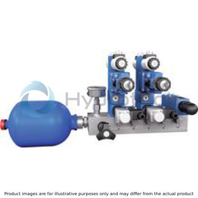
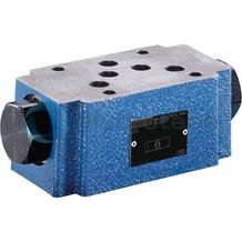
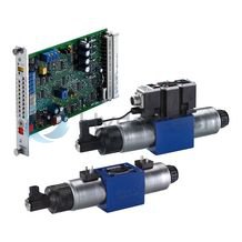
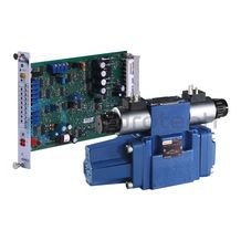
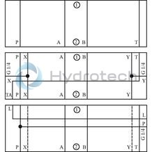
Manifolds are the base element for ready-for-connection controls in vertical stacking design. On each station, highly compact hydraulic controls can be build using vertically stackable sandwich plate valves in connection with on/off and proportional servo valves. All stations have a common pump and tank port (P2 and T2). The pump line is lead out at both front sides of the manifold. Every station is equipped with separate actuator ports "A" and "B” and measuring ports “MA” and “MB”. The actuator ports are located at the bottom side of the plate. The manifolds are prepared for the installation of a pressure relief valve type DBD 10 and a pressure gauge type ABZMM in channel P.
|
01 |
02 |
03 |
04 |
05 |
06 |
07 |
08 |
|||
|
Manifold |
HSR |
10 |
M |
‒ |
40 |
/ |
01 |
D |
|
Number of ready-for-connection controls in vertical stacking design |
||
|
01 |
1 Control |
1 |
|
2 controls |
2 |
|
|
3 Controls |
3 |
|
|
4 controls |
4 |
|
|
5 controls |
5 |
|
|
6 controls |
6 |
|
|
7 controls |
7 |
|
|
8 controls |
8 |
|
|
02 |
Manifold |
HSR |
|
Size |
||
|
03 |
Size 10 |
10 |
|
Measuring ports |
||
|
04 |
With measuring ports in the actuator ports A and B |
M |
|
Component series |
||
|
05 |
Manifold with installation possibility for a pressure relief valve type DBD 10 (with NG10) and attachment possibility for a pressure gauge type ABZMM in pressure channel P |
40 |
|
Connection thread |
||
|
06 |
Pipe thread according to ISO 228 Part 1 |
01 |
|
Position of actuator ports |
||
|
07 |
At the bottom |
D |
|
Coating |
||
|
08 |
Galvanic coating DIN 50979 |
FE//ZN8//CN/T0 |
|
Phosphate coating according to DIN EN 12476 |
PHOSPHATED 1) |
|
| 1) | Manganese or zinc phosphate coating |
Required ordering code of a completely mounted manifold
Example:
2-fold manifold
|
Position |
Quantity |
Device designation |
Type designation |
Material number |
|
.0 |
1 |
2HSR06MD4X...C736A/G24N9K4M011) |
1) |
|
|
.01 |
1 |
Manifold |
2HSR06M-40/01D PHOSPHATED |
R900731949 |
|
.11 |
1 |
Check valve |
Z1S 6 P15-4X/N |
R901219725 |
|
.12 |
1 |
Sandwich plate |
HSZ 06 A431-1X/LJ4M00 |
R900971827 |
|
.13 |
1 |
Check valve |
Z2S 6B1-6X/ |
R900347501 |
|
.14 |
1 |
Directional spool valve |
4WE 6 H73-6X/EG24N9K4/A12 |
R900906660 |
|
4 |
Stud screw |
DIN939-M5X180-10.9 |
R900028125 |
|
|
4 |
Round nut |
ZN10035-M5-ST |
R913020308 |
|
|
.21 |
1 |
Flow control valve |
Z2FRM 6 TB2-2X/6QRV |
R900910912 |
|
.22 |
1 |
Cover plate |
HSA 06 A005-4X/M00 |
R901092289 |
|
4 |
Hexagon socket head cap screw |
ISO4762-M5X80-10.9-F& |
R913000070 |
|
|
.31 |
1 |
Pressure relief valve |
DBDS 6 K1X/315P220 |
R900773948 |
|
.32 |
1 |
Measuring coupling |
MCS20-SDS-E-G1/4-ST3N00Z-M |
R900009090 |
|
.33 |
1 |
Measuring coupling |
MCS20-SDS-E-G1/4-ST3N00Z-M |
R900009090 |
|
.34 |
1 |
Measuring coupling |
MCS20-SDS-E-G1/4-ST3N00Z-M |
R900009090 |
|
.35 |
1 |
Measuring coupling |
MCS20-SDS-E-G1/4-ST3N00Z-M |
R900009090 |
|
.36 |
1 |
Pressure gauge |
ABZMM 63- 400BAR/MPA-R/B-G |
R900022459 |
|
1 |
Assembly kit |
AB-G1/4-G-G1/4-NBR |
R901126946 |
|
|
2 |
Plug screw |
ZN10001-G3/8A-N-ST |
R913011602 |
|
|
For port A2, B2: |
||||
|
1 |
Plug screw |
ZN1001-G1/2A-N-ST |
R913011603 |
|
|
For port P1: |
||||
|
1 |
Name plate |
RNI-17620-001-REXROTH |
R900002783 |
| 1) | Material number and short designation of the type are defined by Rexroth. |
|
Size |
10 | |
|
Stations |
from 1 ... 8 | |
|
Material |
GGG40 | |
|
Surface coating |
Galvanic coating according to DIN 50979 (FE//ZN8//CN//T0) Phosphate coating according to DIN EN 12476 with after-treatment (greases, oils, lubricants) (FE//ZNPH/R/5/T4 or FE//MNPH/R/5/T4) |
|
|
Operating pressure max. 1) |
bar |
315 |
|
Hydraulic fluid |
see table below | |
|
Fixing holes |
4 x M8 front threads for vertical attachment, 2 through holes ø9 for front attachment | |
| 1) | Manifold without valve fitting |
|
Hydraulic fluid |
Classification |
Standards |
Data sheet |
|
|
Mineral oil |
Mineral oil HLP |
DIN 51524 |
90220 |
|
|
Bio-degradable |
Insoluble in water |
Triglycerides (rape seed oil) HETG |
ISO 15380 |
90221 |
|
Synthetic esters HEES |
||||
|
Soluble in water |
Polyglycols HEPG |
ISO 15380 |
||
|
Flame-resistant |
Water-free |
Organic esters HFDU, phosphoric acid esters HFDR |
ISO 12922 |
90222 |
|
Containing water |
Emulsions HFA-E, aqueous solution HFC |
ISO 12922 |
90223 |
|
Important information on hydraulic fluids:
For further information and data on the use of other hydraulic fluids, please refer to the data sheets above or contact us. Some hydraulic fluids (HFC, HFD ...) may attack and destroy galvanized surfaces. Phosphatized plates (zinc phosphate coating, if applicable) are therefore not suitable. The zinc content of plates with galvanized insides, however, is very low. After a flushing procedure with subsequent filter exchange, the zinc is washed out. Special caution is required regarding leaking hydraulic fluid, especially during maintenance and disassembly of the manifold.Notice:
For the installation, commissioning and maintenance of oil hydraulic systems, please observe data sheet 07900.
For applications outside these parameters, please consult us!
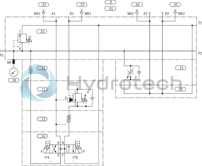
Manifolds with 4 stations
Manifold 4HSR10M-40/01D
Notice:
The pressure relief valves are not included in the scope of delivery.
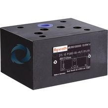
Check valve
Z1S 10
Check valve
Z1S 10
Size 10 Component series 4X Maximum operating pressure 350 bar Maximum flow 100 l/minData sheet
Operating Instructions
Configurator / CAD
Spare parts & repair
Check valves, pilot operated
Z2S 10
Check valves, pilot operated
Z2S 10
Size 10 Component series 3X Maximum operating pressure 315 bar Maximum flow 120 l/minData sheet
Operating Instructions
Configurator / CAD
Spare parts & repair
3/2 and 4/2 directional seat valve with solenoid actuation
M-.SED 10
3/2 and 4/2 directional seat valve with solenoid actuation
M-.SED 10
Size 10 Component series 1X Maximum operating pressure 350 bar Maximum flow 40 l/minData sheet
Operating Instructions
Configurator / CAD
Spare parts & repair
3/2 and 4/2 directional seat valve with solenoid actuation
M-.SEW 10
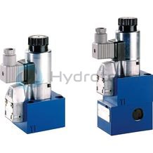
3/2 and 4/2 directional seat valve with solenoid actuation
M-.SEW 10
Size 10 Component series 1X Maximum operating pressure 420 / 630 bar Maximum flow 40 l/minData sheet
Operating Instructions
Configurator / CAD
Spare parts & repair
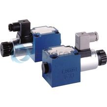
Directional spool valves, direct operated, with manual actuation
WMM 10
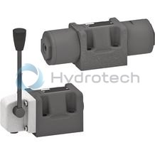
Directional spool valves, direct operated, with manual actuation
WMM 10
Size 10 Component series 5X Maximum operating pressure 350 bar Maximum flow 160 l/minData sheet
Spare parts & repair
Directional spool valves, direct operated, with fluidic actuation
WN 10
Directional spool valves, direct operated, with fluidic actuation
WN 10
Size 10 Component series 5X Maximum operating pressure 350 bar Maximum flow 160 l/minData sheet
Spare parts & repair
Directional spool valves, direct operated, with fluidic actuation
WP 10
Directional spool valves, direct operated, with fluidic actuation
WP 10
Size 10 Component series 5X Maximum operating pressure 350 bar Maximum flow 160 l/minData sheet
Spare parts & repair
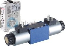
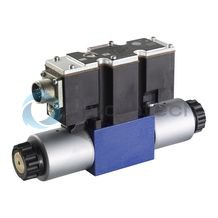
Directional spool valves, direct operated, with solenoid actuation
WE 10...E
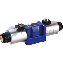
Directional spool valves, direct operated, with solenoid actuation
WE 10...E
Size 10 Component series 5X Maximum operating pressure 350 bar Maximum flow 160 l/minData sheet
Configurator / CAD
Spare parts & repair
Directional spool valves, pilot operated, with electro-hydraulic actuation
WEH
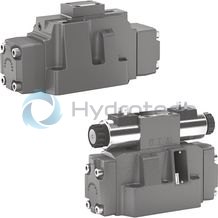
Directional spool valves, pilot operated, with electro-hydraulic actuation
WEH
Size 10, 16, 25 (WEH22), 25 (WEH25), 32 Component series 4X, 7X, 6X Maximum operating pressure 280 bar Maximum flow 1100 l/minData sheet
Operating Instructions
Configurator / CAD
Spare parts & repair
Pressure relief valve, direct controlled
DBD
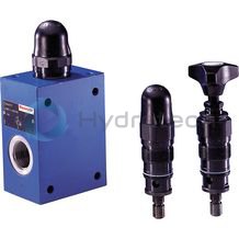
Pressure relief valve, direct controlled
DBD
Size 6 … 30 Component series 1X Maximum operating pressure 630 barData sheet
Operating instructions
Configurator / CAD
Spare parts & repair
Pressure relief valve, pilot controlled
ZDB 10, Z2DB 10
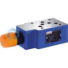
Pressure relief valve, pilot controlled
ZDB 10, Z2DB 10
Size 10 Component series 4X Maximum operating pressure 315 bar Maximum flow 100 l/minData sheet
Configurator / CAD
Spare parts & repair
Pressure reducing valve, direct operated
ZDR 10 D
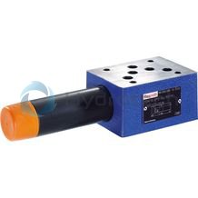
Pressure reducing valve, direct operated
ZDR 10 D
Size 10 Component series 5X Maximum operating pressure 210 bar Maximum flow 80 l/minData sheet
Configurator / CAD
Spare parts & repair
Throttle check valve
Z2FS 10
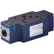
Throttle check valve
Z2FS 10
Size 10 Component series 3X Maximum operating pressure 315 bar Maximum flow 160 l/minData sheet
Configurator / CAD
Spare parts & repair
4/2 and 4/3 proportional directional valves, direct operated, without electrical position feedback, without integrated electronics (OBE)
4WRA
4/2 and 4/3 proportional directional valves, direct operated, without electrical position feedback, without integrated electronics (OBE)
4WRA
Size 6, 10 Component series 2X Maximum operating pressure 315 bar Maximum flow 75 l/minData sheet
Environmental compatibility statement
Configurator / CAD
Spare parts & repair
4/2 and 4/3 proportional directional valves, direct operated, without electrical position feedback, with integrated electronics (OBE)
4WRAE
4/2 and 4/3 proportional directional valves, direct operated, without electrical position feedback, with integrated electronics (OBE)
4WRAE
Size 6, 10 Component series 2X Maximum operating pressure 315 bar Maximum flow 75 l/minData sheet
Environmental compatibility statement
Configurator / CAD
Spare parts & repair
4/2 and 4/3 proportional directional valves, direct operated, wit electrical position feedback, without integrated electronics (OBE)
4WRE
4/2 and 4/3 proportional directional valves, direct operated, wit electrical position feedback, without integrated electronics (OBE)
4WRE
Size 6 Component series 2X Maximum operating pressure 315 bar Maximum flow 80 l/minData sheet
Environmental compatibility statement
Configurator / CAD
Spare parts & repair
4/2 and 4/3 proportional directional valves, direct operated, wit electrical position feedback, with integrated electronics (OBE)
4WREE
4/2 and 4/3 proportional directional valves, direct operated, wit electrical position feedback, with integrated electronics (OBE)
4WREE
Size 6, 10 Component series 2X Maximum operating pressure 315 bar Maximum flow 180 l/minData sheet
Environmental compatibility statement
Configurator / CAD
Spare parts & repair
Proportional directional valves, pilot operated, without electrical position feedback, without integrated electronics (OBE)
4WRZ
Proportional directional valves, pilot operated, without electrical position feedback, without integrated electronics (OBE)
4WRZ
Size 10, 16, 25, 32, 52 Component series 7X Maximum operating pressure 350 bar Maximum flow 2800 l/minData sheet
Environmental compatibility statement
Configurator / CAD
Spare parts & repair
Proportional directional valves, pilot operated, without electrical position feedback, with integrated electronics (OBE)
4WRZE
Proportional directional valves, pilot operated, without electrical position feedback, with integrated electronics (OBE)
4WRZE
Size 10, 16, 25, 32, 52 Component series 7X Maximum operating pressure 350 bar Maximum flow 2800 l/minData sheet
Environmental compatibility statement
Configurator / CAD
Spare parts & repair
4/3 proportional directional valve, pilot-operated, without electrical position feedback, without integrated electronics (OBE)
4WRH
4/3 proportional directional valve, pilot-operated, without electrical position feedback, without integrated electronics (OBE)
4WRH
Size 10, 16, 25, 32, 52 Component series 7X Maximum operating pressure 350 bar Maximum flow 2800 l/minData sheet
Environmental compatibility statement
Configurator / CAD
Spare parts & repair
Cover plates
HSA
Cover plates
HSA
Size 6, 4, 5, 10, 16, 20, 22, 30, 32, 35 Maximum operating pressure 315 barData sheet
Spare parts & repair
Adapter plates
HSE
Adapter plates
HSE
Size 4 … 32 Maximum operating pressure 630 bar, 315 barData sheet
Spare parts & repair
Sandwich plates
HSZ 10
Sandwich plates
HSZ 10
Size 10 Maximum operating pressure 315 barData sheet
Spare parts & repair
Hydro-electric piston type pressure switches
HED 8 -2X
Hydro-electric piston type pressure switches
HED 8 -2X
Component series 2X Maximum operating pressure 630bar Pressure ratings 50, 100, 200, 350 and 630 bar UL recognized component, CCC-certifiedData sheet
Configurator / CAD
Spare parts & repair
Pressure gauge with fluid filling
ABZMM
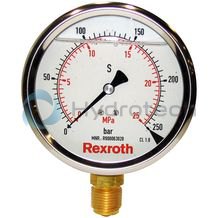
Pressure gauge with fluid filling
ABZMM
Data sheet
Spare parts & repair
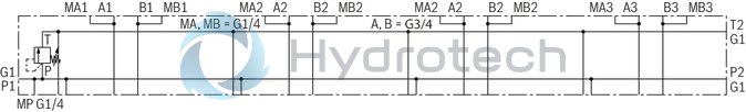
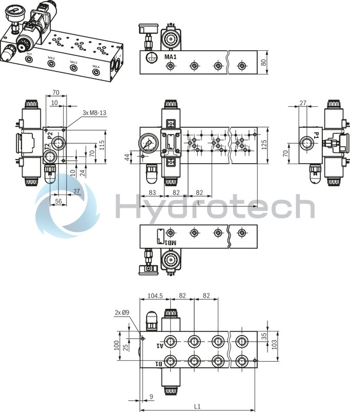
Manifold 1-8HSR10M-40/01C S08
Dimensions in mm
|
Number of stations |
L |
L1 |
|
mm |
mm |
|
| 1 | 157 | 149 |
| 2 | 239 | 231 |
| 3 | 321 | 313 |
| 4 | 403 | 395 |
| 5 | 485 | 477 |
| 6 | 567 | 559 |
| 7 | 649 | 641 |
| 8 | 731 | 723 |
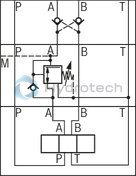
Pressure reducing valve in connection with check valve
The pressure reducing valve type ZDR .. DA (pressure reduction in channel A) must always be installed between the directional valve and the check valve type Z2S... This ensures that the check valve can block in a leak-free manner.
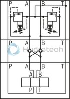
Pressure relief valve in connection with check valve
Leak-free blocking of the actuator is not possible if a pressure relief valve type ZDB../Z2DB.. is effective in channel A and/or B and a check valve is installed.
Pressure switch in connection with throttle check valve
Supply control
The pressure switch type HED 8 OH, effective in channel A and/or B, is installed between the subplate and the throttle check valve type Z2FS.
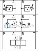
Discharge control
The pressure switch type HED 8 OH, effective in channel A and/or B, is installed between the directional valve and the throttle check valve type Z2FS.
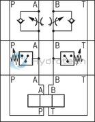
Notice:
The illustrated sections of circuit diagrams are examples. The project planning information must also be observed for valves with a similar function.
Mounting screws dependent on the valve fitting
Stud screw M5 DIN 939, property class 10.9
Dimensions in mm
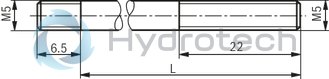
| 1) | L = length of the stud screws according to DIN 939 |
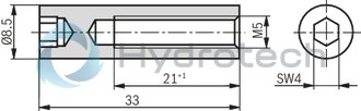
Round nut ZN10035-M5-ST, material no.: R913020308
Dimensions in mm
Stud screw M6 DIN 939, property class 10.9
Dimensions in mm
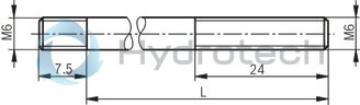
| 1) | L = length of the stud screws according to DIN 939 |
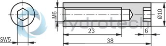
Round nut ZN10035-M6-ST, material no.: R913020310
Dimensions in mm
Notice:
The length of the mounting screws of the attached vertical stackings have to be calculated individually. Up to 115 mm, hexagon socket head cap screw according to ISO 4762 with stability 10.9 may be used. From 120 mm, stud screws according to DIN 939 or threaded bolts with stability 10.9 and corresponding round nuts are to be used. For the tightening torques, please refer to the data sheets of the valves used.