
HENGST FILTERS
1012843B
R928048007
HENGST FILTERS
MATERIAL: R928048007
SUMMARY:
Quantity in stock: 0
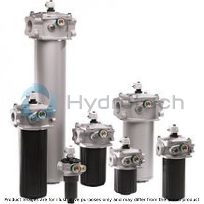
The tank mounted return line filter is provided in the return line for direct attachment onto the tank of a hydraulic or lubrication system. It can also be used as filling or bypass filter. It basically consists of filter head (1), filter bowl (2), cover (3), filter element (4) as well as a bypass valve (5), by default.
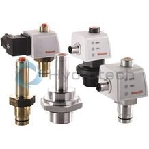
Optionally, the filter is equipped with mechanical/visual maintenance indicator (6). The electronic maintenance indicator is connected via the electronic switching element (7) with 1 or 2 switching points (see p. 7), which has to be ordered separately.
During operation, the hydraulic fluid reaches the filter housing via the inlet; here, it flows through the filter element (5) from the outside to the inside and is cleaned according to the filter rating. The dirt particles filtered out settle in the filter bowl (3) and in the filter element (5). Via the outlet, the filtered hydraulic fluid enters the tank. In case of contamination, the necessary filter element exchange is displayed by the maintenance indicator (7).
The electronic switching element (7) is attached to the mechanical/visual maintenance indicator (6) and held by means of a locking ring.
Depending on the filter size, more additional functions (only for NG0040 ... 0100) are available - e.g. a breathing filter (8), surge protection (9) or return pipes (10) in different lengths – in this connection, also refer to the chapter “Ordering code Accessories”.

|
01 |
02 |
03 |
04 |
05 |
06 |
07 |
08 |
09 |
|||||
|
10TE |
‒ |
A00 |
‒ |
‒ |
‒ |
‒ |
|
Series |
|||||||||||
|
01 |
Return flow filter, simple, 10 bar |
10TE |
|||||||||
|
Filter element |
|||||||||||
|
02 |
with filter element according to DIN 24550 |
N |
|||||||||
|
Size |
|||||||||||
|
03 |
TEN... |
0040 |
|||||||||
|
0063 |
|||||||||||
|
0100 |
|||||||||||
|
0160 |
|||||||||||
|
0250 |
|||||||||||
|
0400 |
|||||||||||
|
0630 |
|||||||||||
|
1000 |
|||||||||||
|
TE... |
2000 |
||||||||||
|
2500 |
|||||||||||
|
Filter rating in μm |
|||||||||||
|
04 |
Nominal |
Paper, not cleanable |
P10 |
||||||||
|
P25 |
|||||||||||
|
Nominal |
Stainless steel wire mesh, cleanable |
G10 |
|||||||||
|
G25 |
|||||||||||
|
G40 |
|||||||||||
|
G60 |
|||||||||||
|
G100 |
|||||||||||
|
Absolute |
Non-woven glass fiber media, not cleanable |
H3XL |
|||||||||
|
H6XL |
|||||||||||
|
H20XL |
|||||||||||
|
Glass fiber material generation 5, non-reusable, not cleanable |
PWR10 |
||||||||||
|
Absolute |
Water-absorbing, not cleanable |
AS3 |
|||||||||
|
AS6 |
|||||||||||
|
AS10 |
|||||||||||
|
AS20 |
|||||||||||
|
Pressure differential |
|||||||||||
|
05 |
max. admissible pressure differential of the filter element |
30 bar ‒ Filter with bypass valve |
A00 |
||||||||
|
Maintenance indicator |
|||||||||||
|
06 |
without maintenance indicator |
Bypass cracking pressure 3.5 bar |
0 |
||||||||
|
Pressure gauge 0...6 bar right 1) |
Bypass cracking pressure 3.5 bar |
MR |
|||||||||
|
Pressure gauge 0…6 bar left |
1) |
Bypass cracking pressure 3.5 bar |
ML |
||||||||
|
Maintenance indicator, mech./visual, switching pressure 2.2 bar |
Bypass cracking pressure 3.5 bar |
Aluminium |
MRV2,2 |
||||||||
|
Maintenance indicator, mech./visual, switching pressure 2.2 bar |
Aluminium |
with |
Pressure gauge 0...6 bar right 1) |
Bypass cracking pressure 3.5 bar |
MLV2,2 |
||||||
|
Maintenance indicator, mech./visual, switching pressure 2.2 bar |
Bypass cracking pressure 3.5 bar |
Polyamide |
P2,2 |
||||||||
|
Maintenance indicator, mech./visual, switching pressure 0.8 bar |
Bypass cracking pressure 3.5 bar |
Aluminium |
V0,8 |
||||||||
|
Maintenance indicator, mechanical/visual, switching pressure 1.5 bar |
Bypass cracking pressure 3.5 bar |
Aluminium |
V1,5 |
||||||||
|
Maintenance indicator, mech./visual, switching pressure 2.2 bar |
Bypass cracking pressure 3.5 bar |
Aluminium |
V2,2 |
||||||||
|
Seal |
|||||||||||
|
07 |
NBR |
M |
|||||||||
|
FKM |
V |
||||||||||
|
Connection |
|||||||||||
|
08 |
Frame size |
0040 |
0063…0100 |
0160 |
0250 |
0400 |
0630 |
1000 |
2000 |
2500 |
|
|
Connection |
|||||||||||
|
G 3/4 |
• |
x x |
‒ |
R3 |
|||||||
|
G 1 |
x |
• |
R4 |
||||||||
|
1 1/16-12 UN-2B |
x |
x |
U4 |
||||||||
|
1 5/16-12 UN-2B |
x |
x |
U9 |
||||||||
|
G1 1/4 |
‒ |
• |
x |
‒ |
R5 |
||||||
|
G1 1/2 |
x |
• |
R6 |
||||||||
|
SAE1 1/4 - 3000 psi |
x |
x |
S5 |
||||||||
|
SAE1 1/2 - 3000 psi |
x |
x |
S6 |
||||||||
|
1 7/8-12 UN-2B |
x |
x |
U6 |
||||||||
|
SAE2" 3000 psi |
‒ |
• |
x |
‒ |
S8 |
||||||
|
SAE2 1/2" 3000 psi |
x |
• |
S9 |
||||||||
|
SAE3" 3000 psi |
‒ |
• |
x |
x |
S10 |
||||||
|
SAE4" 3000 psi |
x |
• |
• |
S12 |
|||||||
|
● |
Standard port |
x |
Alternative connection possibility |
‒ |
not possible |
||||||
|
Supplementary information |
|||||||||||
|
09 |
Breathing filter |
F |
|||||||||
|
Breathing filter with surge protection |
FN |
||||||||||
|
Threaded coupling right (not possible with pressure gauge right) |
MR |
||||||||||
|
Threaded coupling left (not possible with pressure gauge left) |
ML |
||||||||||
|
Without bypass valve |
NB |
||||||||||
|
Outlet pipe L110 mm |
R110 |
||||||||||
|
Outlet pipe L150 mm |
R150 |
||||||||||
|
Outlet pipe L250 mm |
R250 |
||||||||||
|
Further versions are available upon request. |
|||||||||||
|
Hydraulic fluid |
Classification |
Suitable sealing materials |
Suitable adhesive |
Standards |
|
|
Mineral oil |
HLP |
NBR |
Standard |
DIN 51424 |
|
|
Bio-degradable |
Insoluble in water |
HETG |
NBR |
VDMA 24568 |
|
|
HEES |
FKM |
||||
|
Soluble in water |
HEPG |
FKM |
VDMA 24568 |
||
|
Flame-resistant |
Water-free |
HFDU, HFDR |
FKM |
VDMA 24317 |
|
|
Containing water |
HFAS |
NBR |
DIN 24320 |
||
|
HFAE |
NBR |
||||
|
HFC |
NBR |
VDMA 24317 |
|||
|
Skydrol |
‒ |
EPDM |
Special “H” |
‒ |
|
General
|
Type / version |
10 TEN | 10 TE | ||||||||||
|
Size |
0040 | 0063 | 0100 | 0160 | 0250 | 0400 | 0630 | 1000 | 2000 | 2500 | ||
|
Connection |
Standard |
G3/4 | G1 1/4 | G1 1/2 | SAE 2", 3000 psi | SAE 2 1/2", 3000 psi | SAE 3", 3000 psi | SAE 4", 3000 psi | ||||
|
optional |
G1 1 1/16-12 UN-2B 1 5/16-12 UN-2B |
G3/4 1 1/16-12 UN-2B 1 5/16-12 UN-2B |
G1 1/2 SAE 1 1/4“ 3000 psi SAE 1 1/2“ 3000 psi 1 7/8-12 UN-2B |
G1 1/4 SAE 1 1/4“ 3000 psi SAE 1 1/2“ 3000 psi 1 7/8-12 UN-2B |
SAE 2 1/2", 3000 psi | SAE 2", 3000 psi | SAE 4", 3000 psi | SAE 3", 3000 psi | ||||
|
Ambient temperature range |
°C |
-10 … +65 | ||||||||||
|
Installation position |
Vertical | |||||||||||
|
Filtration direction |
From the outside to the inside | |||||||||||
|
Fatigue strength according to ISO 10771 |
> 10⁵ with max. operating pressure | |||||||||||
|
Material |
Filter cover |
carbon fiber reinforced plastic | ||||||||||
|
Filter head |
Aluminium | |||||||||||
|
Filter bowl |
carbon fiber reinforced plastic | |||||||||||
|
Seals |
NBR / FKM | |||||||||||
|
Weight |
kg |
1.4 | 1.6 | 1.8 | 4.5 | 5 | 8 | 10 | 18 | 21.5 | 27 | |
hydraulic
|
Type / version |
10 TEN | 10 TE | ||||||||||
|
Size |
0040 | 0063 | 0100 | 0160 | 0250 | 0400 | 0630 | 1000 | 2000 | 2500 | ||
|
Flow, max. |
l/min |
62 | 80 | 95 | 260 | 320 | 560 | 630 | 1270 | 1600 | 1680 | |
|
Max. operating pressure |
bar |
10 | ||||||||||
|
Operating temperature range |
°C |
-10 … +100 | ||||||||||
|
Cracking pressure |
Bypass valve |
bar |
3 ±0.3 | |||||||||
|
Hydraulic fluid temperature range |
°C |
-10 … +100 | ||||||||||
|
Minimum conductivity of the medium |
pS/m |
300 | ||||||||||
Important information on hydraulic fluids!
For more information and data on the use of other hydraulic fluids, please refer to data sheet 90220 or contact us! Flame-resistant – containing water: Due to possible chemical reactions with materials or surface coatings of machine and system components, the service life with these hydraulic fluids may be less than expected. Filter materials made of filter paper P must not be used, filter elements with glass fiber material have to be used instead. Bio-degradable: If filter materials made of filter paper are used, the filter life may be shorter than expected due to material incompatibility and swelling.|
Hydraulic fluid |
Classification |
Suitable sealing materials |
Suitable adhesive |
Standards |
|
|
Mineral oil |
HLP |
NBR |
Standard |
DIN 51424 |
|
|
Bio-degradable |
Insoluble in water |
HETG |
NBR |
VDMA 24568 |
|
|
HEES |
FKM |
||||
|
Soluble in water |
HEPG |
FKM |
VDMA 24568 |
||
|
Flame-resistant |
Water-free |
HFDU, HFDR |
FKM |
VDMA 24317 |
|
|
Containing water |
HFAS |
NBR |
DIN 24320 |
||
|
HFAE |
NBR |
||||
|
HFC |
NBR |
VDMA 24317 |
|||
|
Skydrol |
‒ |
EPDM |
Special “H” |
‒ |
|
For applications outside these parameters, please consult us!
Filter element (measured with mineral oil HLP46 according to DIN 51524)
Spec. weight: < 0.9 kg/dm3
Δp-Q characteristic curves for complete filter, recommended initial Δp for design = 0.5 bar
Selection of the perfect filter is made possible by our online “Bosch Rexroth FilterSelect“ design software.
10TEN0040-H3XL

10TEN0063-H3XL

10TEN0100-H3XL

10TEN0160-H3XL

10TEN0250-H3XL

10TEN0400-H3XL

10TEN0630-H3XL

10TEN1000-H3XL

10TE2000-H3XL

10TE2500-H3XL

10TEN0040-H10XL

10TEN0063-H10XL

10TEN0100-H10XL

10TEN0160-H10XL

10TEN0250-H10XL

10TEN0400-H10XL

10TEN0630-H10XL

10TEN1000-H10XL

10TE2000-H10XL

10TE2500-H10XL


Maintenance
If at operating temperature, the red indicator pin reaches out of the mechanical/visual maintenance indicator and/or if the switching process in the electronic switching element is triggered, the filter element is contaminated and needs to be replaced and cleaned respectively. More details see data sheet for filter elements.
The material number of the corresponding replacement filter element is indicated on the name plate of the complete filter. It must comply with the material number on the filter element.
Switch off the system, discharge the filter on the pressure side.
Screw off the filter cover (NG0040-0100) and/or loosen the screws (from NG0160) and remove the filter cover upwards.
Notice:
Note that with lower ratings, it may take slightly longer to discharge the residual oil. If the filter element is removed before the residual oil has been discharged, contaminated oil may reach the clean side.
Remove the filter element including filter bowl. From frame size 0160, the filter bowls are equipped with removal brackets.
Remove the filter element from the spigot in the filter bowl by rotating it slightly; clean the filter components if necessary.
Check the seals at filter cover and filter bowl for damage and renew them, if necessary. For suitable seal kits refer to chapter “Ordering code Spare parts”.
Filter elements made of wire mesh can be cleaned. For detailed cleaning instructions refer to the data sheet for filter elements.
Install the new or cleaned filter element on the spigot again by slightly rotating it.
The filter is to be assembled in reverse order. The torque specifications (“Tightening torques” chapter) are to be observed.
Commissioning
Commission the system.
Notice:
There is no bleeding provided at the filter.
Assembly:
The max. operating pressure of the system must not exceed the max. adm. operating pressure of the filter (see name plate).
Before the assembly, the hole pattern of the tank must be compared to the dimensions from the "Dimensions" chapter.
As of a length of approx. 500 mm, drain pipes must be led in a bracket in order to avoid oscillations caused by the fluid flow in the tank. It is moreover to be ensured that in case of maintenance works, the filter bowl and the outlet pipe are pulled out of the filter head together.
During assembly of the filter (see also chapter “Tightening torques”), the flow direction (direction arrows) and the required servicing height of the filter element (see chapter “Dimensions”) are to be considered.
Perfect functioning is only guaranteed in the installation position filter bowl vertically downwards and ON the tank.
The maintenance indicator must be arranged in a well visible way.
Remove the plastic plugs in the filter inlet and outlet.
Ensure that the system is assembled without tension stress.
The optional electric maintenance indicator is connected via the electric switching element with 1 or 2 switching points, which is attached to the mechanical/visual maintenance indicator and held by means of the locking ring. More details see data sheet “Maintenance indicator”.
Notices:
Assemble and disassemble only with depressurized system! For the filter element exchange refer to “Maintenance”. Tank is pressurized! Do not operate the switching lever during the filter element exchange. Do not exchange the optical/mechanical maintenance indicator while the filter is under pressure! If the flow direction is not considered during assembly, the filter element will be destroyed. Particle contaminates could enter the system and damage the downstream components.
|
Ordering code |
Option maintenance indicator |
Position |
Frame size |
|
|
0040…0100 |
0160…2500 |
|||
|
P2,2; V0,8; V1,5; V2,2 |
Mechanical/visual maintenance indicator |
1 |
• |
• |
|
MR |
Pressure gauge right |
3a |
• |
‒ |
|
ML |
Pressure gauge left |
3b |
‒ |
• |
|
V2,2MR |
Mechanical/visual maintenance indicator and pressure gauge right |
1 + 3a |
• |
‒ |
|
V2,2ML |
Mechanical/visual maintenance indicator and pressure gauge left |
1 + 3b |
‒ |
• |
|
+ R928… |
Electronic switching element |
See Accessories |
||
|
Ordering code |
Option Supplementary information |
Position |
Frame size |
|
|
F |
Breathing filter |
4 |
• |
‒ |
|
FN |
Breathing filter with surge protection |
4 + 5 |
• |
‒ |
|
MR |
Threaded coupling right (not possible with pressure gauge right) |
3a |
• |
‒ |
|
ML |
Threaded coupling left (not possible with pressure gauge left) |
3b |
‒ |
• |
|
NB |
Without bypass valve |
• |
• |
|
|
R110 |
Outlet pipe L110 mm |
6 |
• 1) |
‒ |
|
R150 |
Outlet pipe L150 mm |
6 |
• 1) |
‒ |
|
R250 |
Outlet pipe L250 mm |
6 |
• 1) |
‒ |
|
1) |
Outlet pipes for sizes 0040…0100 are preferably to be ordered pre-assembled via the complete filter. Outlet pipes for others sizes must be ordered separately and are not pre-assembled. |
|||
|
• |
optional |
‒ |
not possible |
|
Electronic switching elements
WE-.SP
Electronic switching elements
WE-.SP
Operating temperature -30 … +85 °CData sheet
Spare parts & repair
Electronic switching elements
WE-S02
Electronic switching elements
WE-S02
Max. operating pressure 40 bar Operating temperature -10 … +100 °CData sheet
Spare parts & repair
Backpressure indicators for return line filters
WO-S01
Backpressure indicators for return line filters
WO-S01
Max. operating pressure 10 bar Operating temperature -30 … +100 °CData sheet
Spare parts & repair
Backpressure indicators for return line filters
WO-S02
Backpressure indicators for return line filters
WO-S02
Max. operating pressure 10 bar Operating temperature -10 … +100 °CData sheet
Spare parts & repair