
HENGST OF NORTH AMERICA
1007002B
R928030772
HENGST OF NORTH AMERICA
MATERIAL: R928030772
SUMMARY:
Quantity in stock: 0
Inline filters are used in hydraulic systems for separating solid materials from fluids and lubricating oils.
They are intended for attachment in pipelines.
The 245LE(N) inline filter is suitable for inline installation.
It basically consists of filter head (1), a screwable filter bowl (2), filter element (3) as well as mechanical/visual maintenance indicator (4). In case of filters with low-pressure-differential-stable filter elements (= code letter pressure differential A), there is an assembled bypass valve (5) by default.
Via the inlet, the fluid reaches the filter element (3) where it is cleaned. The dirt particles filtered out settle in the filter element (3). Via the outlet, the filtered fluid enters the hydraulic circuit.
The filter housing and all connection elements are designed so that pressure peaks - as they may e.g. occur in case of abrupt opening of large control valves due to the accelerated fluid quantity - can be securely absorbed. As of size 0160, the standard equipment comprises a drain screw (7).
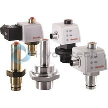
By default, the filter is equipped with mechanical/visual maintenance indicator (4). The electronic switching element (8) which has to be ordered separately is attached to the mechanical/visual maintenance indicator (4) and held by means of a locking ring.
The electronic switching elements with 1 or 2 switching points are connected via a mating connector according to IEC-60947-5-2 or via a cable connection according to EN17301-803.
WARNING!
If the maintenance indicator for the element exchange is not observed, the bypass valve will open if the pressure differential increases. In this way, one part of the flow reaches the clean side of the filter without being filtered. Thus, effective filtration is no longer guaranteed.
245LE(N) NG0040 … NG0400

|
01 |
02 |
03 |
04 |
05 |
06 |
07 |
08 |
09 |
|||||
|
245LE |
N |
– |
– |
– |
– |
– |
|
Frame size |
|||||||
|
01 |
Inline filter 250 bar |
245LE |
|||||
|
Filter element |
|||||||
|
02 |
with filter element according to DIN 24550 |
N |
|||||
|
Size |
|||||||
|
03 |
LEN... |
0040 |
|||||
|
0063 |
|||||||
|
0100 |
|||||||
|
0160 |
|||||||
|
0250 |
|||||||
|
0400 |
|||||||
|
LE... |
0130 |
||||||
|
0150 |
|||||||
|
Filter rating in μm |
|||||||
|
04 |
Nominal |
Stainless steel wire mesh, cleanable |
G10 |
||||
|
G25 |
|||||||
|
G40 |
|||||||
|
G60 |
|||||||
|
G100 |
|||||||
|
Absolute |
Non-woven glass fiber media, not cleanable |
H3XL |
|||||
|
H6XL |
|||||||
|
H10XL |
|||||||
|
H20XL |
|||||||
|
Glass fiber material generation 5, non-reusable, not cleanable |
PWR10 |
||||||
|
Pressure differential |
|||||||
|
05 |
max. admissible pressure differential of the filter element 30 bar, with bypass valve |
A00 |
|||||
|
max. admissible pressure differential of the filter element 330 bar, without bypass valve |
B00 |
||||||
|
Maintenance indicator |
|||||||
|
06 |
Maintenance indicator, mech./visual, switching pressure 2.2 bar - bypass cracking pressure 3.5 bar |
V2,2 |
|||||
|
Maintenance indicator, mech./visual, switching pressure 5.0 bar - bypass cracking pressure 7 bar |
V5,0 |
||||||
|
Seal |
|||||||
|
07 |
NBR |
M |
|||||
|
FKM |
V |
||||||
|
Connection |
|||||||
|
08 |
Frame size |
0040 |
0063-0100 |
0130-0150 |
0160-400 |
||
|
Connection |
|||||||
|
G1/2 |
● |
X |
Pipe thread according to ISO 228 |
R2 |
|||
|
G3/4 |
X |
X |
R3 |
||||
|
G1 |
X |
● |
X |
R4 |
|||
|
G1 1/4 |
● |
X |
R5 |
||||
|
G1 1/2 |
X |
● |
R6 |
||||
|
SAE 1 1/2″ |
X |
SAE flange |
S6 |
||||
|
SAE 10 |
X |
Pipe thread according to SAE J1926 |
U3 |
||||
|
SAE 12 |
X |
U4 |
|||||
|
SAE 20 |
X |
U5 |
|||||
|
SAE 24 |
X |
U6 |
|||||
|
● = |
Standard port |
||||||
|
X = |
Alternative connection possibility |
||||||
|
Supplementary information |
|||||||
|
09 |
Manufacturer's inspection certificate M according to DIN 55350 T18 |
Z1 |
|||||
|
Further versions (filter materials, connections,...) are available upon request. |
|||||||
For applications outside these parameters, please consult us!
general
|
Size |
0040 | 0063 | 0100 | 0130 | 0150 | 0160 | 0250 | 0400 | ||
|
Installation position |
vertical | |||||||||
|
Ambient temperature range 1) |
°C |
-10 … +65 | ||||||||
|
Storage conditions 2) |
Seal |
°C |
-40 ... +65 | |||||||
|
Seal FKM |
°C |
-20 ... +65 | ||||||||
|
Weight |
Filter |
kg |
3.2 | 3.8 | 4.2 | 6.95 | 7.25 | 11.5 | 12.2 | 13.8 |
|
Filter bowl |
kg |
0.57 | 1.03 | 1.44 | 1.93 | 2.27 | 2.49 | 3.33 | 4.72 | |
|
Volume |
l |
0.21 | 0.38 | 0.53 | 0.76 | 0.96 | 1.13 | 1.6 | 2.4 | |
|
Material |
Filter head |
GGG | ||||||||
|
Filter bowl |
Steel | |||||||||
|
Bypass valve |
Aluminum / steel / POM | |||||||||
|
Seals |
NBR / FKM | |||||||||
|
visual maintenance indicator |
Brass | |||||||||
|
Electronic switching element |
Plastic PA6 | |||||||||
| 1) | short periods down to -30 °C |
| 2) | max. relative air humidity 65 % |
hydraulic
|
Size |
0040 | 0063 | 0100 | 0130 | 0150 | 0160 | 0250 | 0400 | ||
|
Maximum operating pressure |
bar |
250 | ||||||||
|
Hydraulic fluid temperature range |
°C |
-10 … +100 | ||||||||
|
Minimum conductivity of the medium |
pS/m |
300 | ||||||||
|
Fatigue strength according to ISO 10771 1) |
Load cycles |
> 10⁶ with operating pressure | ||||||||
|
Type of pressure measurement |
Pressure differential | |||||||||
|
Cracking pressure of the bypass valve |
by switching pressure 2.2 bar |
bar |
3.5 ±0.35 | |||||||
|
by switching pressure 5 bar |
bar |
7 ±0.5 | ||||||||
|
Filtration direction |
From the outside to the inside | |||||||||
| 1) |
The service life of the components is e.g. influenced by: - The individual load frequency of the application - The actually occuring pressure increase rate The technical specifications apply complying with the specified performance limits. Extended operational resistance/load change upon request. |
Compatibility with permitted hydraulic fluids
|
Hydraulic fluid |
Classification |
Suitable sealing materials |
Suitable adhesive |
Standards |
|
|
Mineral oil |
HLP |
NBR |
Standard |
DIN 51424 |
|
|
Bio-degradable |
Insoluble in water |
HETG |
NBR |
VDMA 24568 |
|
|
HEES |
FKM |
||||
|
Soluble in water |
HEPG |
FKM |
VDMA 24568 |
||
|
Flame-resistant |
Water-free |
HFDU, HFDR |
FKM |
VDMA 24317 |
|
|
Containing water |
HFAS |
NBR |
DIN 24320 |
||
|
HFAE |
NBR |
||||
|
HFC |
NBR |
VDMA 24317 |
|||
Important information on hydraulic fluids!
For more information and data on the use of other hydraulic fluids, please refer to data sheet 90220 or contact us! Flame-resistant – containing water: Due to possible chemical reactions with materials or surface coatings of machine and system components, the service life with these hydraulic fluids may be less than expected. Filter materials made of filter paper P must not be used, filter elements with glass fiber material have to be used instead. Bio-degradable: If filter materials made of filter paper are used, the filter life may be shorter than expected due to material incompatibility and swelling.Tightening torques
Fastening
|
Series 245… |
LEN0040 |
LEN0063 |
LEN0100 |
LE0130 |
LE0150 |
LEN0160 |
LEN0250 |
LEN0400 |
|
Schraube / Anziehdrehmoment bei μges = 0,14 |
M6 / 4,5 Nm ± 10 % |
|||||||
|
Quantity |
4 |
|||||||
|
Recommended property class of screw |
8.8 |
|||||||
|
Minimum screw-in depth |
6 + 1 mm |
|||||||
Filter bowl and maintenance indicator
|
Series 245… |
LEN0040 |
LEN0063 |
LEN0100 |
LE0130 |
LE0150 |
LEN0160 |
LEN0250 |
LEN0400 |
|
Tightening torque filter bowl |
50 Nm + 10 Nm |
|||||||
|
Tightening torque maintenance indicator |
max. 50 Nm |
|||||||
|
Tightening torque cubic connector screw |
M3 / 0,5 Nm |
|||||||
Complete filter without maintenance indicator
|
Use/assignment |
Gas 2G | Dust 2D | ||
|
Assignment |
Ex II 2G c IIC TX | |||
|
Conductivity of the medium |
min. |
pS/m |
300 | |
|
Dust accumulation |
max. |
mm |
- | 0.5 |
Electronic maintenance indicator in the intrinsically safe electric circuit
|
Use/assignment |
Gas 2G | Dust 2D | ||
|
Assignment |
Ex II 2G Ex ib IIB T4 Gb | Ex II 2D Ex ib IIIC T100°C Db | ||
|
Perm. intrinsically safe electric circuit |
Ex ib IIC, Ex ic IIC | Ex ib IIIC | ||
|
Switching voltage Ui |
max. |
V AC/DC |
150 | |
|
Switching current Ii |
max. |
A |
1 | |
|
Switching power Pi |
max. |
1,3 W T4 Tmax 40 °C 1 W T4 Tmax 80 °C |
750 mW Tmax 40 °C 550 mW Tmax 100 °C |
|
|
Maximum surface temperature |
°C |
- | 100 1) | |
|
Inner capacity Ci |
neglectable | |||
|
Inner inductivity Li |
neglectable | |||
|
Dust accumulation |
max. |
mm |
- | 0.5 |
| 1) | The temperature depends on the temperature of the medium in the filter and must not exceed the value specified here. |
Filter element (measured with mineral oil HLP46 according to ISO 3968)
Spec. weight: < 0.9 kg/dm3
Δp-Q characteristic curves for complete filter, recommended initial Δp for design = 1.5 bar
Selection of the perfect filter is made possible by our online “Bosch Rexroth Filter Select“ design software.
245LEN0040-H3XLA00-V5,0-M-R2

245LEN0063-H3XLA00-V5,0-M-R4

245LEN0100-H3XLA00-V5,0-M-R4

245LE0130-H3XLA00-V5,0-M-R5

245LE0150-H3XLA00-V5,0-M-R5

245LEN0160-H3XLA00-V5,0-M-R6

245LEN0250-H3XLA00-V5,0-M-R6

245LEN0400-H3XLA00-V5,0-M-R6

245LEN0040-H10XLA00-V5,0-M

245LEN0063-H10XLA00-V5,0-M

245LEN0100-H10XLA00-V5,0-M

245LE0130-H10XLA00-V5,0-M

245LE0150-H10XLA00-V5,0-M

245LEN0160-H10XLA00-V5,0-M

245LEN0250-H10XLA00-V5,0-M

245LEN0400-H10XLA00-V5,0-M

Symbols

245LE(N) NG0040 … NG0400
Dimensions in mm

|
Type |
A1 |
A2 |
A3 1) |
A4 |
A5 |
A6 |
B1 2) |
B2 |
B3 |
ØB4 |
ØB5 |
ØB6 |
ØB7 |
B8 |
C1 connection |
C3 |
C4 |
C5 |
C6 |
SW |
||||
|
Standard R… |
ØC2 |
Optional U… |
ØC2 |
Optional S… |
||||||||||||||||||||
|
mm |
mm |
mm |
mm |
mm |
mm |
mm |
mm |
mm |
mm |
mm |
mm |
mm |
mm |
mm |
mm |
mm |
mm |
mm |
||||||
| 245LEN0040 | 200 | 94 | 120 | 156 | 25 | 146 | 92 | 60 | 25 | 85 | 55 | 32 | 34 | 46 | G1/2 | 28 |
SAE 10 7/8-12 UNF-2B |
41 | M16 | 22 | M6 | 8 | 19 | |
| 245LEN0063 | 264 | 120 | 220 | 25 | 146 | 92 | 60 | 25 | 85 | 55 | 32 | 34 | 46 | G1 | 41 |
SAE 12 1 1/16-12 UN-2B |
41 | M16 | 22 | M6 | 8 | 19 | ||
| 245LEN0100 | 354 | 120 | 310 | 25 | 146 | 92 | 60 | 25 | 85 | 55 | 32 | 34 | 46 | G1 | 41 |
SAE 12 1 1/16-12 UN-2B |
41 | M16 | 22 | M6 | 8 | 19 | ||
| 245LE0130 | 324 | 121 | 140 | 270 | 38 | 173 | 122 | 80 | 30 | 116 | 77 | 32 | 32 | 61 | G1 1/4 | 51 |
SAE 20 1 5/8-12 UN-2B |
58 | M16 | 22 | M6 | 8 | 24 | |
| 245LE0150 | 374 | 140 | 320 | 38 | 173 | 122 | 80 | 30 | 116 | 77 | 32 | 32 | 61 | G1 1/4 | 51 |
SAE 20 1 5/8-12 UN-2B |
58 | M16 | 22 | M6 | 8 | 24 | ||
| 245LEN0160 | 356 | 131 | 120 | 302 | 38 | 183 | 152 | 70 | 30 | 135 | 98 | 32 | 32 | 76 | G1 1/2 | 56 |
SAE 24 1 7/8-12 UN-2B |
65 | SAE 1 1/2″, 3000 psi | M16 | 22 | M6 | 8 | 27 |
| 245LEN0250 | 392 | 120 | 338 | 38 | 183 | 152 | 70 | 30 | 135 | 98 | 32 | 32 | 76 | G1 1/2 | 56 |
SAE 24 1 7/8-12 UN-2B |
65 | SAE 1 1/2″, 3000 psi | M16 | 22 | M6 | 8 | 27 | |
| 245LEN0400 | 542 | 120 | 488 | 38 | 183 | 152 | 70 | 30 | 135 | 98 | 32 | 32 | 76 | G1 1/2 | 56 |
SAE 24 1 7/8-12 UN-2B |
65 | SAE 1 1/2″, 3000 psi | M16 | 22 | M6 | 8 | 27 | |
| 1) | Servicing height for filter element exchange |
| 2) | With SAE flanges, dimension B1 is reduced by 4 mm |
The max. operating pressure of the system must not exceed the max. adm. operating pressure of the filter (see name plate). During assembly of the filter (see also chapter “Tightening torque”), the flow direction (direction arrows) and the required servicing height of the filter element (see chapter “Dimensions”) are to be considered. Easy filter element exchange is guaranteed in the installation position filter bowl vertically downwards. The maintenance indicator must be arranged in a well visible way. Remove the plastic plugs in the filter inlet and outlet. Ensure that the system is assembled without tension stress. The optional electric maintenance indicator is connected via the electronic switching element with 1 or 2 switching points, which is attached to the mechanical/visual maintenance indicator and held by means of the locking ring.
WARNING!
Assemble and disassemble only with depressurized system! Filter is pressurized! Remove the filter bowl only if it is not under pressure! Do not exchange the optical/mechanical maintenance indicator while the filter is under pressure! If the flow direction is not considered during assembly, the filter element will be destroyed. Particle contaminates could enter the system and damage the downstream components.Commission the system.
Notice:
There is no bleeding provided at the filter.
If at operating temperature, the red indicator pin reaches out of the mechanical/visual maintenance indicator and/or if the switching process in the electronic switching element is triggered, the filter element is contaminated and needs to be replaced and cleaned respectively. The material number of the corresponding replacement filter element is indicated on the name plate of the complete filter. It must comply with the material number on the filter element. Decommission the system. The operating pressure is to be release on the system side.
Notice:
There is no bleeding provided at the filter.
Via the drain screw (from size 0160 fitted by default), the oil on the dirt side can be drained. Screw off the filter bowl. Remove the filter element from the spigot by rotating it slightly. Clean the filter components, if necessary. Check the seals at the filter bowl for damage and renew them, if necessary. For suitable seal kits refer to chapter “Spare parts”. Filter elements made of wire mesh can be cleaned. Install the new or cleaned filter element on the spigot again by slightly rotating it. The filter is to be assembled in reverse order. The torque specifications (“Tightening torques” chapter) are to be observed. Commission the system.
Notices:
All maintenance of the filter should be performed by trained specialists. Proper function and safety are only guaranteed if original Bosch Rexroth filter elements and spare parts are used. Warranty becomes void if the delivered item is changed by the ordering party or third parties or improperly mounted, installed, maintained, repaired, used or exposed to environmental condition that do not comply with the installation conditions.Mating connectors for sensors and valves with connector “K24”, “K35” and “K72”, M12 x 1
4P Z24
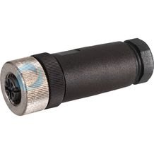
Mating connectors for sensors and valves with connector “K24”, “K35” and “K72”, M12 x 1
4P Z24
For sensors and valves with connector “K24”, “K35” and “K72” Mating connectors M12, 4-pole, line cross-section 0.75 mm2Data sheet
Spare parts & repair
Mating connectors for sensors and valves with connector “K24”, “K35” and “K72”, M12 x 1, with assembled connection line
4P Z24 +
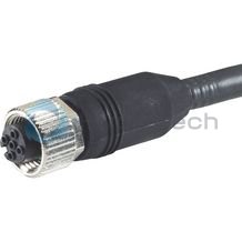
Mating connectors for sensors and valves with connector “K24”, “K35” and “K72”, M12 x 1, with assembled connection line
4P Z24 +
For sensors and valves with connector “K24”, “K35” and “K72” Mating connectors M12, 4-pole, line cross-section 0.75 mm2Data sheet
Spare parts & repair
Filter element
2.
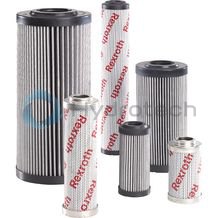
Filter element
2.
Size 0040 … 1000 Pressure differential 330 bar Filter rating 1 µm Filter area 4.8 m² Operating temperature range -10 … +100 °CData sheet
Spare parts & repair
Electronic switching elements
WE-.SP
Electronic switching elements
WE-.SP
Operating temperature -30 … +85 °CData sheet
Spare parts & repair
Electronic switching elements
WE-S02
Electronic switching elements
WE-S02
Max. operating pressure 40 bar Operating temperature -10 … +100 °CData sheet
Spare parts & repair
Pressure differential indicators for filters in pressure lines
WO-D01
Pressure differential indicators for filters in pressure lines
WO-D01
Max. operating pressure 450 bar Operating temperature -30 … +100 °CData sheet
Spare parts & repair
Seal
D245LE

Seal
D245LE
Classification according to the Pressure Equipment Directive
These inline filters for hydraulic applications according to 51421 are pressure holding equipment according to article 1, section 2.1.4 of the Pressure Equipment Directive 97/23/EC (PED). However, on the basis of the exception in article 1, section 3.6 of the PEG, hydraulic filters are exempt from the PED if they are not classified higher than category I (guideline 1/19).
For the classification, fluids from the chapter “Compatibility with permitted hydraulic fluids” have been taken into consideration.
They do not receive a CE mark.
Use in potentially explosive areas according to directive 94/9/EC (ATEX)
These inline filters according to 51421 are no equipment or components in the sense of directive 94/9/EC and are not provided with a CE mark. It has been proven with the ignition risk analysis that these inline filters do not have own ignition sources acc. to DIN EN 13463-1:2009.
According to DIN EN 60079-11:2012, the electronic maintenance indicators with one switching point:
WE-1SP-M12x1 (R928028409)
WE-1SP-EN175301-803 (R928036318)
are simple, electronic operating equipment not having an own voltage source. This simple, electronic operating equipment may - according to DIN EN 60079-14:2012 - in intrinsically safe electric circuits (Ex ib) be used in systems without marking and certification.
The inline filters and the electronic maintenance indicators described here can be used for the following potentially explosive areas:
|
Zone suitability |
||
|
Gas |
1 |
2 |
|
Dust |
21 |
22 |
Possible circuit according to DIN EN 60079-14

WARNING!
Explosion hazard due to high temperature! The temperature depends on the temperature of the medium in the hydraulic circuit and must not exceed the value specified here. Measures are to be taken so that in the explosive area, the max. admissible ignition temperature is not exceeded. When using the inline filters in accordance with 51421 in potentially explosive areas, appropriate equipotential bonding has to be ensured. The filter is preferably to be grounded via the mounting screws. It has to be noted in this connection that paintings and oxidic protective layers are not electrically conductive. During filter element exchanges, the packaging material is to be removed from the replacement element outside the explosive area