
HENGST FILTERS
1005153B
R928022355
HENGST FILTERS
MATERIAL: R928022355
SUMMARY:
Quantity in stock: 0
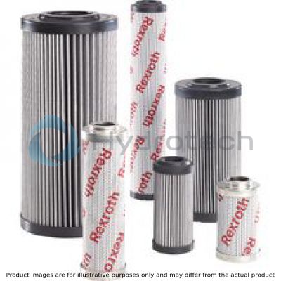
The filter element is the central component of industrial filters. The actual filtration process takes part in the filter element. The main filter variables, such as retention capacity, dirt holding capacity and pressure loss are determined by the filter elements and the filter media used in them. Rexroth filter elements are used for the filtration of hydraulic fluids in the hydraulic system as well as for the filtration of lubricants, industrial fluids and gases.
Filter elements consist of a combination of star-like pleated filter media (3) which are laid around a perforated support tube (2). In longitudinal direction, the filter element is sealed using a 2-component adhesive and support tube and filter element mat are connected with both end disks (1). Sealing between the filter element and the filter housing is effected by means of one or two seals.
Series 2.0058 and 2.0059 may optionally be selected with a bypass valve at the filter element bottom. There is generally flow from the outside to the inside.
All 2nd filter elements of the Rexroth preferred program are made of zinc-free components thus preventing the formation of zinc-soap, in particular if water-containing fluids (HFA/HFC) and synthetic oils are used.
The use of zinc-free filter elements prevents early "element blocking", thus considerably increasing the life cycle of an element.
Therefore, Rexroth filter elements can be used universally for typical hydraulic fluids and lubricants.

|
Glass fiber material, H...XL |
||||
|
Oil cleanliness class |
to be achieved with filter |
Hydraulic system |
||
|
βx(c) = 200 |
Material |
possible arrangement |
||
|
10/6/4 ‒ 14/8/6 |
1 μm |
Glass fiber material, H...XL |
Return flow or pressure filter |
Special application |
|
13/10/8 ‒ 17/13/10 |
3 μm |
Servo valves |
||
|
15/12/10 ‒ 19/14/11 |
6 μm |
High-response valves |
||
|
17/14/10 ‒ 21/16/13 |
10 μm |
Proportional valves |
||
|
19/16/12 ‒ 22/17/14 |
20 μm |
Pumps and valves in general |
||
|
Filter medium |
Oil cleanliness class |
to be achieved with filter |
Hydraulic system |
|||
|
βx(c) = 200 |
Material |
Version |
possible arrangement |
|||
|
G10 |
20/18/13 ‒ 21/20/15 |
10 μm |
Stainless steel wire mesh, G... |
Special Dutch weave |
Return flow, pressure or suction filter |
For existing systems (hydraulics) and as protective filter (G10, G25)For fluids such as:LubricantsPetrochemical productsWaterCoolants/thermal oils |
|
G25 |
Cannot be used for wire mesh > 10 µm |
25 μm |
Woven roving |
|||
|
G40 |
40 μm |
|||||
|
G60 … G800 |
60 μm … 800 μm |
Plain cloth |
||||
|
Filter medium |
Oil cleanliness class |
to be achieved with filter |
Hydraulic system |
|||
|
Filtration ratio β values 1) |
Retention rate with 10 μm 1) |
Material |
possible arrangement |
|||
|
P10 |
20/19/14 ‒ 22/20/15 |
β10(c) > 2,0 |
50 % |
Paper P... |
Return flow or pressure filter |
For existing systems |
|
P25 |
21/20/15 ‒ 22/21/16 |
β10(c) > 1,25 |
25 % |
|||
|
1) |
according to ISO 16889 |
|||||

|
|
|
Filter medium |
nominal filter rating |
|
VS25 |
25 μm |
|
VS40 |
40 μm |
|
VS60 |
60 μm |
|
Filter medium |
Oil cleanliness class |
to be achieved with filter |
Hydraulic system |
||
|
βx(c) = 75 |
Material |
possible arrangement |
|||
|
M5 |
16/13/10 ‒ 20/15/11 |
5 μm |
Metal fibre fleece M… |
Return flow or pressure filter |
Filter material for special applications |
|
M10 |
18/14/10 ‒ 21/17/13 |
10 μm |
|||
|
Filter medium |
Oil cleanliness class |
to be achieved with filter |
Hydraulic system |
||||
|
βx(c) = 200 |
Particle size βx(c) = 200 1) |
Particle size βx(c) = 1000 1) |
Material |
possible arrangement |
|||
|
AS3 |
13/10/8 ‒ 17/13/10 |
3 μm |
4,5 μm(c) |
5,0 μm(c) |
Aquasorb AS… |
Return flow, bypass or suction filter |
Servo valves |
|
AS6 |
15/12/10 ‒ 19/14/11 |
6 μm |
5,5 μm(c) |
7,5 μm(c) |
High-response valves |
||
|
AS10 |
17/14/10 ‒ 21/16/13 |
10 μm |
7,5 μm(c) |
9,5 μm(c) |
Proportional valves |
||
|
AS20 |
19/16/12 ‒ 22/17/14 |
20 μm |
20 μm(c) |
22 μm(c) |
Pumps and valves in general |
||
|
1) |
according to ISO 16889 |
||||||
Functional principleRexroth Aquasorb filter elements are pleated just like Rexroth industrial filter elements, however they contain a layer of fleece material on a water-binding fabric in the form of a fine granulate. The corresponding non-woven glass fiber media is combined behind this fleece material, depending on the filter rating. EffectivenessThe effectiveness of the Rexroth Aquasorb elements has been proven by internal testing and by a scientific examination at an independent institute. The water content (free water) can be reduced to the saturation point of the oil. The effectiveness and water absorption depend on the load on filter area, the viscosity of the oil and the oil temperature. The values of water absorption and the change at higher viscosities are specified below. Design and area of applicationRexroth Aquasorb filter elements must be dimensioned so that an initial pressure drop of 0.2 bar is not exceeded. They should be preferably used as a bypass filter in the low pressure range < 5 bar. The replacement of the filter element must be carried out at a pressure differential of at least 2.2 bar. Rexroth Aquasorb can be used only in HLP and HEES. |
|||||||
|
Aquasorb AS… |
|||||||
|
Type |
Rated flow in l/min |
calculative water absorption in ml |
|||||
|
with 15 cSt |
with 30 cSt |
with 46 cSt |
with 120 cSt |
||||
|
1.0040 |
5 |
60 |
40 |
35 |
20 |
||
|
1.0063 |
8 |
100 |
70 |
55 |
35 |
||
|
1.0100 |
14 |
160 |
110 |
90 |
60 |
||
|
1.0130 |
19 |
225 |
155 |
130 |
85 |
||
|
1.0150 |
30 |
360 |
250 |
210 |
135 |
||
|
1.0160 |
20 |
265 |
185 |
155 |
100 |
||
|
1.0250 |
32 |
435 |
305 |
255 |
165 |
||
|
1.0400 |
40 |
785 |
550 |
455 |
300 |
||
|
1.0630 |
66 |
1290 |
900 |
750 |
490 |
||
|
1.1000 |
97 |
1435 |
1005 |
830 |
545 |
||
|
1.2000 |
189 |
2785 |
1950 |
1615 |
1055 |
||
|
1.2500 |
197 |
3650 |
2555 |
2115 |
1385 |
||
|
2.0040 |
3 |
35 |
25 |
20 |
15 |
||
|
2.0063 |
5 |
55 |
40 |
30 |
20 |
||
|
2.0100 |
8 |
90 |
65 |
50 |
35 |
||
|
2.0130 |
9 |
110 |
75 |
65 |
40 |
||
|
2.0150 |
12 |
145 |
105 |
85 |
55 |
||
|
2.0160 |
17 |
200 |
140 |
115 |
75 |
||
|
2.0250 |
28 |
325 |
225 |
190 |
125 |
||
|
2.0400 |
45 |
525 |
370 |
305 |
200 |
||
|
2.0630 |
46 |
715 |
500 |
415 |
270 |
||
|
2.1000 |
73 |
835 |
585 |
485 |
315 |
||
|
2.0058 |
105 |
1545 |
1080 |
895 |
585 |
||
|
2.0059 |
121 |
1790 |
1250 |
1035 |
680 |
||
Functional principle
Rexroth Aquasorb filter elements are pleated just like Rexroth industrial filter elements, however they contain a layer of fleece material on a water-binding fabric in the form of a fine granulate. The corresponding non-woven glass fiber media is combined behind this fleece material, depending on the filter rating.
Effectiveness
The effectiveness of the Rexroth Aquasorb elements has been proven by internal testing and by a scientific examination at an independent institute. The water content (free water) can be reduced to the saturation point of the oil. The effectiveness and water absorption depend on the load on filter area, the viscosity of the oil and the oil temperature.
The values of water absorption and the change at higher viscosities are specified below.
Design and area of application
Rexroth Aquasorb filter elements must be dimensioned so that an initial pressure drop of 0.2 bar is not exceeded. They should be preferably used as a bypass filter in the low pressure range < 5 bar. The replacement of the filter element must be carried out at a pressure differential of at least 2.2 bar.
Rexroth Aquasorb can be used only in HLP and HEES.
Water absorbing, AS…
AS… Aquasorb filter elements adsorb humidity from ventilation filters as well as free water from hydraulic fluids and lubricating oils. Water can accelerate oil aging through oxidation even at low concentration above the saturation point of the oil. This results in increased corrosion and increased wear. In certain oil additives it can also cause a change or a failure in the form of solid, mucus-like substances which then prematurely clog the pores of the filter. Highly effective separation of contamination is additionally provided by its combination with glass fiber filter media.
Absolute filtration ISO 16889 with water-absorbing filter fleece Combined with non-woven glass fiber media Non-reusable filter (not cleanable due to the depth filtration effect) Pleated design: multi-layer design|
01 |
02 |
03 |
04 |
05 |
06 |
07 |
08 |
|||
|
2. |
‒ |
‒ |
0 |
‒ |
|
Design |
|||
|
01 |
Filter element |
2. 1) |
|
|
Size |
|||
|
02 |
according to BRFS standard |
0130 |
|
|
0150 |
|||
|
according to DIN 24550 |
0040 |
||
|
0063 |
|||
|
0100 |
|||
|
0160 |
|||
|
0250 |
|||
|
0400 |
|||
|
0630 |
|||
|
1000 |
|||
|
Filter rating in μm |
|||
|
03 |
Nominal |
Stainless steel wire mesh, cleanable |
G10 |
|
G25 |
|||
|
G40 |
|||
|
G60 |
|||
|
G100 |
|||
|
G200 |
|||
|
G500 |
|||
|
G800 |
|||
|
Paper, not cleanable |
P10 |
||
|
P25 |
|||
|
Fleece material, not cleanable |
VS25 |
||
|
VS40 |
|||
|
VS60 |
|||
|
Absolute |
Non-woven glass fiber media, not cleanable |
H1XL |
|
|
H3XL |
|||
|
H6XL |
|||
|
H20XL |
|||
|
Glass fiber material generation 5, non-reusable, not cleanable |
PWR10 |
||
|
Metal fibre fleece, not cleanable |
M5 |
||
|
M10 |
|||
|
Water-absorbing, not cleanable |
AS3 2) |
||
|
AS6 2) |
|||
|
AS10 2) |
|||
|
AS20 2) |
|||
|
Pressure differential |
|||
|
04 |
max. admissible pressure differential of the filter element |
30 bar |
A |
|
330 bar |
B |
||
|
Element design |
|||
|
05 |
Adhesive |
Standard adhesive |
0 |
|
Special adhesive |
H 3) |
||
|
Element design |
|||
|
06 |
Material |
Standard material |
0 |
|
Stainless steel 1.4571 |
V 4) |
||
|
Bypass valve |
|||
|
07 |
Without |
0 |
|
|
Seal |
|||
|
08 |
NBR |
M |
|
|
FKM |
V |
||
|
1) |
For the admissible temperature ranges refer to the “Technical data” |
||
|
2) |
Only configurable with pressure differential A = 30 bar |
||
|
3) |
Improved temperature and media resistance, only in connection with FKM seal |
||
|
4) |
Only in connection with special adhesive and FKM seal |
||
|
Further filter ratings and seal materials are available upon request. |
|||
general
|
Type |
2. | 2. | 2. | 2. | 2. | 2. | 2. | 2. | 2. | 2. | 2. | 2. | ||
|
Size |
0040 | 0063 | 0100 | 0160 | 0250 | 0400 | 0630 | 1000 | 0130 | 0150 | 0058 | 0059 | ||
|
Weight 1) |
m |
0.1 kg | 0.17 kg | 0.28 kg | 0.5 kg | 0.75 kg | 1.14 kg | 1.5 kg | 2.58 kg | 0.29 kg | 0.32 kg | 3.4 kg | 3.8 kg | |
|
Filter rating / mesh size |
1 µm | |||||||||||||
|
Filter area |
4.8 m² | |||||||||||||
|
Ambient temperature range |
-10 … +65 °C | |||||||||||||
|
Operating temperature range |
-10 … +100 °C | |||||||||||||
|
Storage temperature range 2) |
NBR |
-40 ... +65 °C | ||||||||||||
|
Storage temperature range 2) |
FKM |
-20 ... +65 °C | ||||||||||||
|
Material |
Cover of the filter element |
Polyamide or tin-coated steel or tin-coated aluminum | ||||||||||||
|
Base of the filter element |
Polyamide or tin-coated steel or tin-coated aluminum | |||||||||||||
|
Support tube of the filter element |
Tin-coated steel | |||||||||||||
|
Seals |
NBR / FKM | |||||||||||||
| 1) | refers to non-woven glass fiber media |
| 2) | max. relative air humidity 65 % |
hydraulic
|
Size |
0040 | 0063 | 0100 | 0160 | 0250 | 0400 | 0630 | 1000 | 0130 | 0150 | 0058 | 0059 |
|
Filtration direction |
From the outside to the inside | |||||||||||
|
Maximum pressure differential |
330 bar | |||||||||||
|
Minimum conductivity of the medium |
300 pS/m | |||||||||||
|
Hydraulic fluid temperature range |
-10 … +100 °C | |||||||||||
Important information on hydraulic fluids!
For more information and data on the use of other hydraulic fluids, please refer to data sheet 90220 or contact us! Flame-resistant – containing water: Due to possible chemical reactions with materials or surface coatings of machine and system components, the service life with these hydraulic fluids may be less than expected. Filter materials made of filter paper P must not be used, filter elements with glass fiber material have to be used instead. Bio-degradable: If filter materials made of filter paper are used, the filter life may be shorter than expected due to material incompatibility and swelling.For applications outside these parameters, please consult us!
|
Hydraulic fluid |
Classification |
Suitable sealing materials |
Suitable adhesive |
Standards |
|
|
Mineral oil |
HLP |
NBR |
Standard |
DIN 51424 |
|
|
Bio-degradable |
Insoluble in water |
HETG |
NBR |
VDMA 24568 |
|
|
HEES |
FKM |
||||
|
Soluble in water |
HEPG |
FKM |
VDMA 24568 |
||
|
Flame-resistant |
Water-free |
HFDU, HFDR |
FKM |
VDMA 24317 |
|
|
Containing water |
HFAS |
NBR |
DIN 24320 |
||
|
HFAE |
NBR |
||||
|
HFC |
NBR |
VDMA 24317 |
|||
|
Skydrol |
‒ |
EPDM |
Special “H” |
‒ |
|
|
Attainable filtration ratio βx(c) (β value) |
|||
|
Typical β values of up to 2.2 barΔp pressure increase at the filter element 1) |
|||
|
Filter medium |
Particle size “x” for different β values, measurement according to ISO 16889 |
||
|
βx(c) ≤ 75 |
βx(c) ≤ 200 |
βx(c) ≤ 1000 |
|
|
H1XL |
< 4,0 μm(c) |
< 4,0 μm(c) |
< 4,0 μm(c) |
|
H3XL |
4,0 μm(c) |
< 4,5 μm(c) |
5,0 μm(c) |
|
H6XL |
4,8 μm(c) |
5,5 μm(c) |
7,5 μm(c) |
|
H10XL |
6,5 μm(c) |
7,5 μm(c) |
9,5 μm(c) |
|
H20XL |
18,5 μm(c) |
20,0 μm(c) |
22,0 μm(c) |
|
1) |
Filtration ratio βx(c) for other filter media upon request |
||
Filtration ratio ßx(c) dependent on particle size μm(c)

Dirt holding capacity
Compared to conventional filter media with single layer technology, the H...XL filter material features a high dirt holding capacity because it is made of two separate filter layers connected in series.
Superior dirt holding capacity of H...XL filter elements

When has the filter element to be replaced or cleaned~^&@@&^~
As soon as the dynamic pressure or the pressure differential set at the maintenance indicator is reached, the red pushbutton of the mechanical/visual maintenance indicator pops out. If an electronic switching element is provided, an electric signal will moreover sound. In this case, the filter element must be replaced or cleaned.
If the filter does not have a maintenance indicator, we recommend exchanging or cleaning filter elements after a maximum of six months.
Filter element exchange
For single filters: Switch off the system and discharge the filter on the pressure side. For installed duplex switch filters: Refer to the relevant maintenance instructions according to the filter type.Detailed instructions with regard to the filter element exchange can be found on the data sheet of the relevant filter series.
Warning:
Filters are containers under pressure. Before opening the filter housing, check whether the system pressure in the filter has been decreased to ambient pressure. Only then may the filter housing be opened for maintenance.
Notice:
Due to the high viscosity, the pre-set signal value of the visual maintenance indicator may be exceeded during cold start. After the operating temperature has been reached, the mechanical/visual indicator can be acknowledged manually. The electrical signal will go out after the operating temperature has been reached. If the maintenance indicator signal is ignored, the disproportionately increasing pressure differential may damage the filter element causing it to collapse. Warranty becomes void if the delivered item is changed by the ordering party or third parties or improperly mounted, installed, maintained, repaired, used or exposed to environmental condition that do not comply with the installation conditions.G…
Cleaning or replacement
Before cleaning a G... element, the filter element has to be dismantled first and then checked whether it makes sense to clean the element. For example, if the cloth contains many fibrous substances and consists of a material finer than G40, effective and complete cleaning is not possible in many cases. Filter mesh which has visible defects due to frequent cleaning must be replaced. In general, the following applies: The finer the cloth, the thinner the wire. Therefore, especially fine mesh must be cleaned gently to protect the material. Cracks in the folds of the wire mesh and the metal fiber fleece are to be avoided. Otherwise, the filter capacity will be insufficient.
Cleaning frequency
Experience has shown that filter elements made of G10, G25 and G40 can be cleaned up to ten times.
Filter mesh > 60 μm can usually be cleaned more than ten times. Reusability, however, very much depends on the type of contamination as well as on pressurisation (final Δp before dismantling the filter element). For maximum reusability, we therefore recommend exchanging in particular the fine mesh at a final Δp of 2.2 bar at the latest. Due to the given reasons, the aforementioned values must be regarded as reference values for which we do not assume any liability.
|
Manual and simple cleaning method for filter elements made of wire mesh |
||
|
Procedure |
Wire mesh G10, G25, G40 |
Wire mesh G60 and larger |
|
Chemical pre-cleaning |
Let the filter element drain for approx. 1 hour after disassembly. Bathe in solvent afterwards. |
|
|
Mechanical pre-cleaning |
Remove rough dirt with a brush or scrubber. Do not use hard or pointed objects which could damage the filter medium. |
|
|
Mechanical/chemical main cleaning |
Put pre-cleaned element in an ultrasonic bath with special solvent. Clean the element in the ultrasonic bath until any visible contamination is removed. |
Evaporate with hot washing solution (water with corrosion protection agent) |
|
Test |
Visually check the material for damage. Replace the filter element if you identify obvious damage. |
|
|
Preservation |
After drying, you must spray the cleaned element with preservative agents and store it sealed against dust in a plastic foil. |
|
|
Automated cleaning method for filter elements made of wire mesh |
|
|
Procedure |
Wire mesh G10 ... G800 |
|
Chemical pre-cleaning |
Let the filter element drain for approx. 1 hour after disassembly. Bathe in solvent afterwards. |
|
Mechanical/chemical main cleaning |
By means of special cleaning systems for filter elements. Most of these systems are provided with a fully automated and combined cleaning mechanism including ultrasound as well as mechanical and chemical cleaning processes. This allows for best possible cleaning results with gentle cleaning processes. |
Filter variables
Filter rating and attainable oil cleanliness
The main goal when using industrial filters is not only the direct protection of machine components but to attain the required oil cleanliness.
Oil cleanliness is defined on the basis of oil cleanliness classes which classify how the amount of particles of the existing contamination is distributed in the operating liquid.
Filtration performance
Filtration ratio ßx(c) (ß value)
The retention capacity of hydraulic filters with regard to the contamination in a hydraulic system is characterized by the filtration ratio βx(c). This variable is therefore the most important performance characteristic of a hydraulic filter. It is measured in the multipass test, and is the average value of the specified initial and final pressure differential according to ISO 16889 using ISOMTD test dust.
The filtration ratio βx(c) is defined as the ratio of the particle count of the respective particle size on both sides of the filter.
Dirt holding capacity
It is also measured using the multipass test and determines the amount of test dust ISOMTD which is fed to the filter medium until a certain pressure differential increase has been reached.
Pressure loss (also pressure differential or delta p)
The pressure loss of the filter element is the relevant characteristic value for the determination of the filter size. These are recommended values of the filter manufacturer or specifications by the filter user. This characteristic value depends on many factors. Mainly: the rating of the filter medium, its geometry and arrangement in the filter element, the filter area, the operating viscosity of the fluid and the flow.
The term “delta p” is often also expressed with the symbol: “Δp”.
When dimensioning the complete filter with filter element, an initial pressure loss is determined which must not be exceeded by the new filter element state on the basis of the aforementioned conditions. The size design of a Rexroth filter element and new complete filter by means of initial Δp or pressure loss may be comfortably completed using our online design software “BOSCH REXROTH FILTERSELECT”.
The following diagram shows the typical press loss behavior of filter elements with different material fineness at different flows for a viscosity of 30 mm2/s.

The diagram shows the typical pressure loss behaviour of filter elements with different filter media at different flow rates.
|
Admissible operating temperature range depends on the combination of materials. |
||
|
Material |
Ordering code |
Operating temperature range in °C |
|
Seal |
||
|
NBR |
M |
-40…+100 |
|
FKM |
V |
-20…+210 |
|
Element design |
Adhesive |
|
|
Standard |
0 |
-40…+100 |
|
Special adhesive |
H |
-55…+170 |
|
Element design |
Material |
|
|
Standard |
0 |
-40…+100 |
|
Stainless steel |
V |
-55…+170 |
|
Filter element |
Material |
|
|
Aquasorb |
AS… |
0…+160 |
|
Stainless steel wire mesh |
G… |
-55…+500 |
|
Non-woven glass fiber media, not cleanable |
H…XL |
…+160 |
|
Metal fibre fleece |
M… |
-55…+250 |
|
Filter paper |
P… |
…+130 |
|
Fleece material |
VS… |
…+80 |
Rexroth filter elements are tested and quality-monitored according to different ISO test standards:
Filtration performance test (multipass test): ISO 16889:2008-06
Δp (pressure loss) characteristic curves: ISO 3968:2001-12
Compatibility with hydraulic fluid: ISO 2943:1998-11
Collapse pressure test: ISO 2941:2009-04
The development, manufacture and assembly of Rexroth industrial filters and Rexroth filter elements is carried out within the framework of a certified quality management system in accordance with ISO 9001:2000.
Environmental safety and recycling
The used filter element should be disposed of in accordance with the respective country-specific legal regulations of environmental protection.
After completion of the filter life, the components of the filter, in accordance with the respective country-specific legal regulations of environmental protection, are recycled.