
HENGST FILTERS
1004708B
R928019168
HENGST FILTERS
MATERIAL: R928019168
SUMMARY:
Quantity in stock: 0
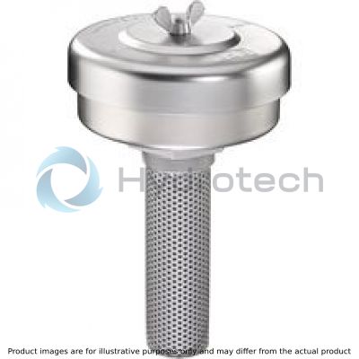
Function, section
The tank breathing filter guarantees air exchange in the fluid tank. Depending on the machine cycles, air can be pulled into the tank with contamination when a breather filter is not used. A tank breather filter will accomplish both the
pressure equalization and air filtration preventing contamination from entering the tank through the air exchange.
It basically consists of a threaded cover (1), a filter element (2) and a bottom housing (3) to accommodate the filter element.
The contaminated air is transported through the filter element into the hydraulic tank (T) via the opening (A). Only filtered air enters the tank. Escaping air is also directed through the filter element.
Version TLF I 7-125 and 8-250
All sizes have a flange.
Version TLF III 7-125
All sizes have a flange. Version III also has a 130 μm filling strainer (4).
When air humidity is high or when there are large temperature variations, the exchanged air may condense and promote the oxidation process of the oil. This leads to corrosion and damage to the fluid tank.
In this case, we recommend use of our “AS10” waterabsorbent filter material to dry the incoming air.

|
01 |
02 |
03 |
04 |
05 |
06 |
07 |
08 |
09 |
10 |
11 |
12 |
|||
|
TLF |
‒ |
S00 |
‒ |
0 |
0 |
0 |
‒ |
00 |
0 |
0 |
|
Series |
|||||
|
01 |
Tank breathing filter |
TLF |
|||
|
Connection |
|||||
|
02 |
DIN flange |
I |
|||
|
DIN flange |
III |
||||
|
Size |
|||||
|
03 |
TLF I; TLF III |
7-125 |
|||
|
TLF I |
8-250 |
||||
|
Filter rating in μm |
|||||
|
04 |
Absolute |
Glass fiber material, not cleanable |
Air retention, ASHRAE 52.1, test dust SAE fine: 95% for particles > 0,3 μm |
H10XL |
|
|
Nominal |
Filter paper, not cleanable |
Air retention, ASHRAE 52.1, test dust SAE fine: 95% for particles > 1,24 μm |
P10 |
||
|
Pressure differential |
|||||
|
05 |
Max. admissible pressure differential of the filter element 1 bar |
S00 |
|||
|
Solenoid |
|||||
|
06 |
Without |
0 |
|||
|
Valve |
|||||
|
07 |
Without |
0 |
|||
|
Maintenance indicator |
|||||
|
08 |
Without |
0 |
|||
|
Connection |
|||||
|
09 |
Frame size |
7-125 |
8-250 |
00 |
|
|
Connection |
DIN 2573 DN125 |
DIN 2573 DN250 |
|||
|
Seal |
|||||
|
10 |
NBR seal |
M |
|||
|
FKM seal |
V |
||||
|
Material |
|||||
|
11 |
Standard |
0 |
|||
|
Supplementary information |
|||||
|
12 |
Without |
0 |
|||
General
|
Type |
TLF I | TLF III | |||
|
Size |
7-125 | 8-250 | 7-125 | ||
|
Installation position |
Tank mounted filters | ||||
|
Connection |
Standard |
DIN 2573 DN125 | DIN 2573 DN250 | DIN 2573 DN125 | |
|
Operating temperature range |
°C |
-40 … +100 | |||
|
Ambient temperature range |
°C |
-40 … +65 | |||
|
Storage conditions 1) |
Seal |
°C |
-40 ... +65 | ||
|
Seal FKM |
°C |
-20 ... +65 | |||
|
Material |
Filter cover |
Tin-coated steel | |||
|
Seals |
NBR / FKM | ||||
|
Filter bottom |
Tin-coated steel | ||||
|
Filling strainer |
Stainless steel / aluminium | ||||
|
Weight |
kg |
11.4 | 51 | 11.6 | |
| 1) | max. relative air humidity 65 % |
For applications outside these parameters, please consult us!
Compatibility with permitted hydraulic fluids
|
TLF II; TLF III |
||||
|
Hydraulic fluid |
Classification |
Suitable sealing materials |
Standards |
|
|
Mineral oil |
HLP |
NBR |
DIN 51524 |
|
|
Other hydraulic fluids upon request. |
||||
|
TLF I |
||||
|
Hydraulic fluid |
Classification |
Suitable sealing materials |
Standards |
|
|
Mineral oil |
HLP |
NBR |
DIN 51524 |
|
|
Bio-degradable |
Insoluble in water |
HETG |
NBR |
VDMA 24568 |
|
HEES |
FKM |
|||
|
Soluble in water |
HEPG |
FKM |
VDMA 24568 |
|
|
Flame-resistant |
Water-free |
HFDU, HFDR |
FKM |
VDMA 24317 |
|
Containing water |
HFAS |
NBR |
DIN 24320 |
|
|
HFAE |
NBR |
|||
|
HFC |
NBR |
VDMA 24317 |
||
Important information on hydraulic fluids:For more information and data on the use of other hydraulic fluids, please refer to data sheet 90220 or contact us.
• Flame-resistant - containing water: due to possible chemical reactions with materials or surface coatings of machine and system components, the service life with these hydraulic fluids may be less than expected. Filter materials made of filter paper (cellulose) must not be used, filter elements with glass fiber material must be used instead.
• Bio-degradable: If filter materials made of filter paper are used, the filter life may be shorter than expected due to material incompatibility and swelling. |
||||
measured at test temperature = 20 °C
TLF...7-125

TLF...8-250


TLF I 7-125, 8-250
Dimensions in mm

TLF III 7-125

|
Type |
A1 |
A2 |
A3 |
A4 |
A5 |
⌀B1 |
⌀B2 |
⌀B3 |
⌀B5 |
⌀B6 |
C1 |
|
mm |
mm |
mm |
mm |
mm |
mm |
mm |
mm |
mm |
mm |
||
| TLF I 7-125 | 263 | 154 | 85 | 36 | 20 | 350 | 300 | 375 | 130 | 200 | 8x ⌀18 |
| TLF I 8-250 | 734 | 620 | 402 | 37.5 | 24 | 502 | 419 | 253 | 335 | 12x ⌀18 | |
| TLF III 7-125 | 263 | 154 | 85 | 36 | 20 | 350 | 300 | 240 | 130 | 200 | 8x ⌀18 |
Assembly, commissioning, maintenance
Assembly
The filter connection must correspond to the tank connection. If the size is TLF ... 7 or TLF I 8 version is used (version with DIN flanges), the hole pattern (DIN 2573) of the tank must be compared to the dimensions from the “Dimensions” chapter prior to installation. Install the filter on the tank. When installing the filter, the required servicing height of the replacement filter must be taken into account. For servicing reasons, we recommend installing the filter in a vertical position. All filter components must be tightened manually.
Commissioning
It is not necessary to commission the filter.
Maintenance
Exchange of the filter element
No maintenance indicator is provided, but the filter element must be changed at minimum every 6 months. Since the ambient conditions are very different depending on the place of installation, we recommend considering more frequent replacement of the filter element according to the specific installation conditions for TLF tank breathing filters.
Notice:
Vacuum switch (upon request) for monitoring the suction pressure can be mounted on the tank separately.
Warning!
The filter must not be operated without a filter element
Notes:
All work on the filter must be performed by trained specialists. Proper function and safety are only guaranteed if original Bosch Rexroth filter elements and spare parts are used. Warranty becomes void if the delivered item is changed by the ordering party or third parties or improperly mounted, installed, maintained, repaired, used or exposed to environmental condition that do not comply with the installation conditions.Tightening torques MA in Nm for screw-in cartridge valves
|
Series |
TLF I 7-125 und 8-250; TLF III 7-125 |
|
|
Breathing filter Tightening torque with μtotal = 0.14 |
Nm [lbf-ft] |
80 ± 8 [59 ± 5.9] |
|
Wing nut |
Tighten by hand |
|
Directives and standardization
Classification according to the Pressure Equipment Directive
Off-line tank breathing filters according to 51415 are not classified as devices or components for the purpose of the Pressure Equipment Directive 97/23/EC (PED).
Directive 94/9/EC (ATEX)
According to the assessment of the risk of ignition, the tank breathing filters must not be used in explosive areas.
Filter element
7.
Filter element
7.
Size 002 … 008 Pressure differential 1 bar Filter rating 1 µm Operating temperature range -10 … +100 °CData sheet
Spare parts & repair