
HENGST FILTERS
1001992B
R928001331
HENGST FILTERS
MATERIAL: R928001331
SUMMARY:
Quantity in stock: 0
|
01 |
02 |
03 |
04 |
05 |
06 |
07 |
08 |
09 |
10 |
11 |
12 |
|||
|
16FD |
‒ |
A |
‒ |
0 |
V2,2 |
‒ |
D0 |
0 |
|
Series |
|||
|
01 |
Duplex filter, 16 bar |
16FD |
|
|
Size |
|||
|
02 |
2500 |
||
|
3000 |
|||
|
4000 |
|||
|
6000 |
|||
|
7000 |
|||
|
7500 |
|||
|
Filter rating in μm |
|||
|
03 |
Nominal |
Stainless steel wire mesh, cleanable |
G10 |
|
G25 |
|||
|
G40 |
|||
|
G100 |
|||
|
Paper, not cleanable |
P10 |
||
|
Absolute |
Non-woven glass fiber media, not cleanable |
H3XL |
|
|
H20XL |
|||
|
Glass fiber material generation 5, non-reusable, not cleanable |
PWR10 |
||
|
Pressure differential |
|||
|
04 |
max. admissible pressure differential of the filter element |
30 bar |
A |
|
Element design |
|||
|
05 |
Standard adhesive T = 100 °C |
0… |
|
|
Special adhesive T = 200 °C |
E… |
||
|
Standard material |
…0 |
||
|
chemically nickel-plated |
…D1) |
||
|
Solenoid |
|||
|
06 |
Without |
0 |
|
|
Bypass valve |
|||
|
07 |
Without |
0 |
|
|
3.0 bar |
Standard |
6 |
|
|
Maintenance indicator |
|||
|
08 |
Maintenance indicator, mech./visual, switching pressure 2.2 bar |
V2,2 |
|
|
Connection |
|||
|
09 |
DIN flange |
D0 |
|
|
Seal |
|||
|
10 |
NBR |
M |
|
|
FKM |
V |
||
|
Material |
|||
|
11 |
Standard |
0 |
|
|
Supplementary information |
|||
|
12 |
Pressure equalization line |
Standard |
A |
|
with cover lift-off device |
M |
||
|
Manufacturer's inspection certificate M according to DIN 55350 T18 |
Z |
||
|
1) |
Only in connection with FKM seal |
||
|
Hydraulic fluid |
Classification |
Suitable sealing materials |
Suitable adhesive |
Standards |
|
|
Mineral oil |
HLP |
NBR |
Standard |
DIN 51424 |
|
|
Bio-degradable |
Insoluble in water |
HETG |
NBR |
VDMA 24568 |
|
|
HEES |
FKM |
||||
|
Soluble in water |
HEPG |
FKM |
VDMA 24568 |
||
|
Flame-resistant |
Water-free |
HFDU, HFDR |
FKM |
VDMA 24317 |
|
|
Containing water |
HFAS |
NBR |
DIN 24320 |
||
|
HFAE |
NBR |
||||
|
HFC |
NBR |
VDMA 24317 |
|||
|
Skydrol |
‒ |
EPDM |
Special “H” |
‒ |
|
General
|
Size |
2500 | 3000 | 4000 | 6000 | 7000 | 7500 | ||
|
Weight |
Filter |
kg |
285 | 325 | 420 | 505 | 995 | 1210 |
|
Volume |
l |
2x64 | 2x70 | 2x99 | 2x178 | 2x395 | 2x412 | |
|
Material |
Filter cover |
Steel, stainless steel | ||||||
|
Filter housing |
Steel, stainless steel | |||||||
|
Seals |
NBR / FKM | |||||||
Important information on hydraulic fluids!
For more information and data on the use of other hydraulic fluids, please refer to data sheet 90220 or contact us! Flame-resistant – containing water: Due to possible chemical reactions with materials or surface coatings of machine and system components, the service life with these hydraulic fluids may be less than expected. Filter materials made of filter paper P must not be used, filter elements with glass fiber material have to be used instead. Bio-degradable: If filter materials made of filter paper are used, the filter life may be shorter than expected due to material incompatibility and swelling.hydraulic
|
Size |
2500 | 3000 | 4000 | 6000 | 7000 | 7500 | ||
|
Operating pressure |
pmax |
bar |
16 | |||||
|
Flow, max. |
l/min |
2650 | 3500 | 3900 | 6400 | 8700 | 12000 | |
For applications outside these parameters, please consult us!
Filter element (measured with mineral oil HLP46 according to DIN 51524)
Spec. weight: < 0.9 kg/dm3
Δp-Q characteristic curves for complete filter, recommended initial Δp for design = 0.5 bar
Selection of the perfect filter is made possible by our online “Bosch Rexroth FilterSelect“ design software.
16FD2500-H3XL

16FD3000-H3XL

16FD4000-H3XL

16FD6000-H3XL

16FD7000-H3XL

16FD7500-H3XL

16FD2500-H10XL

16FD3000-H10XL

16FD4000-H10XL

16FD6000-H10XL

16FD7000-H10XL

16FD7500-H10XL

16FD2500-H20XL

16FD3000-H20XL

16FD4000-H20XL

16FD6000-H20XL

16FD7000-H20XL

16FD7500-H20XL


Installation
Compare the operating pressure with name plate information.
Install the filter in the pipeline; observe the flow direction (direction arrows).
Notice:
Tank is under pressure!
Assembly and disassembly only with depressurized system!
Leave the pressure compensation with opened filter closed (vertical lever position)!
Do not operate the switch-over with opened filter!
Do not exchange the maintenance indicator and the pressure compensation while the filter is under pressure!
Functional and safety warranty only applicable when using genuine Rexroth spare parts!
Maintenance only be trained personnel!
Bring the switching lever into central position in order to fill both filter sides.
Switch on system pump. Pressure compensation is open. Bleed filter by opening the bleed screw; close when operating medium escapes. Close the pressure compensation.
Switch the filter into the operating position. The switching lever must rest against the stop. The pressure compensation remains closed.
If at operating temperature, the red indicator pin reaches out of the maintenance indicator item 5 to the stop to the plastic cap and/or if the switching process in the electronic indicator is triggered, the filter element is contaminated and needs to be replaced and cleaned respectively.
Open the pressure compensation. Switch over the switching lever in the opposite direction to the stop to the clean filter side. Close the pressure compensation. Reduce the operating pressure at the decommissioned filter by opening the bleed screw. Lift off the filter cover. Open the plug screws at the filter housing and empty the filter. Remove the filter elements from the lower spigots in the filter housing by rotating them slightly.
Check the filter housing for cleanliness and clean it if necessary.
Renew filter element H...-XL and P10. Clean the filter element with material G....
Re-install cleaned or replaced filter elements in the filter housing. Check the seal, renew in case of damage or wear. Re-attach the filter cover. Open the pressure compensation. Bleed filter by opening the bleed screw; close when operating medium escapes. Close the pressure compensation.
Technical modifications reserved!
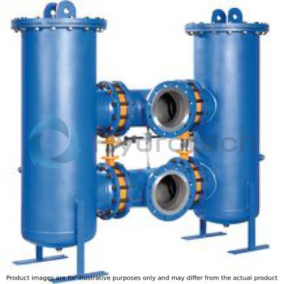
Welded steel construction consisting of two filter housings that are connected to each other by means of four shut-off flaps as switching unit. The connections are located above each other. Filter cover with bleeding and filter housing with drain screws.
Materials see spare part list.
Further design variants are available upon request.
Filter element
Pleated design with optimized pleat density and various filter materials.
The filter element is the most important component of the “FILTER” system with regard to the availability and the wear protection of the systems.
Decisive criteria for the selection comprise the necessary cleanliness of the operating medium, the initial pressure differential and the dirt holding capacity.
More detailed information is contained in our “Filter elements” prospectus.
Bypass valve
For protection of the filter element during cold start and exceedance of the pressure differential as a consequence of contamination.
|
Position |
Quantity |
Denomination |
Material |
|||||||
|
Steel |
Stainless steel |
2500 |
3000 |
4000 |
6000 |
7000 |
7500 |
|||
|
1 |
2 |
Filter housing |
St |
Stainless steel 1.4571 |
Indicate ordering information “Filter" |
|||||
|
2 |
2 |
Filter cover |
St |
Stainless steel 1.4571 |
Indicate ordering information “Filter" |
|||||
|
3 |
1 |
Filter element kit |
Various |
Various |
Indicate ordering information “Filter element" |
|||||
|
2 x 3 |
2 x 4 |
2 x 6 |
2 x 10 |
|||||||
|
Individual elements |
Individual elements |
|||||||||
|
3.1 |
1 |
Seal kit |
NBR / FKM |
Indicate ordering information “Filter" |
||||||
|
4 |
1 |
Seal ring |
NBR / FKM |
Indicate ordering information “Filter" |
||||||
|
5 |
2 |
Bleed screw |
Stainless steel 1.4571 / FKM |
Parts no. 13284 |
||||||
|
6 |
2 |
Shutoff valve |
Various |
Indicate ordering information “Filter" |
||||||
|
7 |
1 |
Maintenance indicator |
Various |
See ordering information “Maintenance indicator" |
||||||
|
8 |
1 |
Pressure equalization line |
Various |
Indicate ordering information “Filter" |
||||||
|
9 |
4 |
Plug screw |
5.8 |
Stainless steel A4 |
Parts no. 791 Parts no. 3485 for “stainless steel” version |
|||||
|
10 |
4 |
Seal ring |
Soft iron |
Stainless steel A4 |
Parts no. 335 Parts no. 3752 for “stainless steel” version |
|||||
|
All part no. BRFS-specific. |
||||||||||
Maintenance indicator
Basically, the filter is equipped with mechanical optical maintenance indicator. The electronic maintenance indicator is connected via the electronic switching element with 1 or 2 switching points, which has to be ordered separately. The electronic switching element is attached to the mechanical optical maintenance indicator and held by means of a locking ring.
Bleed valve
For bleeding the filter in the commissioning and for the safe reduction of the operating pressure.
Electronic switching elements
WE-.SP
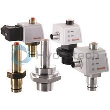
Electronic switching elements
WE-.SP
Operating temperature -30 … +85 °CData sheet
Spare parts & repair
Electronic switching elements
WE-S02
Electronic switching elements
WE-S02
Max. operating pressure 40 bar Operating temperature -10 … +100 °CData sheet
Spare parts & repair
Pressure differential indicators for filters in pressure lines
WO-D01
Pressure differential indicators for filters in pressure lines
WO-D01
Max. operating pressure 450 bar Operating temperature -30 … +100 °CData sheet
Spare parts & repair
Environmental safety and recycling
The used filter element should be disposed of in accordance with the respective country-specific legal regulations of environmental protection.
After completion of the filter life, the components of the filter, in accordance with the respective country-specific legal regulations of environmental protection, are recycled.