
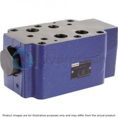
BOSCH REXROTH
Z2S22A1-5X/
R900433032
Check Valves
Check valves: Z2S 22.-5x/
BOSCH REXROTH
MATERIAL: R900433032
SUMMARY: Check valves: Z2S 22.-5x/
Quantity in stock: 0
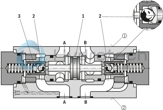
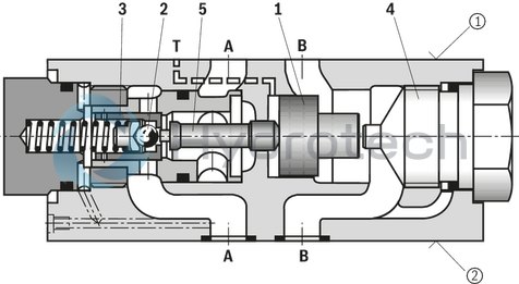
The isolator valve type Z2S is a releasable check valve in sandwich plate design.
It is used for the leakage-free blocking of one or two actuator ports, also in case of longer standstill times.
In direction A① to A② or B① to B②, there is a free flow; in the opposite direction, the flow is blocked.
If, for example, there is a flow through the valve in direction A① to A②, the control spool (1) is moved in the direction of the B side, opens the ball seat valve (2) and then pushes the poppet (3) off its seat. Hydraulic fluid can now flow from B➁ to B➀.
In order to allow the ball seat valve (2) to be safely closed, the control spool (1) must be hydraulically unloaded (see circuit example).
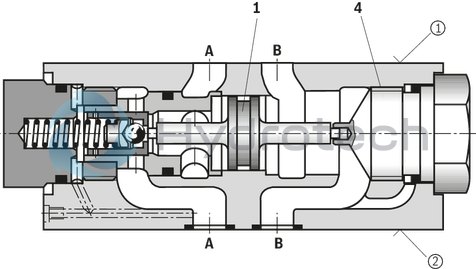
Pre-opening
Due to the pre-opening, there is a damped decompression of the pressurized liquid. Thus, possible switching shocks are avoided. The two-stage set-up with an increased control open ratio means even low pilot pressure can be unloaded securely.Type Z2S 22 ‒…
Type Z2S 22 A…
Type Z2S 22 ‒…SO40
Type Z2S 22 A…SO60
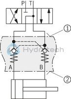
Circuit example, schematic
|
1 |
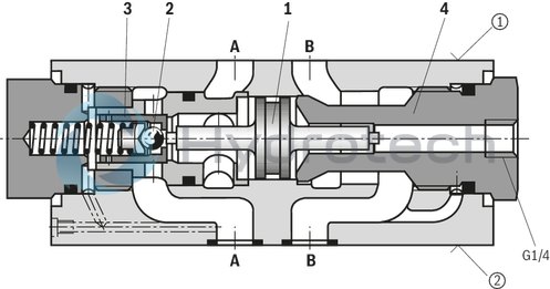
Control spool, area A2 |
|
2 |
Ball, area A3 |
|
3 |
Poppet, area A1 |
|
4 |
Stop |
|
5 |
Control spool, area A4 |
|
① |
component side |
|
② |
plate side |
|
01 |
02 |
03 |
04 |
05 |
06 |
07 |
08 |
09 |
||
|
Z2S |
22 |
– |
5X |
/ |
* |
|
01 |
Check valve, Sandwich plate design |
Z2S |
|
02 |
Size 25 |
22 |
|
Leakage-free blocking |
||
|
03 |
Channel A and B |
– |
|
Channel A |
A |
|
|
Channel B |
B |
|
|
Cracking pressure |
||
|
04 |
3 bar |
1 |
|
5 bar |
2 |
|
|
7,5 bar |
3 |
|
|
10 bar |
4 |
|
|
05 |
Component series 50 ... 59 (50 ... 59: unchanged technical data and pin assignment) |
5X |
|
06 |
Surface without corrosion resistance 1) |
no code |
|
Seal material |
||
|
07 |
NBR seals |
no code |
|
FKM seals |
V |
|
|
Observe compatibility of seals with hydraulic fluid used. |
||
|
Special version |
||
|
08 |
Without |
no code |
|
Control open by external port G1/4 (only version "A" and "B") |
SO40 |
|
|
Control spool unloaded to port T |
SO60 |
|
|
09 |
Further details in the plain text |
* |
| 1) | Corrosion-resistant surface on request: e.g. "J50" thick film passivated (DIN 50979 Fe//Zn8//Cn//To) |
general
|
Size |
25 | ||
|
Weight |
kg |
12 | |
|
Installation position |
any | ||
|
Ambient temperature range |
NBR seals |
°C |
-30 … +80 |
|
FKM seals |
°C |
-20 … +80 | |
hydraulic
|
Size |
25 | ||
|
Maximum operating pressure |
bar |
315 | |
|
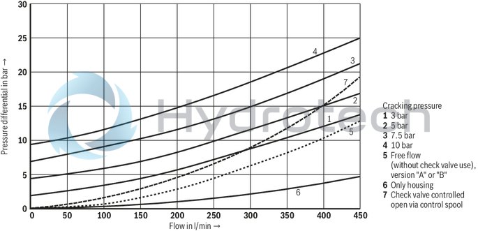
Cracking pressure (in free direction) |
3 / 5 / 7.5 / 10 bar | ||
|
Maximum flow |
l/min |
450 | |
|
Direction of flow |
see symbols | ||
|
Hydraulic fluid |
see table "Hydraulic fluid" | ||
|
Hydraulic fluid temperature range |
NBR seals |
°C |
-30 … +80 |
|
FKM seals |
°C |
-20 … +80 | |
|
Viscosity range |
mm²/s |
2.8 … 500 | |
|
Maximum admissible degree of contamination of the hydraulic fluid, cleanliness class according to ISO 4406 (c) 1) |
Class 20/18/15 | ||
|
Area ratio |
With pre-opening |
A3/A2 ~ 1/12.5 (see sectional drawing) | |
|
Version "SO60" |
A1/A4 ~ 1/9 (see sectional drawing) | ||
| 1) | The cleanliness classes specified for the components must be adhered to in hydraulic systems. Effective filtration prevents faults and simultaneously increases the life cycle of the components. For the selection of the filters, see www.boschrexroth.com/filter. |
|
Hydraulic fluid |
Classification |
Suitable sealing materials |
Standards |
Data sheet |
|
|
Mineral oils |
HL, HLP, HLPD, HVLP, HVLPD |
NBR, FKM |
DIN 51524 |
90220 |
|
|
Bio-degradable |
Insoluble in water |
HETG |
NBR, FKM |
ISO 15380 |
90221 |
|
HEES |
FKM |
||||
|
Soluble in water |
HEPG |
FKM |
ISO 15380 |
||
|
Flame-resistant |
Water-free |
HFDU |
FKM |
ISO 12922 |
90222 |
|
HFDR |
FKM |
||||
|
Containing water |
HFC (Fuchs Hydrotherm 46M, Petrofer Ultra Safe 620) |
NBR |
ISO 12922 |
90223 |
|
|
Important information on hydraulic fluids: For more information and data on the use of other hydraulicfluids, please refer to the data sheets above or contact us. There may be limitations regarding the technical valve data (temperature, pressure range, life cycle, maintenance intervals, etc.). The ignition temperature of the hydraulic fluid used must be 50 K higher than the maximum surface temperature. Flame-resistant - containing water: Maximum pressure differential per control edge 50 bar Pressure pre-loading at the tank port > 20 % of the pressure differential, otherwise increased cavitation Life cycle as compared to operation with mineral oil HL, HLP 50 … 100%. Bio-degradable and flame-resistant – containing water: If this hydraulic fluid is used, small amounts of dissolved zinc may get into the hydraulic system. |
|||||
For applications outside these parameters, please consult us!
(measured with HLP46, ϑOil = 40 ±5 °C)
Δp-qV characteristic curves
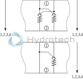
|
① |
component side |
|
② |
plate side |
Examples
Version "A"

Version "-"

Version "B"

Version "A…SO40"

Version "A…SO60"

Dimensions in mm
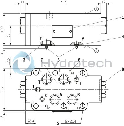
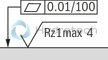 |
|
Required surface quality of the valve contact surface |
|
① |
component side |
|
② |
plate side |
|
1 |
Name plate |
|
2 |
Through holes for valve mounting |
|
3 |
Identical seal rings for ports A, B, P, and T |
|
4 |
Identical seal rings for ports X, Y, L |
|
5 |
Locking pins |
|
6 |
Locating holes |
|
7 |
Porting pattern according to ISO 4401-08-08-0-05 |
|
8 |
Plug screw SW46, tightening torque MA = 70 Nm |
|
Type |
Cracking pressure |
Leakage-free blocking in channel |
L1 in mm |
L2 in mm |
|
"no code" |
1 + 2 |
"–" |
14 |
14 |
|
3 + 4 |
"–" |
44 |
44 |
|
|
1 + 2 |
A, B |
14 |
14 |
|
|
3 + 4 |
A |
44 |
14 |
|
|
B |
14 |
44 |
||
|
"SO40" |
1 + 2 |
A, B |
14 |
14 |
|
3 + 4 |
A |
44 |
14 |
|
|
B |
14 |
44 |
||
|
"SO60" |
1 + 2 |
A |
14 |
14 |
|
3 + 4 |
A |
44 |
14 |
|
|
B |
14 |
44 |
Valve mounting screws (separate order)
|
Size |
Quantity |
Hexagon socket head cap screws |
Material number |
|
25 |
6 |
ISO 4762 - M12 10.9 |
- |
Notice:
Length and tightening torque of the valve mounting screws must be calculated according to the components mounted under and over the sandwich plate valve.