

SUN HYDRAULICS
XRDCLNNA3
$445.30 USD
Tags:
- SUN HYDRAULICS
- Material:XRDCLNNA3
- Model:XRDC-LNN-A3
- Summary:Y-assembly
Quantity in stock: 0
***Disclaimer: The following summary contains information gathered from various sources such as product descriptions, technical specifications and catalogs. While efforts have been made to provide accurate details, inaccuracies may occur. It is advised to verify all information by contacting Sun Hydraulics directly.***
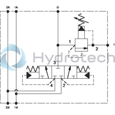
The Sun Hydraulics XRDCLNNA3 (Material Number: XRDCLNNA3) is a specialized valve assembly designed to provide a flushing circuit for hydrostatic transmissions. This product features a hot oil flushing circuit that effectively discharges oil from the low-pressure side of the loop, allowing the charge pump to replace hot, dirty oil with cool, filtered oil. This process helps in maintaining the efficiency and longevity of the transmission system by ensuring that both the pump and motor cases are flushed of contaminants. A unique aspect of this assembly is its ability to confirm or adjust the hot oil relief setting when the transmission is in neutral. The design includes two common ports marked as 1 and two as 2, which allows for easy integration by teeing off rather than plumbing directly into the loop. The XRDCLNNA3 model controls pressure with high-pressure reliefs located on either side; each relief manages pressure on its opposite port. When in neutral, charge pressure is regulated by the charge pump relief, and upon activation of the hot oil shuttle, some or all charge pump flow is redirected to the hot oil relief. To ensure optimal function, it is crucial that the charge pump relief is set higher than the hot oil relief to facilitate proper flow dynamics. The standard setting for this model's hot oil relief stands at 200 psi (14 bar) at a flow rate of 4 gpm (16 L/min). This assembly has a capacity of 10 gpm (40 L/min) and is designed for line mounting with four mounting holes. It's important to note that due to potential hydraulic motor leakage, employing a mechanical brake is recommended for securely locking any stopped live load.
The Sun Hydraulics XRDCLNNA3 (Material Number: XRDCLNNA3) is a specialized valve assembly designed to provide a flushing circuit for hydrostatic transmissions. This product features a hot oil flushing circuit that effectively discharges oil from the low-pressure side of the loop, allowing the charge pump to replace hot, dirty oil with cool, filtered oil. This process helps in maintaining the efficiency and longevity of the transmission system by ensuring that both the pump and motor cases are flushed of contaminants. A unique aspect of this assembly is its ability to confirm or adjust the hot oil relief setting when the transmission is in neutral. The design includes two common ports marked as 1 and two as 2, which allows for easy integration by teeing off rather than plumbing directly into the loop. The XRDCLNNA3 model controls pressure with high-pressure reliefs located on either side; each relief manages pressure on its opposite port. When in neutral, charge pressure is regulated by the charge pump relief, and upon activation of the hot oil shuttle, some or all charge pump flow is redirected to the hot oil relief. To ensure optimal function, it is crucial that the charge pump relief is set higher than the hot oil relief to facilitate proper flow dynamics. The standard setting for this model's hot oil relief stands at 200 psi (14 bar) at a flow rate of 4 gpm (16 L/min). This assembly has a capacity of 10 gpm (40 L/min) and is designed for line mounting with four mounting holes. It's important to note that due to potential hydraulic motor leakage, employing a mechanical brake is recommended for securely locking any stopped live load.
This valve assembly provides a flushing circuit for hydrostatic transmissions. The hot oil flushing circuit allows a discharge of oil from the low pressure side of the loop. The charge pump replaces the hot, dirty oil with cool, filtered oil. The hot oil discharge is often passed through the cases of the pump and the motor, flushing hot, dirty oil from them as well.
- A unique feature of the hot oil shuttle is that the setting of the hot oil relief can be confirmed or adjusted when the transmission is in neutral.
- The two ports marked 1 are common as are the two marked 2. Therefore the assembly can be teed off the loop rather than being plumbed into the loop.
- The two ports marked 1 are common as are the two marked 2. The high pressure relief that is physically on the same side as port 1 controls the pressure on port 2 and vice versa.
- When the transmission is in neutral the charge pressure is controlled by the charge pump relief. When the hot oil shuttle opens, some or all of the charge pump flow is redirected to the hot oil relief. The charge pump relief must be set higher than the hot oil relief to produce hot oil flow. The higher the differential pressure between the 2 reliefs, the higher the hot oil flow. The amount of hot oil flow is determined by the pressure vrs flow curves of the 2 reliefs and is difficult to quantify.
- The standard setting of the hot oil relief is 200 psi (14 bar) at a flow of 4 gpm (16 L/min).
- Hydraulic motors leak. Therefore a mechanical brake is recommended to positively lock any stopped live load.
| Capacity | 10 gpm40 L/min. |
| Body Type | Line mountLine mount |
| Mounting Hole Quantity | 44 |
Show FAQ
Additional Resources
- Protect Hydrostatic Transmission Circuits with Sun’s Delayed Shift Hot Oil Shuttle.
- Integrated Packages: Solutions That Grow Your Reputation
- Manufacturing Sun Cartridge Cavities
- Sun's Floating Style Screw-In Cartridge
- Sun Model Code Explanation; 999-901-334
- Custom Integrated Packages from Sun
- Fluid and Temperature Recommendations
Notes:
- Important: Carefully consider the maximum system pressure. The pressure rating of the manifold is dependent on the manifold material, with the port type/size a secondary consideration. Manifolds constructed of aluminum are not rated for pressures higher than 3000 psi (210 bar), regardless of the port type/size specified.