

SUN HYDRAULICS
PVDAWQV
$132.80 USD
Tags:
- SUN HYDRAULICS
- Material:PVDAWQV
- Model:PVDA-WQV
- Summary:Cartridge
Quantity in stock: 0
***Disclaimer: The following summary contains information gathered from various sources such as product descriptions, technical specifications and catalogs. While efforts have been made to provide accurate details, inaccuracies may occur. It is advised to verify all information by contacting Sun Hydraulics directly.***
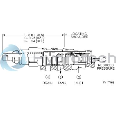
The Sun Hydraulics PVDAWQV (PVDAWQV) is an externally drained, pilot-operated pressure reducing/relieving valve designed to reduce a high primary pressure at the inlet port 2 to a constant reduced pressure at port 1. It features a full-flow relief function from port 1 to tank port 3, with the pilot section drained at port 4, making it insensitive to pressure at tank port 3 and allowing for remote control via pilot or two-way valves. The maximum pressure at port 3 should not exceed 3000 psi (210 bar), while the recommended maximum inlet pressure varies by adjustment range. Specifically, ranges D, E, N, and Q are tested with a maximum differential of 2000 psi (140 bar), ranges A, B, and H with 3000 psi (210 bar), and ranges C and W with an inlet pressure of up to 5000 psi (350 bar). The valve exhibits very low deadband transition between reducing and relieving modes and is characterized by exceptionally flat pressure-flow characteristics, stability, and low hysteresis. Pressure on drain port 4 directly adds to the valve setting in a 1:1 ratio and should not exceed 5000 psi (350 bar). While inherently not fast-acting due to its pilot-operated nature, it offers superior stability for applications requiring consistent pressure regulation. For dynamic response needs, direct-acting valves are recommended instead. The PVDAWQV model incorporates Sun's floating style construction to minimize internal part binding due to installation torque or machining variations. It has a cavity T-21A series capacity of 10 gpm (40 L/min) with factory-set pressures established under blocked control conditions. This model allows for reverse flow from reduced pressure port 1 to inlet port 2; however, if reverse free flow is required in the circuit, an additional check valve should be considered.
The Sun Hydraulics PVDAWQV (PVDAWQV) is an externally drained, pilot-operated pressure reducing/relieving valve designed to reduce a high primary pressure at the inlet port 2 to a constant reduced pressure at port 1. It features a full-flow relief function from port 1 to tank port 3, with the pilot section drained at port 4, making it insensitive to pressure at tank port 3 and allowing for remote control via pilot or two-way valves. The maximum pressure at port 3 should not exceed 3000 psi (210 bar), while the recommended maximum inlet pressure varies by adjustment range. Specifically, ranges D, E, N, and Q are tested with a maximum differential of 2000 psi (140 bar), ranges A, B, and H with 3000 psi (210 bar), and ranges C and W with an inlet pressure of up to 5000 psi (350 bar). The valve exhibits very low deadband transition between reducing and relieving modes and is characterized by exceptionally flat pressure-flow characteristics, stability, and low hysteresis. Pressure on drain port 4 directly adds to the valve setting in a 1:1 ratio and should not exceed 5000 psi (350 bar). While inherently not fast-acting due to its pilot-operated nature, it offers superior stability for applications requiring consistent pressure regulation. For dynamic response needs, direct-acting valves are recommended instead. The PVDAWQV model incorporates Sun's floating style construction to minimize internal part binding due to installation torque or machining variations. It has a cavity T-21A series capacity of 10 gpm (40 L/min) with factory-set pressures established under blocked control conditions. This model allows for reverse flow from reduced pressure port 1 to inlet port 2; however, if reverse free flow is required in the circuit, an additional check valve should be considered.
Externally drained, pilot-operated pressure reducing/relieving valves reduce a high primary pressure at the inlet (port 2) to a constant reduced pressure at port 1, with a full-flow relief function from port 1 to tank (port 3). Draining the pilot section at port 4 makes these valves insensitive to pressure at tank (port 3) and provides a means for remote control by pilot or 2-way valves.
- Maximum pressure at port 3 should be limited to 3000 psi (210 bar).
- Pilot operated valves exhibit very low dead-band transition between reducing and relieving modes.
- Recommended maximum inlet pressure is determined by the adjustment range. Ranges D, E, N, and Q are tested with a 2000 psi (140 bar) maximum differential between inlet and reduced pressure. Ranges A, B, and H are tested with a 3000 psi (210 bar) maximum differential between inlet and reduced pressure. Ranges C and W are tested with 5000 psi (350 bar) of inlet pressure.
- Pressure at port 4 should not exceed 5000 psi (350 bar).
- Pilot operated valves exhibit exceptionally flat pressure/flow characteristics, are very stable and have low hysteresis.
- Pressure on the drain (port 4) is directly additive to the valve setting at a 1:1 ratio and should not exceed 5000 psi (350 bar).
- Pilot operated reducing, reducing/relieving valves by nature are not fast acting valves. For superior dynamic response, consider direct acting valves.
- W and Y controls (where applicable) can be specified with or without a special setting. When no special setting is specified, the valve is adjustable throughout its full range using the W or Y control. When a special setting is specified, this setting represents the maximum setting of the valve.
- Full reverse flow from reduced pressure (port 1) to inlet (port 2) may cause the main spool to close. If reverse free flow is required in the circuit, consider adding a separate check valve to the circuit.
- By controlling the pressure at the drain (port 4), the effective setting of the valve can be increased over the nominal valve setting.
- Incorporates the Sun floating style construction to minimize the possibility of internal parts binding due to excessive installation torque and/or cavity/cartridge machining variations.
| Cavity | T-21A |
| Series | 1 |
| Capacity | 10 gpm40 L/min. |
| Factory Pressure Settings Established at | blocked control port (dead headed)blocked control port (dead headed) |
| Maximum Operating Pressure | 5000 psi350 bar |
| Control Pilot Flow | 7 - 10 in³/min.0,11 - 0,16 L/min. |
| Adjustment - Number of Clockwise Turns to Increase Setting | 55 |
| Valve Hex Size | 7/8 in.22,2 mm |
| Valve Installation Torque | 30 - 35 lbf ft41 - 47 Nm |
| Adjustment Screw Internal Hex Size | 5/32 in.4 mm |
| Locknut Hex Size | 9/16 in.15 mm |
| Locknut Torque | 80 - 90 lbf in.9 - 10 Nm |
| Model Weight | .30 lb0,15 kg |
| Seal kit - Cartridge | Viton: 990-021-006 |
Show FAQ
Additional Resources
- Sun Expands Corrosion-Resistant Solutions
- Series 4 PLUS Cartridges Offer Higher Flows with Lower Pressure Losses
- Sun Offers Zinc-Nickel Plating for Corrosion Resistance
- Sun Cartridges with EPDM Seals
- QuickDesign with SmartConnect Offers Drag-and-Drop Schematic Tool
- Reducing and Reducing/Relieving Valves
- Manufacturing Sun Cartridge Cavities
- Fluid and Temperature Recommendations
- Performance Data
- Sun's Floating Style Screw-In Cartridge
- Units of Measure, Settings, and Conversions
- Sun Model Code Explanation; 999-901-334
- Cavity Information (S-171) and Tooling
- Cartridges: Materials of Construction
Notes:
- Maximum pressure differentials for spring ranges: A and B are 3000 psi (210 bar) D and E are 2000 psi (140 bar) W is 5000 psi (350 bar) inlet pressure