

BOSCH REXROTH
R911173559
$985.51 USD
- BOSCH REXROTH
- Material:R911173559
- Model:S20-INC-2
Quantity in stock: 0
The Bosch Rexroth S20-INC-2 (R911173559) is a sophisticated incremental encoder interface module designed to be part of the S cabinet IO series. This module stands out with its modular and compact design, which allows for space-saving top hat rail mounting and offers a cost-effective solution for custom machine concepts. The robust mechanics of the S20-INC-2 ensure durability, while its forced ventilated axial fan contributes to reliable operation under various conditions. With fast reaction times and ease of handling, this module can be quickly installed both in control cabinets and in the field, streamlining the setup process. It supports open communication standards, ensuring seamless integration and maximum availability within diverse system environments. The innovative assembly concept enhances the flexibility of combining individual modules to meet specific application requirements. The S20-INC-2 is particularly adept at bussynchronous evaluation of positions detected by incremental encoder sensors within an S station setup. It features diagnostic and status indicators that facilitate monitoring and troubleshooting, contributing to reduced downtime and maintenance efforts. Additionally, this product's weight and type code extension are indicative of its design focus on simplicity and efficiency without compromising on functionality. As a component of Rexroth's ctrlX automation platform, the S20-INC-2 benefits from compatibility with a wide range of configurable options accessible through the ctrlX configurator. This ensures that users can tailor their IO systems to match their unique operational needs precisely. Its integration into EPLAN further simplifies electrical planning processes for engineers looking to incorporate this module into their systems. Designed with attention to detail, the Bosch Rexroth S20-INC-2 is an example of high-quality engineering aimed at enhancing machine automation with reliability and adaptability.
Cabinet I/O S20
The modular, compact device design of the I/O systems from Rexroth provides you with maximum flexibility for cost-effective implementation of your custom machine concepts. The I/O modules have a robust design and mechanics, Forced ventilated - Axial fan 230Vre easy to handle, have a fast reaction time and are quick to install – both in the control cabinet as well as in the field. Open communication standards allow you to perfectly integrate the I/O modules with maximum availability.
Unpacked Weight: 0.252 kg
This module is designed for use within an S20 station. It is used for bus-synchronous evaluation of the position of incremental encoder sensors.
| Innovative assembly and installation concept |
| Individually combinable modules |
| Space-saving I/O technology for top hat rail mounting |
| Compact, modular and simple |
| 2D CAD | Download 2D CAD |
| 3D CAD | Download 3D CAD |
| Type code extension | S20-INC-2 |
| Productgroup ID | 4,6 |
| ctrlX configurator | https://www.boschrexroth.com/ctrlx-configurator/ |
| Number of channels | 2 |
| EPLAN | https://ecad-configuration.boschrexroth.com/?rootpartnr=BOS.S20-INC-2**&downloads=true |
| Weight | 0.252 |
General data
|
Type |
S20-INC-2 | |
|
Color |
Gray | |
|
Weight 1) |
g |
205 |
|
Ambient temperature (operation) |
-25 °C ... +60 °C | |
|
Ambient temperature (storage/transport) |
-40 °C ... +85 °C | |
|
Permissible relative humidity (operation) |
5 % ... 95 %, no dewing | |
|
Permissible relative humidity (storage/transport) |
5 % ... 95 %, no dewing | |
|
Air pressure (operation) |
70 kPa ... 106 kPa (up to 3000 m above sea level) | |
|
Air pressure (storage/transport) |
70 kPa ... 106 kPa (up to 3000 m above sea level) | |
|
Protection type |
IP20 | |
|
Protection class |
III, IEC 61140, EN 61140, VDE 0140-1 | |
|
Installation position |
Any (no temperature derating) | |
| 1) | Including plug and bus base module |
Connection data
|
Type |
S20-INC-2 | |
|
Designation |
S20 connector | |
|
Connection type |
Push-in technology | |
|
Conductor cross-section solid/flexible/AWG |
0.2 mm² ... 1.5 mm² 0.2 mm² ... 1.5 mm² 24 ... 16 |
|
|
Stripping length |
mm |
8 |
Interface local bus
|
Type |
S20-INC-2 | |
|
Connection type |
Bus base module | |
|
Transmission speed |
MBit/s |
100 |
Power supply to logic
|
Type |
S20-INC-2 | |
|
Logic voltage UBus 1) |
V DC |
5 |
|
Typical current consumption from UBus |
mA |
100 |
|
Maximum current consumption from UBus |
mA |
120 |
|
Typical power consumption from UBus |
W |
0.5 |
|
Maximum power consumption from UBus |
W |
0.6 |
| 1) | Via bus base module |
Power supply to peripherals
|
Type |
S20-INC-2 | |
|
Feed to digital input modules UI |
V DC |
24 |
|
Maximum permitted voltage range 1) |
19.2 V DC ... 30 V DC | |
|
Typical current consumption from UI 2) |
mA |
50.5 |
|
Maximum current consumption from UI 3) |
A |
2.5 |
|
Typical power consumption from UI |
W |
1.2 |
|
Maximum power consumption from UI 4) |
W |
60 |
|
Overvoltage/reverse polarity protection supply voltage |
Electronic (35 V, 0.5 s) / parallel diode; with external security 5 A (only for commissioning) | |
|
Guarantee 5) |
A |
≤ 8 |
| 1) | Including all tolerances, including ripple |
| 2) | Internal current consumption; without wiring the terminal points |
| 3) | Depending on the encoder or sensor type used and the load on the digital output |
| 4) | Of which 1.6 W internal losses |
| 5) | Reverse polarity protection up to 5 A |
Incremental encoder inputs
|
Type |
S20-INC-2 | |
|
Number of inputs |
2 (A1, /A1, B1, /B1, Z1, /Z1; A2, /A2, B2, /B2, Z2, /Z2) | |
|
Encoder signals |
Symmetrical and asymmetrical encoders | |
|
Line length |
m |
30 |
Encoder types
|
Type |
S20-INC-2 | |
|
Symmetric incremental encoders |
||
|
Number |
≤2 (A, /A, B, /B, (Z, /Z)) | |
|
Signal connection type |
Push-in technology | |
|
Voltage level of the signals |
Difference signal (signal ‒ inverted signal) min. ±0.5 V, max. ±6 V | |
|
Input frequency |
Max. 300 kHz - |
|
|
Encoder supply voltage |
5 V DC | |
|
Common-mode voltage range signal ‒ ground |
-10 V ... 13.2 V | |
|
Asymmetric incremental encoders |
||
|
Number |
≤2 (A, B, (Z)) | |
|
Signal connection type |
Push-in technology | |
|
Voltage level of the signals ‒ low |
≤ 2.5 V | |
|
Voltage level of the signals ‒ high 1) |
≥ 3.5 V | |
|
Input frequency |
Max. 300 kHz - |
|
| 1) | Up to max. 27 V |
Encoder supply
|
Type |
S20-INC-2 | |
|
5 V encoder supply |
||
|
Number |
2 (UE1, UE2) | |
|
Nominal output voltage |
V DC |
5 |
|
Voltage range |
5 V DC ... 5.5 V DC | |
|
Current-carrying capacity |
mA |
≤ 2.5 |
|
Short-circuit protection |
Electronic | |
|
24 V encoder supply |
||
|
Number |
2 (US1, US2) | |
|
Nominal output voltage |
24 V DC | |
|
Voltage range |
19.2 V DC ... 30 V DC | |
|
Current-carrying capacity |
Typ. 500 mA | |
|
Short-circuit protection |
Electronic | |
Digital inputs
|
Type |
S20-INC-2 | |
|
Number of digital inputs |
10 (IN1 ... IN6, Ref1, Ref2, L1, L2) | |
|
Connection type |
Push-in technology | |
|
Connectivity technology |
1-wire technology (optional 2-, 3-wire) | |
|
Description of the input |
EN 61131-2 type 3 | |
|
Nominal input voltage |
V DC |
24 |
|
Nominal input current per channel |
mA |
2.5 |
|
Maximum sensor current per channel |
mA |
500 |
|
Input voltage range "0" signal |
-3 V DC ... 5 V DC | |
|
Input voltage range "1" signal |
11 V DC ... 30 V DC | |
|
Permissible cable length to sensor |
m |
30 |
|
Short-circuit protection |
Electronic, per channel | |
|
Overload protection |
Electronic, per channel | |
Digital outputs
|
Type |
S20-INC-2 | |||
|
Number of digital outputs |
2 (Out1, Out2) | |||
|
Connection type |
Push-in technology | |||
|
Connectivity technology |
1-wire technology | |||
|
Nominal output voltage |
24 V DC | |||
|
Output current per channel |
mA |
≤ 500 | ||
|
Nominal load |
Ohmic |
48 Ω; for nominal voltage |
W |
≤ 12 |
|
Lamps |
for nominal voltage |
W |
≤ 12 | |
|
Inductance |
1.2 H, 48 Ω; for nominal voltage |
VA |
≤ 12 | |
|
Short-circuit protection, overload protection of the outputs |
Yes | |||
Error messages to the higher-level control or computer system
|
Type |
S20-INC-2 | |
|
Error message |
Short-circuit/overload of digital outputs Error on the symmetrical incremental encoder |
|
Electrical isolation/insulation of the voltage ranges
|
Type |
S20-INC-2 | |
|
Test distance |
Test voltage | |
|
5 V supply (logic)/24 V supply (peripherals) |
500 V AC, 50 Hz, 1 min. | |
|
5 V supply (logic)/function earth |
500 V AC, 50 Hz, 1 min. | |
|
24 V supply (peripherals)/function earth |
500 V AC, 50 Hz, 1 min. | |
Mechanical tests
|
Type |
S20-INC-2 | |
|
Vibration resistance 1) |
g |
5 |
|
Shock 2) |
g |
30 |
|
Continuous shock 2) |
g |
10 |
| 1) | Acc. to EN 60068-2-6/IEC 60068-2-6 |
| 2) | Acc. to EN 60068-2-27/IEC 60068-2-27 |
Conformity
|
Type |
S20-INC-2 | ||
|
Conforms with |
|||
|
Testing of interference immunity acc. to EN 61000-6-2 |
Discharge of static electricity (ESD) |
Criterion B; 6 kV contact discharge; 8 kV air discharge acc. to EN 61000-4-2/IEC 61000-4-2 | |
|
Electro-magnetic fields |
Criterion A; field strength: 10 V/m acc. to EN 61000-4-3/IEC 61000-4-3 | ||
|
Fast transients (burst) |
Criterion B; 2 kV acc. to EN 61000-4-4/IEC 61000-4-4 | ||
|
Transient overvoltage (surge) |
Criterion B; supply lines DC: ±0.5 kV/±0.5 kV (symmetric/asymmetric) acc. to EN 61000-4-5/IEC 61000-4-5 | ||
|
Line-fed disturbances |
Criterion A; test voltage 10 V acc. to EN 61000-4-6/IEC 61000-4-6 | ||
|
Testing of disturbance transmission acc. to EN 61000-6-3 |
Radio disturbance characteristics |
Class B acc. to EN 55022 | |
|
Approvals |
|
The current approvals can be found at www.boschrexroth.com. |
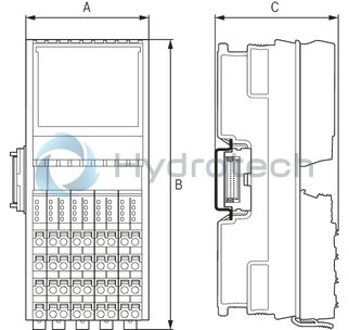
Dimensions
|
Type |
S20-INC-2 | |
|
A |
mm |
53.6 |
|
B |
mm |
126.1 |
|
C |
mm |
54 |
|
Note on dimensions |
The depth applies when using a support rail TH 35-7.5 (acc. to EN 60715). | |