

BOSCH REXROTH
R911173314
$1,867.77 USD
- BOSCH REXROTH
- Material:R911173314
- Model:R-IBIL24PSDI16-PAC
Quantity in stock: 0
The Bosch Rexroth R-IB IL 24 PSDI 16-PAC (R911173314) is an advanced input module designed to integrate seamlessly into an Inline station for industrial automation applications. This particular module is engineered to facilitate efficient and reliable signal processing within a control system. With its capability to manage up to 16 digital input signals, the R-IB IL 24 PSDI 16-PAC ensures high-density input collection, making it an ideal choice for systems where space is at a premium and multiple signal sources need to be accommodated. The unit's robust design allows it to operate effectively in diverse environmental conditions, ensuring consistent performance and durability. Its compatibility with the Inline station series streamlines installation and maintenance processes, as it can be easily snapped onto the bus coupler or other modules without the need for additional tools. Furthermore, this input module supports a wide range of power supply voltages and offers LED indicators for status monitoring of each input, enhancing diagnostics and troubleshooting procedures. Designed with precision by Bosch Rexroth, a leader in automation technology, the R-IB IL 24 PSDI 16-PAC module stands out for its reliability and efficiency in processing digital signals within complex automation systems. Whether used in manufacturing, processing, or other automated environments, this input module provides a high level of control and contributes significantly to the optimization of system operations.
Inline connector
The modular, compact equipment configuration of the I/O systems from Rexroth offers you maximum flexibility for the cost-effective implementation of your individual machine concepts. The I/O modules have robust design and mechanics, are easy to use, have a quick reaction time and are quick to install – both in the control cabinet and in the field. Open communication standards allow you perfect integration of the I/O modules with maximum availability.
Unpacked Weight: 0.398 kg
The R-IB IL 24 PSDI 16-PAC module is an input module that is assigned for use within an Inline station.
| 3D CAD | Download 3D CAD |
| Manual | Download Manual |
| Air pressure (operation) | 80-108 kPa (up to 2,000 m above sea level) |
| Width | 48.8 |
| Productgroup ID | 4,6 |
| Height | 140.5 |
| International protection code | IP20 |
| Permissible air humidity (storage) | 75 |
| Permissible air humidity (transport) | 75 |
| Number of channels | 16 |
| Connection type | Zugfederanschluss |
| Depth | 71.5 |
| Weight | 0.398 |
| Ambient temperature (during operation) | -25-55 |
| Ambient temperature (storage and transport) | -25-70 |
| Conductor cross-section | Rigid: 0.2-1.5 mm²,Flexible: 0.2-1.5 mm²,AWG: 24 ... 16 |
General data
|
Type |
R-IB IL 24 PSDI 16-PAC | |
|
Weight 1) |
g |
225 |
|
Operating mode |
PROFIsafe process data mode with 4 words and 1 word PCP (internal use) | |
|
Ambient temperature (operation) |
-25 °C ... +55 °C | |
|
Ambient temperature (storage/transport) |
-25 °C ... +70 °C | |
|
Permissible relative humidity (operation) |
75% on average, 85% occasionally (no condensation) | |
|
Permissible relative humidity (storage/transport) |
75% on average, 85% occasionally (no condensation) | |
|
Air pressure (operation) |
80 kPa … 108 kPa (up to 2000 m above sea level) | |
|
Air pressure (storage/transport) |
66 kPa … 108 kPa (up to 3500 m above sea level) | |
|
Protection type |
IP20 | |
|
Protection class |
III | |
|
Clearances and creepage distances |
Acc. to IEC 60664-1 | |
|
Housing material |
Plastic PBT, self-extinguishing (V0) | |
| 1) | Including plug |
Interface local bus
|
Type |
R-IB IL 24 PSDI 16-PAC | |
|
Transmission speed |
kBaud MBaud |
500 2 |
Safety characteristics
|
Type |
R-IB IL 24 PSDI 16-PAC | |
|
Acc. to IEC 61508/EN 61508 |
||
|
Achievable SIL 1) |
SIL 2 (single-channel) SIL 3 (two-channel) - |
|
|
Probability of dangerous failure by demand through the safety function (PFD) |
SIL 2: Maximum 1 % of 10-2 (corresponds to 1 * 10-4) SIL 3: Maximum 1 % of 10-3 (corresponds to 1 * 10-5) |
|
|
Probability of dangerous failure per hour for the whole module (PFH) 2) |
SIL 2: Maximum 1 % of 10-6 (corresponds to 1 * 10-8) SIL 3: Maximum 1 % of 10-7 (corresponds to 1 * 10-9) - |
|
|
Hardware error tolerance (HFT) of the module |
1 | |
|
Permissible operating time |
Years |
20 |
|
Acc. to EN 62061 |
||
|
Achievable SIL Claim Limit 1) |
SIL CL 2 = SIL 2 (single-channel) SIL CL 3 = SIL 3 (two-channel) - |
|
|
Safe Failure Fraction (SFF) |
% |
99 |
|
Probability of dangerous failure per hour for the whole module (PFH) 1) |
SIL 2: Maximum 1 % of 10-6 (corresponds to 1 * 10-8) SIL 3: Maximum 1 % of 10-7 (corresponds to 1 * 10-9) - |
|
|
Hardware error tolerance (HFT) of the module |
1 | |
|
Permissible operating time |
Years |
20 |
|
Acc. to EN ISO 13849-1 |
||
|
Achievable Performance Level 1) |
PL e (two-channel) PL d (single-channel) - |
|
|
Degree of diagnostic cover (DC) |
% |
99 |
|
Mean time to a dangerous failure (MTTFd) |
For single-channel occupancy: 76 years For two-channel occupancy: 100 years |
|
| 1) | Depending on the parameterization and circuit |
| 2) | Depending on the parameterization |
Supply voltage UL
|
Type |
R-IB IL 24 PSDI 16-PAC | |
|
Maximum current consumption |
mA |
≤ 190 |
Supply voltage UM
|
Type |
R-IB IL 24 PSDI 16-PAC | |
|
Nominal voltage 1) |
V DC |
24 |
|
Tolerance |
-15 %/+20 % including an overall alternating current component with peak value 5 % | |
|
Ripple |
Vpp |
3.6 |
|
Permissible voltage range 2) |
19.2 V DC ... 30 V DC | |
|
Typical current consumption 3) |
mA |
10 |
|
Permitted interruption time 4) |
ms |
10 |
|
Overvoltage protection |
Protection elements of the bus coupler or the feed module | |
|
Reverse polarity protection |
Protection elements of the bus coupler or the feed module | |
|
Undervoltage detection |
V |
≈ 17 |
|
Diagnosis displays |
LED (green) UM | |
|
External protection 5) |
A |
≤ 8 |
| 1) | Acc. to EN 61131-2, EN 60204 |
| 2) | Including ripple |
| 3) |
Plus current consumption of inputs when supplied through the clock outputs Plus current consumption of connected initiators when supplied through the clock outputs |
| 4) | Output voltage of the clock outputs can break down |
| 5) | Slow time-lag |
Safe digital inputs
|
Type |
R-IB IL 24 PSDI 16-PAC | ||
|
Number of digital inputs |
8/16 (two-channel/single-channel) | ||
|
Dimensioning of inputs |
Acc. to EN 61131-2 type 3 | ||
|
Supply |
Via clock outputs UT1 and UT2 or external supply | ||
|
Typical input current |
mA |
2.7 | |
|
Maximum permissible current "0" signal |
mA |
1.5 | |
|
Minimum permissible current "1" signal |
mA |
2 | |
|
Permissible input voltage range |
-3 V ... +30 V | ||
|
Input voltage range "0" signal |
-3 V … +5 V | ||
|
Input voltage range "1" signal |
+11 V … +30 V | ||
|
Maximum switching frequency |
Hz |
10 | |
|
Filter time |
tFilters |
Configurable | |
|
Minimum 1) |
ms |
3 | |
|
Processing time for the input |
tIN = tFilters + tFW | ||
|
Simultaneity |
% |
100 | |
|
Evaluation of the symmetry |
Yes, configurable, accuracy ±25 % | ||
|
Derating |
No | ||
|
Permissible cable length 2) |
m |
500 | |
|
Status display |
One green LED per input | ||
| 1) | Accuracy +0 ms, -0.5 ms |
| 2) | From clock output to secure input (total from forward and return path) |
Clock outputs
|
Type |
R-IB IL 24 PSDI 16-PAC | |
|
Number of clock outputs |
2 | |
|
Supply |
From UM | |
|
Maximum switching current 1) |
A |
≤ 0.2 |
|
Saturation voltage |
UM ‒ 1 V | |
|
Simultaneity |
% |
100 |
|
Derating |
No | |
|
Permissible cable length 2) |
m |
≤ 500 |
|
Status indicators |
None | |
|
Diagnosis displays |
One red LED for each (UT1, UT2) | |
| 1) | Short-circuit and overload proof |
| 2) | Total of connected up lines for each clock output must not be exceeded |
Electrical isolation/insulation of the voltage ranges
|
Type |
R-IB IL 24 PSDI 16-PAC | |
|
Common potentials |
||
|
For the potential separation of the logic layer from the peripheral area, it is necessary to use separate power supplies when supplying the station's bus coupler and the safety module described here. A connection to the supply devices in the 24 V range is not allowed! (See also application description.) |
||
|
Separate potentials in the system of bus coupler/feed module and safety module |
||
|
Test distance |
Test voltage | |
|
5 V supply incoming remote bus/7.5 V supply (bus logic) |
500 V AC, 50 Hz, 1 min. | |
|
5 V supply to further remote bus/7.5 V supply (bus logic) |
500 V AC, 50 Hz, 1 min. | |
|
7.5 V power supply (bus logic)/24 V power supply UM, FE |
500 V AC, 50 Hz, 1 min. | |
Mechanical tests
|
Type |
R-IB IL 24 PSDI 16-PAC | |
|
Vibration resistance 1) |
Operation: 2 g; criterion A | |
|
Shock 2) |
15 g, 11 ms; criterion A | |
| 1) | Acc. to IEC 60068-2-6 |
| 2) | Acc. to IEC 60068-2-27 |
Power dissipation
|
Type |
R-IB IL 24 PSDI 16-PAC | ||
|
At UM = 24 V |
No input set 1) |
mW |
1200 |
|
16 inputs set 2) |
mW |
2600 | |
| 1) | Without load on the clock outputs UT1 and UT2 |
| 2) | Load on the clock outputs UT1 and UT2 each 100 mA |
Conformity
|
Type |
R-IB IL 24 PSDI 16-PAC | ||
|
Conforms with |
|||
|
Testing of interference immunity acc. to EN 61000-6-2 |
Discharge of static electricity (ESD) |
Criterion B; 6 kV contact discharge; 8 kV air discharge acc. to EN 61000-4-2/IEC 61000-4-2 | |
|
Electro-magnetic fields |
Criterion A; field strength: 10 V/m acc. to EN 61000-4-3/IEC 61000-4-3 | ||
|
Fast transients (burst) |
Criterion B; test voltage 2 kV acc. to EN 61000-4-4/IEC 61000-4-4 | ||
|
Transient overvoltage (surge) |
Testing severity 2, criterion B;supply lines DC: ±0.5 kV/±0.5 kV (symmetric/asymmetric); signal lines: ±1 kV/±2 kV (symmetric/asymmetric) acc. to EN 61000-4-5/IEC 61000-4-5 | ||
|
Line-fed disturbances (ODS) |
Criterion A; test voltage 10 V acc. to EN 61000-4-6/IEC 61000-4-6 | ||
|
Testing of disturbance transmission acc. to EN 61000-6-4 |
Testing of line-fed disturbance transmission |
Class A, industrial area acc. to EN 55011 | |
|
Approvals |
|
The current approvals can be found at www.boschrexroth.com. |
|
Approvals |
|
The current approvals can be found at www.boschrexroth.com. |
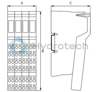
Dimensions
|
Type |
R-IB IL 24 PSDI 16-PAC | |
|
A |
mm |
48.8 |
|
B |
mm |
140.5 |
|
C |
mm |
71.5 |
|
Note on dimensions |
The depth applies when using a support rail TH 35-7.5 (acc. to EN 60715). | |