

BOSCH REXROTH
R911172848
$1,660.85 USD
- BOSCH REXROTH
- Material:R911172848
- Model:R-IBIL24PSDOR4-PAC
Quantity in stock: 0
Inline connector / COMBICON connector
The modular, compact equipment configuration of the I/O systems from Rexroth offers you maximum flexibility for the cost-effective implementation of your individual machine concepts. The I/O modules have robust design and mechanics, are easy to use, have a quick reaction time and are quick to install – both in the control cabinet and in the field. Open communication standards allow you perfect integration of the I/O modules with maximum availability.
Unpacked Weight: 0.451 kg
| Data Sheet | Download Data Sheet |
| 3D CAD | Download 3D CAD |
| Manual | Download Manual |
| Air pressure (operation) | 80-108 kPa (up to 2,000 m above sea level) |
| Air pressure (storage / transport) | 70-106 kPa (up to 3,000 m above sea level) |
| Width | 73.2 |
| Productgroup ID | 4,6 |
| Height | 120 |
| International protection code | IP20 |
| Permissible air humidity (storage) | 75 |
| Permissible air humidity (transport) | 75 |
| Connection type | Zugfederanschluss |
| Depth | 71.5 |
| Weight | 0.451 |
| Ambient temperature (during operation) | -25-55 |
| Ambient temperature (storage and transport) | -25-70 |
| Conductor cross-section | Rigid: 0.2-1.5 mm²,Flexible: 0.2-1.5 mm²,AWG: 24 ... 16,Rigid: 0.2-2.5 mm²,Flexible: 0.2-2.5 mm²,AWG: 24 ... 12 |
General data
|
Type |
R-IB IL 24 PSDOR 4-PAC | |
|
Weight 1) |
g |
310 |
|
Operating mode |
PROFIsafe process data mode with 4 words and 1 word PCP (internal use) | |
|
Ambient temperature (operation) |
-25 °C ... +55 °C | |
|
Ambient temperature (storage/transport) |
-25 °C ... +70 °C | |
|
Permissible relative humidity (operation) |
75% on average, 85% occasionally (no condensation) | |
|
Permissible relative humidity (storage/transport) |
75% (no dewing) | |
|
Air pressure (operation) |
80 kPa … 108 kPa (up to 2000 m above sea level) | |
|
Air pressure (storage/transport) |
66 kPa … 108 kPa (up to 3500 m above sea level) | |
|
Protection type |
IP20 | |
|
Protection class |
II, IEC 61140, EN 61140, VDE 0140-1 | |
|
Clearances and creepage distances |
Acc. to IEC 60664-1 | |
|
Housing material |
Plastic PBT, self-extinguishing (V0) | |
|
Supported stop category |
0; 1 in error-free state acc. to EN 60204 | |
| 1) | Including plug |
Connection data
|
Type |
R-IB IL 24 PSDOR 4-PAC | |
|
Inline connection plug |
||
|
Connection type |
Tension spring modules | |
|
Conductor cross-section solid/flexible/AWG |
0.2 mm² ... 1.5 mm² 0.2 mm² ... 1.5 mm² 24 ... 16 |
|
|
Permissible current |
A |
≤ 4 |
|
Guarantee |
A |
≤ 4 |
|
COMBICON plug |
||
|
Connection type |
Tension spring modules | |
|
Conductor cross-section solid/flexible/AWG |
0.2 mm² ... 2.5 mm² 0.2 mm² ... 2.5 mm² 24 ... 12 |
|
|
Conductor cross-section with ferrule without/with plastic sleeve |
0.25 mm² ... 2.5 mm² 24 ... 12 - |
|
Interface local bus
|
Type |
R-IB IL 24 PSDOR 4-PAC | |
|
Transmission speed |
kBaud MBaud |
500 2 |
Safety characteristics
|
Type |
R-IB IL 24 PSDOR 4-PAC | ||
|
Acc. to IEC 61508/EN 61508 |
|||
|
Achievable SIL 1) |
SIL 2 (single-channel) SIL 3 (two-channel) - |
||
|
Probability of dangerous failure by demand through the safety function (PFD) |
SIL 2: Maximum 1 % of 10-2 (corresponds to 1 * 10-4) SIL 3: Maximum 1 % of 10-3 (corresponds to 1 * 10-5) |
||
|
Probability of dangerous failure per hour for the whole module (PFH) 2) |
SIL CL 2: Maximum 1 % of 10-6 (corresponds to 1 * 10-8) SIL CL 3: Maximum 1 % of 10-7 (corresponds to 1 * 10-9) - |
||
|
Hardware error tolerance (HFT) of the module |
For single-channel occupancy |
0 | |
|
For two-channel occupancy |
1 | ||
|
Permissible operating time |
Years |
20 | |
|
Acc. to EN 62061 |
|||
|
Achievable SIL Claim Limit 1) |
SIL CL 2 = SIL 2 (single-channel) SIL CL 3 = SIL 3 (two-channel) - |
||
|
Safe Failure Fraction (SFF) |
% |
99 | |
|
Probability of dangerous failure per hour for the whole module (PFH) 2) |
SIL CL 2: Maximum 1 % of 10-6 (corresponds to 1 * 10-8) SIL CL 3: Maximum 1 % of 10-7 (corresponds to 1 * 10-9) - |
||
|
Hardware error tolerance (HFT) of the module |
For single-channel occupancy |
0 | |
|
For two-channel occupancy |
1 | ||
|
Permissible operating time |
Years |
20 | |
|
Acc. to EN ISO 13849-1 |
|||
|
Achievable Performance Level 1) |
PL e (two-channel) PL d (single-channel) - |
||
|
Degree of diagnostic cover (DC) |
% |
99 | |
|
Mean time to a dangerous failure (MTTFd) 2) |
For single-channel occupancy: 100 years For two-channel occupancy: 100 years |
||
| 1) | Depending on the parameterization and circuit |
| 2) | Depending on the load, switching frequency, parameterization, and circuit |
Supply voltage UL
|
Type |
R-IB IL 24 PSDOR 4-PAC | |
|
Maximum current consumption |
mA |
≤ 360 |
|
Diagnosis displays |
Indirectly via green LED D | |
Supply voltage UM
|
Type |
R-IB IL 24 PSDOR 4-PAC | |
|
Nominal voltage 1) |
V DC |
24 |
|
Tolerance |
-15 %/+20 % including an overall alternating current component with peak value 5 % | |
|
Ripple |
Vpp |
3.6 |
|
Permissible voltage range 2) |
19.2 V DC ... 30 V DC | |
|
Typical current consumption |
mA |
30 |
|
Permitted interruption time 3) |
ms |
10 |
|
Overvoltage protection |
Protective elements of the bus coupler or the feed module; in addition, internal overvoltage protection (suppressor diode between UM and GND) | |
|
Reverse polarity protection |
Protection elements of the bus coupler or the feed module | |
|
Undervoltage detection |
No | |
|
Diagnosis displays |
None | |
|
External protection 4) |
A |
≤ 8 |
| 1) | Acc. to EN 61131-2, EN 60204 |
| 2) | Including ripple |
| 3) | Within this period of time, the output voltage for the secure outputs breaks down, since the outputs are not buffered internally. The dip in the supply voltage can lead to the safety relay being switched off and to a diagnostic message |
| 4) | Slow time-lag |
Safe digital relay outputs
|
Type |
R-IB IL 24 PSDOR 4-PAC | ||
|
Number of safety relays |
4 | ||
|
Number of floating contacts |
8 | ||
|
Power supply to the coils |
Off UL | ||
|
Supply |
From the clock outputs UT1 and UT2 | ||
|
Permissible switching voltage range |
Inline connection plug |
5 V AC/DC ... 30 V AC/DC | |
|
COMBICON plug |
5 V AC/DC ... 250 V AC/DC | ||
|
Maximum output current per contact 1) |
Inline connection plug |
A |
4 |
|
COMBICON plug |
A |
6 | |
|
Mechanical service life |
> 10*106 switching cycles | ||
|
N/O contact typical bouncing time |
ms |
2 | |
|
Maximum switching frequency |
1 per second (depending on the SIL requirement) - - |
||
|
Proof test interval |
m |
6 | |
|
External protection |
Nominal current ≤6 A, melting integral <100 A2s - - - |
||
|
Simultaneity 2) |
% |
100 | |
|
Switch-off delay for shutdown 3) |
150 ms ... 630 s | ||
|
Status display |
One green LED per relay output (two-color LED green/red) | ||
|
Diagnosis displays |
One red LED per relay output (two-color LED green/red) | ||
| 1) | Observe derating |
| 2) | Observe maximum current load |
| 3) | After stop category 1; precision ±5 % of parameterized value |
Clock outputs
|
Type |
R-IB IL 24 PSDOR 4-PAC | |
|
Number of clock outputs |
2 | |
|
Supply |
From UM | |
|
Maximum switching current 1) |
mA |
≈ 15 |
|
Simultaneity |
% |
100 |
|
Derating |
No | |
|
Status indicators |
None | |
|
Diagnosis displays |
None | |
| 1) | Short-circuit and overload proof |
Contact data of the safety relay used
|
Type |
R-IB IL 24 PSDOR 4-PAC | ||
|
Contact material |
AgCUNi + 0.2-0.45 µm Au | ||
|
Contact type |
Single contact | ||
|
Nominal switching power |
250 V AC 6 A AC1 1500 VA | ||
|
Electrical service life |
Around 100,000 AC1 (360S/h) | ||
|
Switch-on current 1) |
A |
≤ 30 | |
|
Switching voltage range |
5 V AC/DC ... 250 V AC/DC | ||
|
Switching current range |
5 mA ... 6 A | ||
|
Switching capacity range |
60 mW ... 1,500 W | ||
|
Contact transfer resistance |
mΩ |
≤ 100 | |
|
Protection against short circuit |
1000 A SCPD (6 A gG fuse) | ||
|
Maximum switching capacity acc. to EN 60947-4-1/EN 60947-5-1 |
AC 1 |
250 V/6 A | |
|
AC 15 |
230 V/3 A | ||
|
DC 1 |
24 V/6 A | ||
|
DC 13 |
24 V/5 A/0.1 Hz | ||
|
Maximum shut-off capacity |
24 V DC |
W |
144 |
|
48 V DC |
W |
96 | |
|
110 V DC |
W |
66 | |
|
250 V DC |
W |
63 | |
|
250 V AC |
VA |
1500 | |
|
Maximum shut-off capacity |
24 V DC |
W |
35 |
|
48 V DC |
W |
35 | |
|
110 V DC |
W |
35 | |
|
250 V DC |
W |
35 | |
| 1) | For 20 ms |
Mechanical tests
|
Type |
R-IB IL 24 PSDOR 4-PAC | |
|
Vibration resistance 1) |
Operation: 2 g; criterion A | |
|
Shock 2) |
15 g, 11 ms; criterion A | |
| 1) | Acc. to IEC 60068-2-6 |
| 2) | Acc. to IEC 60068-2-27 |
Conformity
|
Type |
R-IB IL 24 PSDOR 4-PAC | ||
|
Conforms with |
|||
|
Testing of interference immunity acc. to EN 61000-6-2 |
Discharge of static electricity (ESD) |
Criterion B; 6 kV contact discharge; 8 kV air discharge acc. to EN 61000-4-2/IEC 61000-4-2 | |
|
Electro-magnetic fields |
Criterion A; field strength: 10 V/m acc. to EN 61000-4-3/IEC 61000-4-3 | ||
|
Fast transients (burst) |
Criterion B; test voltage 2 kV acc. to EN 61000-4-4/IEC 61000-4-4 | ||
|
Transient overvoltage (surge) |
Testing severity 2, criterion B;supply lines DC: ±0.5 kV/±0.5 kV (symmetric/asymmetric); signal lines: ±1 kV/±2 kV (symmetric/asymmetric) acc. to EN 61000-4-5/IEC 61000-4-5 | ||
|
Line-fed disturbances |
Criterion A; test voltage 10 V acc. to EN 61000-4-6/IEC 61000-4-6 | ||
|
Testing of disturbance transmission acc. to EN 61000-6-4 |
Testing of line-fed disturbance transmission |
Class A, industrial area acc. to EN 55011 | |
Message inputs
|
Type |
R-IB IL 24 PSDOR 4-PAC | |
|
Number of message inputs |
2 | |
|
Supply |
From the clock outputs UT1 and UT2 | |
|
Typical input current |
mA |
5.5 |
|
Simultaneity 1) |
% |
100 |
|
Derating |
No | |
|
Status indicators |
One green LED per message input | |
|
Diagnosis displays |
None | |
| 1) | Observe maximum current load |
|
Approvals |
|
The current approvals can be found at www.boschrexroth.com. |
Electrical isolation/insulation of the voltage ranges
|
Type |
R-IB IL 24 PSDOR 4-PAC | |
|
Common potentials |
||
|
For the potential separation of the logic layer from the peripheral area, it is necessary to use separate power supplies when supplying the station's bus coupler and the safety module described here. A connection to the supply devices in the 24 V range is not allowed! (See also application description.) |
||
|
Separate potentials in the system of bus coupler/feed module and safety module |
||
|
Test distance |
Test voltage | |
|
5 V supply incoming remote bus/7.5 V supply (bus logic) |
500 V AC, 50 Hz, 1 min. | |
|
5 V supply to further remote bus/7.5 V supply (bus logic) |
500 V AC, 50 Hz, 1 min. | |
|
7.5 V supply (bus logic)/24 V supply UM, 24 V supply US, GND, clock outputs, relay outputs, FE |
500 V AC, 50 Hz, 1 min. | |
|
24 V supply UM, 24 V supply US, GND, clock outputs/7.5 V supply (bus logic), relay outputs |
500 V AC, 50 Hz, 1 min. | |
|
Relay outputs COMBICON X3/relay outputs COMBICON X4, relay outputs Inline plug, 7.5 V supply (bus logic), 24 V supply UM, 24 V supply US, GND, clock outputs, FE |
2500 V AC, 50 Hz, 1 min. | |
|
Relay outputs COMBICON X4/relay outputs COMBICON X3, relay outputs Inline plug, 7.5 V supply (bus logic), 24 V supply UM, 24 V supply US, GND, clock outputs, FE |
2500 V AC, 50 Hz, 1 min. | |
|
Approvals |
|
The current approvals can be found at www.boschrexroth.com. |
|
Approvals |
|
The current approvals can be found at www.boschrexroth.com. |
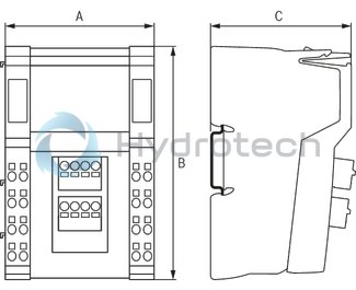
Dimensions
|
Type |
R-IB IL 24 PSDOR 4-PAC | |
|
A |
mm |
73.2 |
|
B |
mm |
120 |
|
C |
mm |
71.5 |
|
Note on dimensions |
The depth applies when using a support rail TH 35-7.5 (acc. to EN 60715). | |