

BOSCH REXROTH
R911171971
$2,018.43 USD
- BOSCH REXROTH
- Material:R911171971
- Model:R-IBIL24IOL4DI12-PAC
Quantity in stock: 0
The Bosch Rexroth R-IB IL 24 IOL 4 DI 12-PAC (R911171971) is a high-performance I/O terminal designed for seamless integration within an Inline station. This terminal is specifically engineered to facilitate the operation of IO-Link capable sensors and actuators, as well as to acquire digital signals with precision and ease. The IO-Link technology embedded in this unit represents the industry standard for enabling comprehensive communication from the control system right down to field level devices. The R-IB IL 24 IOL 4 DI 12-PAC leverages the familiar signaling technology of a binary 24V interface, utilizing pulse modulation to transmit data effectively while maintaining simultaneous service data exchange. This ensures that process data are consistently relayed even during parallel transfers. The point-to-point connectivity between the IO-Link port and connected sensors or actuators underscores the unit's streamlined communication capabilities. Compatibility is a key feature of this terminal, which supports all IO-Link capable devices across various networks including INTERBUS, PROFIBUS, and PROFINET systems. Its backward compatibility with standard sensors and actuators ensures that it can be integrated into existing setups without requiring extensive modifications. The Bosch Rexroth R-IB IL 24 IOL 4 DI 12-PAC is designed to be utilized across diverse industries, offering versatility and reliability for a wide range of applications that demand precise sensor/actuator operation and digital signal acquisition.
The modular, compact equipment configuration of the I/O systems from Rexroth offers you maximum flexibility for the cost-effective implementation of your individual machine concepts. The I/O modules have robust design and mechanics, are easy to use, have a quick reaction time and are quick to install – both in the control cabinet and in the field. Open communication standards allow you perfect integration of the I/O modules with maximum availability.
Unpacked Weight: 0.235 kg
This terminal is designed for use within an Inline station. It enables the operation of IO-Link-capable sensors and actuators (devices). It is also used to acquire digital signals. IO-Link is the standard for integrated communication from the controller to the lowest field level. In IO-Link communication, the process data are forwarded in the event of parallel service data transfer. IO-Link is a point-to-point connection between an IO-Link port and the sensor or actuator. IO-Link technology uses the well-known signaling technology of a binary 0 V and 24 V interface in order to transfer data with the aid of pulse modulation. The backward compatibility with standard sensors/actuators is met by IO-Link. This unit can be used to operate all IO-Link capable devices on INTERBUS, on PROFIBUS, and on a PROFINET system - and can be used industry-wide.
| Data Sheet | Download Data Sheet |
| Manual | Download Manual |
| Air pressure (storage / transport) | 70-106 kPa (up to 3,000 m above sea level) |
| Width | 48.8 |
| Productgroup ID | 4,6 |
| Height | 140.5 |
| Depth | 71.5 |
| Weight | 0.235 |
General data
|
Type |
R-IB IL 24 IOL 4 DI 12-PAC | |
|
Weight 1) |
g |
200 |
|
Operating mode |
Process data operation with 6 words, PCP with 1 word | |
|
Ambient temperature (operation) |
-25 °C ... +55 °C | |
|
Ambient temperature (storage/transport) |
-25 °C ... +85 °C | |
|
Permissible relative humidity (operation) |
10 % ... 95 % acc. to DIN EN 61131-2 | |
|
Permissible relative humidity (storage/transport) |
10 % ... 95 % acc. to DIN EN 61131-2 | |
|
Air pressure (operation) |
70 kPa ... 106 kPa (up to 3000 m above sea level) | |
|
Air pressure (storage/transport) |
70 kPa ... 106 kPa (up to 3000 m above sea level) | |
|
Protection type |
IP20 | |
|
Protection class |
III, IEC 61140, EN 61140, VDE 0140-1 | |
| 1) | Including plug |
Connection data
|
Type |
R-IB IL 24 IOL 4 DI 12-PAC | |
|
Designation |
Inline connection plug | |
|
Connection type |
Spring-cage connection | |
|
Conductor cross-section solid/flexible/AWG |
0.2 mm² ... 1.5 mm² 0.2 mm² ... 1.5 mm² 24 ... 16 |
|
Interface local bus
|
Type |
R-IB IL 24 IOL 4 DI 12-PAC | |
|
Connection type |
Inline data jumper | |
|
Transmission speed |
kBit/s |
500 |
IO-Link port power supply
|
Type |
R-IB IL 24 IOL 4 DI 12-PAC | ||
|
Peripherals power supply voltage US |
V |
≥ 1 | |
|
Rated current |
Per IO-Link port |
mA |
≤ 200 |
|
Per device |
mA |
≤ 800 | |
|
Permissible cable length to sensor |
m |
20 | |
Inline potentials/performance balance
|
Type |
R-IB IL 24 IOL 4 DI 12-PAC | ||
|
Segment supply voltage US 1) |
V DC |
24 | |
|
Current consumption from US |
With load and port supply |
A |
≤ 2 |
|
No load |
mA |
≤ 52 | |
|
Logic voltage UL 2) |
V DC |
7.5 | |
|
Current consumption from UL |
mA |
≤ 100 | |
| 1) | Rated value |
| 2) | Via potential jumpers |
Digital inputs in the SIO mode
|
Type |
R-IB IL 24 IOL 4 DI 12-PAC | ||
|
Number of digital inputs |
≤ 4 | ||
|
Connection type |
Inline connection plug | ||
|
Input voltage |
V DC |
24 | |
|
Input voltage range |
0 V DC ... 30 V DC | ||
|
Nominal input current at 24 V DC |
mA |
5.5 | |
|
Current profile |
Linear in the range |
0 V ... 10 V | |
|
Constant in the range |
7 V ... 30 V | ||
|
Maximum voltage of the low level |
V |
5 | |
|
Minimum voltage of the high level |
V |
15 | |
|
Input voltage range "0" signal |
Delay time upon signal change from 0 to 1 |
ms |
3 |
|
Delay time upon signal change from 1 to 0 |
ms |
3 | |
|
Permissible cable length to sensor |
m |
20 | |
Digital outputs in the SIO mode
|
Type |
R-IB IL 24 IOL 4 DI 12-PAC | |
|
Number of digital outputs |
≤ 4 | |
|
Nominal output voltage US 1) |
V |
3 |
|
Nominal current per channel |
≤200 mA (INenn) | |
|
Total power consumption |
mA |
≤ 800 |
|
Limited inductive cut-off voltage |
V |
≈ - 1 |
|
Short-circuit protection |
Integrated per channel | |
|
Switching frequency |
Hz |
≤ 300 |
| 1) | UOUT at ICQ ≤ 300 mA |
Digital inputs
|
Type |
R-IB IL 24 IOL 4 DI 12-PAC | ||
|
Number of digital inputs |
12 | ||
|
Description of the input |
Acc. to IEC 61131-2, type 1 | ||
|
Connection type |
Inline connection plug | ||
|
Connectivity technology |
2-, 3-wire technology | ||
|
Nominal input voltage |
V DC |
24 | |
|
Input voltage range |
0 V DC ... 30 V DC | ||
|
Nominal input current |
mA |
2.2 | |
|
Current profile |
Linear in the range |
0 V ... 10 V | |
|
Constant in the range |
10 V ... 30 V | ||
|
Input voltage range "0" signal |
< 5 V | ||
|
Input voltage range "1" signal |
> 11 V | ||
|
Typical delay time upon signal change from 0 to 1 |
ms |
3 | |
|
Typical delay time upon signal change from 1 to 0 |
ms |
3 | |
|
Permissible cable length to sensor |
m |
20 | |
Programming data
|
Type |
R-IB IL 24 IOL 4 DI 12-PAC | |
|
ID code (hex) |
DF | |
|
ID code (dec) |
223 | |
|
Length code (hex) |
06 | |
|
Length code (dec) |
6 | |
|
Process data channel |
bits |
96 |
|
Input address room |
byte |
12 |
|
Output address room |
byte |
12 |
|
Parameter channel (PCP) |
byte |
2 |
|
Register length (bus) |
bits |
112 |
Fieldbus data telegram
|
Type |
R-IB IL 24 IOL 4 DI 12-PAC | |
|
Need for parameter data |
byte |
35 |
|
Need for configuration data |
byte |
5 |
Error messages to the higher-level control or computer system
|
Type |
R-IB IL 24 IOL 4 DI 12-PAC | |
|
Error message |
Short-circuit of a digital output in the SIO mode No message during short-circuit/overload of the sensor supply |
|
Electrical isolation/insulation of the voltage ranges
|
Type |
R-IB IL 24 IOL 4 DI 12-PAC | |
|
Test distance |
Test voltage | |
|
24 V supply US (IO-Link and digital inputs)/function earth |
500 V AC, 50 Hz, 1 min. | |
|
24 V supply US (IO-Link and digital inputs)/7.5 V supply (bus logic) |
500 V AC, 50 Hz, 1 min. | |
|
7.5 V supply (bus logic)/function earth |
500 V AC, 50 Hz, 1 min. | |
|
Approvals |
|
The current approvals can be found at www.boschrexroth.com. |
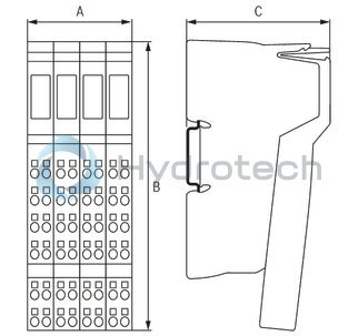
Dimensions
|
Type |
R-IB IL 24 IOL 4 DI 12-PAC | |
|
A |
mm |
48.8 |
|
B |
mm |
140.5 |
|
C |
mm |
71.5 |
|
Note on dimensions |
The depth applies when using a support rail TH 35-7.5 (acc. to EN 60715). | |