

BOSCH REXROTH
R911171944
$1,409.07 USD
- BOSCH REXROTH
- Material:R911171944
- Model:R-ILPNBKDI8DO4-PAC
Quantity in stock: 0
The Bosch Rexroth R-IL PN BK DI8 DO4-PAC (R911171944) is a state-of-the-art bus coupler designed to seamlessly integrate with PROFINET networks, facilitating the acquisition and output of digital signals within an automation environment. This device enables the connection of up to 63 Inline participants, allowing for extensive flexibility and expansion in system configurations. The R-IL PN BK DI8 DO4-PAC serves as a crucial node within the network, effectively creating a single station that can support a maximum of 61 local bus participants, with the bus coupler itself being recognized as the first participant and its inputs/outputs as the second. This model is particularly effective when deployed in systems requiring reliable real-time communication and is well-suited for applications where digital signal processing is paramount. Its design ensures that it can be easily integrated into existing setups without significant alterations, thereby providing a cost-effective solution for system upgrades or expansions. The capability to connect multiple devices makes this bus coupler an invaluable component in complex automation tasks where coordination between various sensors, actuators, and other Inline participants is necessary for efficient operation.
Inline connector
The modular, compact equipment configuration of the I/O systems from Rexroth offers you maximum flexibility for the cost-effective implementation of your individual machine concepts. The I/O modules have robust design and mechanics, are easy to use, have a quick reaction time and are quick to install – both in the control cabinet and in the field. Open communication standards allow you perfect integration of the I/O modules with maximum availability.
Unpacked Weight: 0.34 kg
This description is effective as of firmware version 2.30.
The bus coupler is the connection between a PROFINET network and the Inline installation system. It is also used to acquire and output digital signals. You can use the bus coupler to connect up to 61 Inline participants, anywhere, to an existing PROFINET network. The bus coupler and the Inline participants form one station with a maximum 63 local bus participants, whereby the inputs and outputs for the bus coupler are to be regarded as the first and second local bus participant.
| Data Sheet | Download Data Sheet |
| 3D CAD | Download 3D CAD |
| Manual | Download Manual |
| Air pressure (operation) | 70-106 kPa (up to 3,000 m above sea level) |
| Total current | 2 |
| Width | 80 |
| Short circuit protection, overload protection of the outputs | Free-wheeling circuit in the output driver |
| Productgroup ID | 4,6 |
| Height | 120 |
| International protection code | IP20 |
| Permissible air humidity (storage) | 10-95 |
| Communication | Profinet |
| Permissible air humidity (transport) | 10-95 |
| Number of channels | 12 |
| Connection type | Zugfederanschluss |
| Connection techniques | 2-, 3-Leitertechnik |
| Depth | 71.5 |
| Weight | 0.34 |
| Ambient temperature (during operation) | -25-55 |
| Ambient temperature (storage and transport) | -40-85 |
| Conductor cross-section | Rigid: 0.08-0.5 mm²,Flexible: 0.08-0.5 mm²,AWG: 28 ... 16 |
General data
|
Type |
R-IL PN BK DI8 DO4-PAC | |
|
Color |
Gray | |
|
Weight 1) |
g |
375 |
|
Ambient temperature (operation) 2) |
-25 °C ... +55 °C | |
|
Ambient temperature (storage/transport) |
-40 °C ... +85 °C | |
|
Permissible relative humidity (operation) |
10 % ... 95 % acc. to DIN EN 61131-2 | |
|
Permissible relative humidity (storage/transport) |
10 % ... 95 % acc. to DIN EN 61131-2 | |
|
Air pressure (operation) |
70 kPa ... 106 kPa (up to 3000 m above sea level) | |
|
Air pressure (storage/transport) |
70 kPa ... 106 kPa (up to 3000 m above sea level) | |
|
Protection type |
IP20 | |
|
Protection class |
III, IEC 61140, EN 61140, VDE 0140-1 | |
| 1) | Including plug |
| 2) | Observe derating |
Connection data
|
Type |
R-IL PN BK DI8 DO4-PAC | |
|
Designation |
Inline connection plug | |
|
Connection type |
Spring-cage connection | |
|
Conductor cross-section solid/flexible/AWG |
0.08 mm² ... 1.5 mm² 0.08 mm² ... 1.5 mm² 28 ... 16 |
|
|
Permissible cable length |
m |
30 |
Interface fieldbus
|
Type |
R-IL PN BK DI8 DO4-PAC | |
|
Number of interfaces |
2 | |
|
Connection type |
RJ45 socket, autonegotiation | |
|
Transmission speed 1) |
100 MBit/s | |
|
Transfer physics |
Ethernet in RJ45 twisted pair - - - |
|
|
Transmission length |
m |
≤ 100 |
| 1) | Acc. to PROFINET standard |
Interface local bus
|
Type |
R-IL PN BK DI8 DO4-PAC | |
|
Connection type |
Inline data jumper | |
|
Transmission speed |
500 kbits/s, 2 Mbits/s (automatic detection, no mixed system) | |
System boundaries
|
Type |
R-IL PN BK DI8 DO4-PAC | |
|
Number of process data |
Max. 488 bytes (max. 244 bytes IN - max. 244 bytes OUT) | |
|
Process data IN for side-by-side I/O modules |
byte |
244 |
|
Process data OUT for side-by-side I/O modules |
byte |
244 |
|
Number of supported participants per station |
≤ 63 | |
|
Number of subsequent local bus participants |
Max. 61 (I/Os on board are two participants) | |
|
Number of participants with parameter channel |
≤ 16 | |
PROFINET
|
Type |
R-IL PN BK DI8 DO4-PAC | |
|
Device function |
PROFINET-Device | |
|
Update rate |
ms |
≥ 1 |
Supported protocols
|
Type |
R-IL PN BK DI8 DO4-PAC | |
|
Supported protocols |
PROFINET, PDev, TFTP, ICMP, LLDP | |
Supply of module electronics
|
Type |
R-IL PN BK DI8 DO4-PAC | |
|
Connection type |
Spring-cage connection | |
|
Designation |
Bus coupler supply UBK; from the bus coupler supply, the logic supply UL (7.5 V) and the analog supply UANA (24 V) are generated. | |
|
Supply voltage |
V DC |
24 |
|
Supply voltage range |
19.2 V DC ... 30 V DC (including all tolerances, including ripple) | |
|
Typical current consumption from UBK |
mA |
138 |
|
Maximum current consumption from UBK |
A |
0.91 |
|
Power dissipation |
Typ. 3 W (device total) | |
|
Overvoltage/reverse polarity protection supply voltage |
35 V, suppressor diode | |
Inline potentials/performance balance
|
Type |
R-IL PN BK DI8 DO4-PAC | |
|
Supply to the main circuit UM |
V DC |
24 |
|
Supply voltage range UM |
19.2 V DC ... 30 V DC (including all tolerances, including ripple) | |
|
Power supply to UM |
Max. 8 A (total of UM + US) | |
|
Current consumption from UM |
A |
≤ 8 |
|
Logic voltage UL |
7.5 V DC ±5 % | |
|
Power supply to UL |
A |
≤ 0.8 |
|
Peripheral supply voltage UANA |
V DC |
24 |
|
Supply voltage range UANA |
19.2 V DC ... 30 V DC (including all tolerances, including ripple) | |
|
Power supply to UANA |
A |
≤ 0.5 |
|
Typical current consumption from UBK |
mA |
138 |
|
Maximum current consumption from UBK |
A |
0.91 |
|
Segment supply voltage US |
V DC |
24 |
|
Supply voltage range US |
19.2 V DC ... 30 V DC (including all tolerances, including ripple) | |
|
Power supply to US |
Max. 8 A (total of UM + US) | |
|
Current consumption from US |
A |
≤ 8 |
|
Power dissipation |
Typ. 3 W (device total) | |
Digital inputs
|
Type |
R-IL PN BK DI8 DO4-PAC | |
|
Number of digital inputs |
Max. 8 (EN 61131-2 type 1) | |
|
Connection type |
Inline connection plug | |
|
Connectivity technology |
2-, 3-wire | |
|
Nominal input voltage |
V DC |
24 |
|
Nominal input current |
mA |
3 |
|
Current profile |
Limited to maximum 3 mA | |
|
Input voltage range "0" signal |
-30 V DC ... 5 V DC | |
|
Input voltage range "1" signal |
15 V DC ... 30 V DC | |
|
Delay time upon signal change from 0 to 1 |
Typ. 5 ms | |
|
Delay time upon signal change from 1 to 0 |
Typ. 5 ms | |
|
Permissible cable length to sensor |
m |
100 |
|
Reverse polarity protection |
Reverse polarity protection diode | |
Digital outputs
|
Type |
R-IL PN BK DI8 DO4-PAC | ||
|
Number of digital outputs |
4 | ||
|
Connection type |
Inline connection plug | ||
|
Connectivity technology |
2-, 3-wire | ||
|
Nominal output voltage |
24 V DC | ||
|
Output current per channel |
mA |
≤ 500 | |
|
Nominal load ohmic |
W |
12 | |
|
Nominal load lamps |
W |
12 | |
|
Nominal load inductive |
1.2 H; 48 Ω |
VA |
12 |
|
Typical signal delay |
ms |
1.2 | |
|
Signal delay upon power-up of ohmic nominal load 1) |
µs |
≤ 50 | |
|
Signal delay upon turning off an ohmic nominal load 1) |
µs |
≤ 250 | |
|
Maximum switching frequency for inductive nominal load |
1.2 H; 48 Ω |
Hz |
0.5 |
|
Response time upon short-circuit |
ms |
1.2 | |
|
Behavior when the voltage is switched off |
The output follows delayed by 1.2 ms after voltage drop. | ||
|
Limited inductive cut-off voltage |
V |
≈ - 30 | |
|
Output current in deactivated state 2) |
μA |
≤ 10 | |
|
Behavior for overload |
Automatic restart | ||
|
Inductive overload |
Output can be destroyed | ||
|
Reverse voltage protection from short pulses |
Reverse voltage protection | ||
|
Resistance to permanently generated reverse voltage |
A |
≤ 2 | |
|
Overcurrent cutoff |
A |
≥ 0.7 | |
|
Short-circuit protection, overload protection of the outputs |
Freewheeling circuit in the output driver | ||
| 1) | With 0.5 A load |
| 2) | In the unloaded state, a voltage can also be measured at an output that is not set. |
Error messages to the higher-level control or computer system
|
Type |
R-IL PN BK DI8 DO4-PAC | |
|
Error message |
Short-circuit/overload of digital outputs Failure in sensor supply Failure in actuator supply |
|
Mechanical tests
|
Type |
R-IL PN BK DI8 DO4-PAC | |
|
Vibration resistance 1) |
g |
5 |
|
Shock 2) |
25 g, 11 ms duration, semi-sinusoidal shock pulse | |
| 1) | Acc. to EN 60068-2-6/IEC 60068-2-6 |
| 2) | Acc. to EN 60068-2-27/IEC 60068-2-27 |
Conformity
|
Type |
R-IL PN BK DI8 DO4-PAC | ||
|
Conforms with |
|||
|
Testing of interference immunity acc. to EN 61000-6-2 |
Discharge of static electricity (ESD) |
Criterion B; 6 kV contact discharge; 8 kV air discharge acc. to EN 61000-4-2/IEC 61000-4-2 | |
|
Electro-magnetic fields |
Criterion A; field strength: 10 V/m acc. to EN 61000-4-3/IEC 61000-4-3 | ||
|
Fast transients (burst) |
Criterion A; all interfaces 1 kV; criterion B; all interfaces 2 kV acc. to EN 61000-4-4/IEC 61000-4-4 | ||
|
Transient overvoltage (surge) |
Criterion B; supply lines DC: ±0.5 kV/±0.5 kV (symmetric/asymmetric); fieldbus cable shielding: ±1 kV acc. to EN 61000-4-5/IEC 61000-4-5 | ||
|
Line-fed disturbances |
Criterion A; test voltage 10 V acc. to EN 61000-4-6/IEC 61000-4-6 | ||
|
Testing of disturbance transmission acc. to EN 61000-6-4 |
Testing of line-fed disturbance transmission |
Class A acc. to EN 55011 | |
|
Approvals |
|
The current approvals can be found at www.boschrexroth.com. |
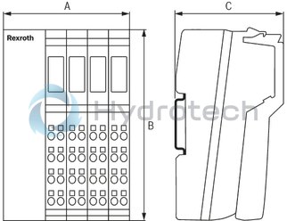
Dimensions
|
Type |
R-IL PN BK DI8 DO4-PAC | |
|
A |
mm |
80 |
|
B |
mm |
120 |
|
C |
mm |
71.5 |
|
Note on dimensions |
The depth applies when using a support rail TH 35-7.5 (acc. to EN 60715). | |