

BOSCH REXROTH
R911170874
$3,594.02 USD
- BOSCH REXROTH
- Material:R911170874
- Model:R-ILBS3AI4A02
Quantity in stock: 0
The Bosch Rexroth R-ILB S3 AI4 A02 (R911170874) is a high-performance module engineered for seamless integration into a SERCOS III network. This module is specifically designed to handle the acquisition of analog input signals, as well as to provide reliable output of analog signals. Its capabilities ensure precise and efficient processing of data within automated systems, making it a critical component for various applications that require accurate real-time analog signal handling. The R-ILB S3 AI4 A02 module's advanced features allow it to support complex operations in automation environments. With four analog inputs, the module can gather data from multiple sources simultaneously, ensuring comprehensive monitoring and control. This versatility is essential for tasks that demand high levels of accuracy and synchronization, such as in precision manufacturing processes or quality control systems. Furthermore, the module's ability to output analog signals enables it to interface with a range of devices and machinery that rely on analog input for operation. This feature makes the R-ILB S3 AI4 A02 an indispensable tool for facilitating communication between digital control systems and analog-driven components within an industrial setting. Overall, the Bosch Rexroth R-ILB S3 AI4 A02 (R911170874) stands out as a robust solution for any application demanding high fidelity in signal acquisition and output within a SERCOS III network infrastructure. Its design ensures reliability and performance that meet the rigorous standards expected in modern automated systems.
The R-ILB S3 AI4 AO2 module is designed for use within a SERCOS III network. It is used to acquire analog input signals and to output analog signals.
General data
|
Type |
R-ILB S3 AI4 AO2 | |
|
Weight 1) |
g |
465 |
|
Operating mode |
Sercos III process data operation | |
|
Sensor connection type |
2-, 3-, 4-wire technology (shielded) | |
|
Actuator connection type |
2-, 3-, 4-wire technology (shielded) | |
|
Ambient temperature (operation) |
-25 °C ... +60 °C | |
|
Ambient temperature (storage/transport) |
-25 °C ... +85 °C | |
|
Permissible relative humidity (operation) |
10 % ... 95 % acc. to DIN EN 61131-2 | |
|
Permissible relative humidity (storage/transport) |
10 % ... 95 % acc. to DIN EN 61131-2 | |
|
Air pressure (operation) |
70 kPa … 108 kPa (up to 3,500 m above sea level) | |
|
Air pressure (storage/transport) |
70 kPa … 108 kPa (up to 3,500 m above sea level) | |
|
Protection type |
IP20, IEC 60529 | |
|
Protection class |
III, IEC 61140 | |
|
Clearances and creepage distances |
Acc. to DIN VDE 0110/IEC 60664, IEC 60664A, DIN VDE 0160/EN 50178/IEC 62103 | |
|
Housing material |
Plastic, PVC-free, PBT, self-extinguishing (V0) | |
|
Degree of contamination 2) |
2; dewing in operation is not permitted! | |
|
Overvoltage class |
II | |
| 1) | Including plug |
| 2) | Acc. to EN 60664-1/IEC 60664-1, EN 61131-2/IEC 61131-2 |
Connection data
|
Type |
R-ILB S3 AI4 AO2 | |
|
Permissible cable length 1) |
m |
250 |
| 1) | The information relates to nominal operation in compliance with the installation regulations and refer to the following reference line type: Shielded power plant line: LiYCY; 2 x 2 x 0.5 mm2; VDE0812 |
Interface fieldbus
|
Type |
R-ILB S3 AI4 AO2 | |
|
Number of interfaces |
2 | |
|
Connection type |
RJ45 plug; shielding via parallel connection of R, C, and VDR | |
|
Connectivity technology |
Sercos III | |
|
Transmission speed |
100 MBit/s | |
24 V module supply (logic and sensor supply)
|
Type |
R-ILB S3 AI4 AO2 | ||
|
Rated value |
V DC |
24 | |
|
Tolerance |
-15 %/+20 % acc. to EN 61131-2 | ||
|
Ripple 1) |
% |
± 5 | |
|
Permissible range |
19.2 ... 30 V DC | ||
|
Current consumption from UL |
See "Current consumption from UL and US" | ||
|
Current consumption from US |
See "Current consumption from UL and US" | ||
|
Power dissipation in UL |
See "Power consumption from UL and US" | ||
|
Power dissipation in US |
See "Power consumption from UL and US" | ||
|
Protection measures |
For UL |
Transient overload protection via diverter, serial reverse polarity protection | |
|
For US |
Transient overload protection via diverter, serial reverse polarity protection, short-circuit protection by channel with single-channel diagnostics | ||
|
Connection |
Via power supply plug | ||
|
Diagnostics |
Failure indication via group error LED at PWR slot; single-channel failure indication via LED at slot for the sensors - - - - |
||
| 1) | Acc. to EN 61131-2 |
Electronically-protected initiator supply UIS (via feed from US)
|
Type |
R-ILB S3 AI4 AO2 | |
|
Nominal value UIS |
24 V DC | |
|
Nominal current IIS per channel |
mA |
50 |
|
Guarantee |
Internal, channel electronic fuse, short-circuit protected with single-channel diagnostics - - - |
|
Analog inputs
|
Type |
R-ILB S3 AI4 AO2 | |
|
Number of analog inputs 1) |
4 | |
|
Data formats |
IB IL | |
|
Measurement representation |
16 bits (15 bits + sign) - - - - - |
|
|
Filtering |
RFI filtering/passive TP 1st order | |
|
Filter time of the A/D converter |
4.5 ms (default) or 1.1 ms; configurable for each channel | |
|
Conversion time for the A/D converter |
µs |
180 |
|
Cut-off frequency (–3 dB) of the input filter |
120 Hz (for 4.5-ms-filter default setting) or 450 Hz (for 1.1-ms filter) | |
|
Transient protection |
Via diverter | |
|
Signal connection type |
2-, 3- and 4-wire technology, shielded cable, twisted pair | |
|
Overload protection |
Yes, minimum ±30 V DC | |
| 1) | Analog differential inputs |
Analog differential voltage inputs
|
Type |
R-ILB S3 AI4 AO2 | |
|
Number of inputs |
4 | |
|
Input range |
0 V … 10 V; ± 10 V 0 V … 5 V; ± 5 V - - |
|
|
Input resistance |
kΩ |
276 |
|
Open circiut response |
Goes to 0 V | |
|
Maximum permissible voltage between analog voltage inputs and analog mass (UCM) |
V DC |
± 50 |
Analog differential current inputs
|
Type |
R-ILB S3 AI4 AO2 | |
|
Number of inputs |
4 | |
|
Input range |
0 mA … 20 mA; ± 20 mA 4 mA … 20 mA - |
|
|
Input resistance |
Ω |
107 |
|
Open circiut response |
Goes to 0 mA | |
|
Maximum permissible current per current input |
Electronically overload protected | |
|
Overload protection at the analog current inputs |
Yes, minimum ±30 V DC | |
Analog RTD inputs
|
Type |
R-ILB S3 AI4 AO2 | |
|
Number of inputs |
4 | |
|
Input range |
Pt100, Pt500, Pt1000, Ni100, Ni1000, Ni1000 L&S, 0 Ω ... 3200 Ω, 0 Ω ... 9500 Ω | |
|
Sensor supply current |
mA |
231 |
Analog outputs
|
Type |
R-ILB S3 AI4 AO2 | ||
|
Number of analog outputs |
2 | ||
|
Signal connection type |
2-, 3- and 4-wire technology, shielded cable, twisted pair | ||
|
Output voltage range |
0 V ... 10 V; ±10 V; 0 V ... 5 V; ±5 V | ||
|
Output current range |
0 mA ... 20 mA; ±20 mA; 4 mA ... 20 mA | ||
|
Data formats |
IB IL | ||
|
Measurement representation |
16 bits (15 bits + sign) - - - - - |
||
|
Conversion time of the D/A converter |
µs |
70 | |
|
Resolution of the D/A converters |
bits |
16 | |
|
Output load |
Voltage output RLmin |
kΩ |
2 |
|
Current output RLB |
0 Ω ... 500 Ω | ||
|
Transient protection |
Internal via diverter | ||
|
Short-circuit protection |
Voltage output |
Permanently electronically short-circuit protected | |
|
Current output |
Permanently electronically short-circuit protected | ||
|
Free switching function |
Internal electronic | ||
|
Optical displays |
5 % output LED, by channel | ||
Electrical isolation/insulation of the voltage ranges
|
Type |
R-ILB S3 AI4 AO2 | |
|
Test distance |
Test voltage | |
|
Sercos III/logic |
500 V AC, 50 Hz, 1 min. | |
|
Sercos III / analog peripherals |
500 V AC, 50 Hz, 1 min. | |
|
Sercos III/logic supply UL |
500 V AC, 50 Hz, 1 min. | |
|
Sercos III/initiator supply US |
500 V AC, 50 Hz, 1 min. | |
|
Sercos III/function earth |
500 V AC, 50 Hz, 1 min. | |
|
Logic / analog peripherals |
500 V AC, 50 Hz, 1 min. | |
|
Logic/logic supply UL |
500 V AC, 50 Hz, 1 min. | |
|
Logic/initiator supply US |
500 V AC, 50 Hz, 1 min. | |
|
Logic/function earth |
500 V AC, 50 Hz, 1 min. | |
|
Analog peripherals/logic supply UL |
500 V AC, 50 Hz, 1 min. | |
|
Analog peripherals/initiator supply US |
500 V AC, 50 Hz, 1 min. | |
|
Analog peripherals/function earth |
500 V AC, 50 Hz, 1 min. | |
|
Logic supply UL/initiator supply US |
500 V AC, 50 Hz, 1 min. | |
|
Logic supply UL/function earth |
500 V AC, 50 Hz, 1 min. | |
|
Initiator supply US/function earth |
500 V AC, 50 Hz, 1 min. | |
Current consumption from UL and US
| Typical | Maximum | |||
|
Current consumption from UL |
No load of outputs and AI operation |
mA |
160 | 190 |
|
RTD nominal load |
mA |
160 | 190 | |
|
AO-U nominal load (UOUT1 and UOUT2 = 10 V with RL = 2 kΩ) |
mA |
175 | 200 | |
|
AO-I nominal load (IOUT1 and IOUT2 = 20 mA with RL = 0 Ω) |
mA |
195 | 220 | |
|
Current consumption from US |
IiS = 0 mA (no load) |
mA |
12 | 20 |
|
IiS = 4 x 20 mA (nominal load) |
mA |
92 | 100 | |
|
IiS = 4 x 50 mA (maximum full load) |
mA |
212 | 220 | |
|
Total current consumption from UL and US |
No load of outputs and AI operation; IiS = 0 mA (no load) |
mA |
172 | 210 |
|
AO-U nominal load and AI nominal load; IiS = 4 x 20 mA |
mA |
267 | 300 | |
|
AO-I nominal load and AI nominal load; IiS = 4 x 20 mA |
mA |
287 | 320 | |
|
AO-I nominal load and AI full load; IiS = 4 x 50 mA |
mA |
407 | 440 | |
Power consumption from UL and US
(current consumption from the voltages UL, US; data for nominal operation (UL = 24 V; US = 24 V without load), full load as for nominal operation, but with loaded US)
| Typical supply current | Typical power dissipation | ||||
|
Power supply of the control panel power supply P24V_power supply typical in U nominal operation |
AO load: U operation of the analog outputs (UOUT1,2 = 10 V with RL = 10 K) |
IIS = 0 mA |
190 mA | 4.56 W | |
|
Power supply of the control panel power supply P24V_power supply typical in I nominal operation |
AO load: I operation of the analog outputs (IOUT1,2 = 20 mA, with Rb = 0 Ω) |
IIS = 0 mA |
215 mA | 5.16 W | |
|
Power supply of the control panel power supply P24V_power supply typical in nominal operation |
AO load: U operation of the analog outputs (UOUT1,2 = 10 V with RL = 10 K) |
IIS = 4 x 20 mA |
270 mA | 6.48 W | |
|
Power supply of the control panel power supply P24V_power supply typical under full load |
AO load: I operation of the analog outputs (IOUT1,2 = 20 mA, with Rb = 0 Ω) |
IIS = 4 x 20 mA |
290 mA | 6.96 W | |
|
Power supply of the control panel power supply P24V_power supply typical in nominal operation |
AO load: U operation of the analog outputs (UOUT1,2 = 10 V with RL = 10 K) |
IIS = 4 x 50 mA |
390 mA | 9.36 W | |
|
Power supply of the control panel power supply P24V_power supply typical under full load |
AO load: I operation of the analog outputs (IOUT1,2 = 20 mA, with Rb = 0 Ω) |
IIS = 4 x 50 mA |
410 mA | 9.84 W | |
Limit values for temperature measurement
|
Sensor type |
Nominal range lower limit |
Nominal range upper limit |
|
|
Pt DIN |
°C |
- 200 | + 850 |
|
Ni DIN |
°C |
- 60 | + 180 |
|
Ni1000 L&S |
°C |
- 50 | + 160 |
Tolerances at TU = 25 °C
| Absolute, typical | Absolute, maximum | Relative, typical | Relative, maximum | |||
|
Measurement range AI |
0 V ... 5 V ±5 V |
± 5 mV | ± 20 mV | 0.1 % | ± 0.4 % | |
|
0 V ... 10 V ±10 V |
± 6 mV | ± 25 mV | 0.06 % | ± 0.25 % | ||
|
0 mA ... 20 mA ±20 mA |
± 12 μA | ± 50 μA | 0.06 % | ± 0.25 % | ||
|
4 mA ... 20 mA ±20 mA |
± 12 μA | ± 50 μA | 0.06 % | ± 0.25 % | ||
|
Pt100 (-200 °C ... +850 °C) |
± 0.5 K | ± 2 K | 0.06 % | ± 0.25 % | ||
|
Pt500 (-200 °C ... +850 °C) |
± 0.4 K | ± 1.6 K | 0.04 % | ± 0.19 % | ||
|
Pt1000 (-200 °C ... +850 °C) |
± 0.4 K | ± 1.6 K | 0.03 % | ± 0.19 % | ||
|
Ni100 (-60 °C ... +180 °C) |
± 0.5 K | ± 1.9 K | 0.28 % | ± 1.1 % | ||
|
Ni1000 (-60 °C ... +180 °C) |
± 0.2 K | ± 0.9 K | 0.12 % | ± 0.5 % | ||
|
Ni1000 L&S (-50 °C ... +160 °C) |
± 0.2 K | ± 3 K | ± 0.13 % | ± 0.6 % | ||
|
0 Ω ... 3200 Ω |
± 0.6 Ω | ± 2.75 Ω | 0.02 % | ± 0.1 % | ||
|
0 Ω ... 9500 Ω |
± 2 Ω | ± 12 Ω | 0.02 % | ± 0.13 % | ||
|
Output range AO |
0 V ... 5 V ±5 V |
± 10 mV | ± 30 mV | 0.1 % | ± 0.3 % | |
|
0 V ... 10 V ±10 V |
± 10 mV | ± 30 mV | 0.1 % | ± 0.3 % | ||
|
0 mA ... 20 mA ±20 mA |
± 20 μA | ± 60 mA | 0.1 % | ± 0.3 % | ||
|
4 mA ... 20 mA ±20 mA |
± 20 μA | ± 60 mA | 0.1 % | ± 0.3 % | ||
Tolerance and temperature behavior at TU = -25 °C ... +60 °C
| Drift, typical | Drift, maximum | |||
|
Measurement range AI |
0 V ... 5 V ±5 V |
ppm/K |
± 25 | ± 55 |
|
0 V ... 10 V ±10 V |
ppm/K |
± 25 | ± 55 | |
|
0 mA ... 20 mA ±20 mA |
ppm/K |
± 20 | ± 50 | |
|
4 mA ... 20 mA ±20 mA |
ppm/K |
± 20 | ± 50 | |
|
Pt100 (-200 °C ... +850 °C) |
ppm/K |
± 50 | ± 100 | |
|
Pt500 (-200 °C ... +850 °C) |
ppm/K |
± 30 | ± 60 | |
|
Pt1000 (-200 °C ... +850 °C) |
ppm/K |
± 20 | ± 50 | |
|
Ni100 (-60 °C ... +180 °C) |
ppm/K |
± 50 | ± 100 | |
|
Ni1000 (-60 °C ... +180 °C) |
ppm/K |
± 20 | ± 50 | |
|
Ni1000 L&S (-50 °C ... +160 °C) |
ppm/K |
± 20 | ± 60 | |
|
0 Ω ... 3200 Ω |
ppm/K |
± 20 | ± 60 | |
|
0 Ω ... 9500 Ω |
ppm/K |
± 15 | ± 30 | |
|
Output range AO |
0 V ... 5 V ±5 V |
ppm/K |
± 40 | ± 90 |
|
0 V ... 10 V ±10 V |
ppm/K |
± 40 | ± 90 | |
|
0 mA ... 20 mA ±20 mA |
ppm/K |
± 40 | ± 90 | |
|
4 mA ... 20 mA ±20 mA |
ppm/K |
± 40 | ± 90 | |
|
Formula for calculating the tolerance under temperature influence |
||
|
Typical temperature drift |
Drifttyp = Δθ x TCtyp x MREV |
|
|
where: |
||
|
Drifttyp |
Typical temperature drift |
|
|
Δθ |
Temperature difference between the ambient temperature of module Ta and +25 °C |
|
|
TCtyp |
Temperature coefficient typically in ppm/C |
|
|
MREV |
Measurement range end value (e.g. +850 °C at Pt100) |
|
|
Maximum temperature drift |
Driftmax = Δθ x TCmax x MREV |
|
|
where: |
||
|
Driftmax |
Maximum temperature drift |
|
|
Δθ |
Temperature difference between the ambient temperature of module Ta and +25 °C |
|
|
TCmax |
Temperature coefficient maximum in ppm/C |
|
|
MREV |
Measurement range end value (e.g. +850 °C at Pt100) |
|
|
Example |
Sensor = Pt100; ambient temperature Ta = +40 °C |
|
Tolerances under the influence of electromagnetic interference
|
Analog input power |
Analog input voltage |
Analog input RTD |
Analog output power |
Analog output voltage |
|||
|
Electro-magnetic fields |
Acc. to EN 61000-4-3/IEC 61000-4-3 |
% |
< ± 1.5 | < ± 4 | - | < ± 0.5 | < ± 0.5 |
|
Fast transients (burst) |
Acc. to EN 61000-4-4/IEC 61000-4-4 |
- | - | - | - | - | |
|
Line-fed disturbances |
Acc. to EN 61000-4-6/IEC 61000-4-6 |
% |
- | - | < ± 2 | - | - |
Signal rise times
| 10 % ... 90 % | 0 % ... > 99 % | ||
|
Voltage output 0 V ... 10 V (typical data) |
|||
|
Ohmic load RL = 2 kΩ |
µs |
160 | 240 |
|
Ohmic/capacitive load RL = 2 kΩ/CL = 10 nF |
µs |
160 | 240 |
|
Ohmic/capacitive load RL = 2 kΩ/CL = 220 nF |
µs |
170 | 240 |
|
Ohmic/inductive load RL = 2 kΩ/LL = 3.3 mH |
µs |
170 | 240 |
|
Power output 0 mA ... 20 mA (typical data) |
|||
|
Ohmic load RL = 500 Ω |
µs |
450 | 730 |
|
Ohmic/capacitive load RL = 500 Ω/CL = 10 nF |
µs |
460 | 750 |
|
Ohmic/capacitive load RL = 500 Ω/CL = 220 nF |
770 µs | 1.3 ms | |
|
Ohmic/inductive load RL = 500 Ω/LL = 3.3 mH |
610 µs | 1.1 ms | |
|
Ohmic/capacitive load RL = 50 Ω/CL = 100 nF |
ms |
11 | 20.7 |
|
Power output 4 mA ... 20 mA (typical data) |
|||
|
Ohmic load RL = 500 Ω |
µs |
400 | 810 |
|
Ohmic/capacitive load RL = 500 Ω/CL = 10 nF |
µs |
470 | 840 |
|
Ohmic/capacitive load RL = 500 Ω/CL = 220 nF |
800 µs | 1.4 ms | |
|
Ohmic/inductive load RL = 500 Ω/LL = 3.3 mH |
µs |
590 | 990 |
Mechanical tests
|
Type |
R-ILB S3 AI4 AO2 | |
|
Vibration resistance 1) |
Load 5 g, 2.5 h per spatial direction | |
|
Shock 2) |
Load 30 g for 11 ms, half sinusoidal wave, three shocks per spatial direction and orientation | |
|
Broadband noise 3) |
Load 0.78 g, 2.5 h per spatial direction | |
| 1) | Acc. to EN 60068-2-6/IEC 60068-2-6 |
| 2) | Acc. to EN 60068-2-27/IEC 60068-2-27 |
| 3) | Acc. to EN 60068-2-64/IEC 60068-2-64 |
Conformity
|
Type |
R-ILB S3 AI4 AO2 | ||
|
Conforms with |
|||
|
Testing of interference immunity acc. to EN 61000-6-2 |
Discharge of static electricity (ESD) |
Criterion B; 6 kV contact discharge; 8 kV air discharge acc. to EN 61000-4-2/IEC 61000-4-2 | |
|
Electro-magnetic fields |
Criterion A; field strength: 10 V/m acc. to EN 61000-4-3/IEC 61000-4-3 | ||
|
Fast transients (burst) |
Criterion B; remote bus: 2 kV; voltage supply: 2 kV; I/O lines: 2 kV; criterion A; all interfaces: 1 kV acc. to EN 61000-4-4/IEC 61000-4-4 | ||
|
Transient overvoltage (surge) |
Criterion B; supply lines DC: ±0.5 kV/±0.5 kV (symmetric/asymmetric); signal lines: ±0.5 kV/±0.5 kV (symmetric/asymmetric) acc. to EN 61000-4-5/IEC 61000-4-5 | ||
|
Line-fed disturbances |
Criterion A; test voltage 10 V acc. to EN 61000-4-6/IEC 61000-4-6 | ||
|
Testing of disturbance transmission acc. to EN 61000-6-4 |
Testing of line-fed disturbance transmission |
Class A acc. to EN 55011 | |
|
Approvals |
|
The current approvals can be found at www.boschrexroth.com. |
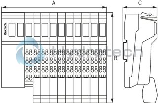
Dimensions
|
Type |
R-ILB S3 AI4 AO2 | |
|
A |
mm |
156 |
|
B |
mm |
141 |
|
C |
mm |
57 |
|
Note on dimensions |
The depth applies when using a support rail TH 35-7.5 (acc. to EN 60715). | |