

BOSCH REXROTH
R911170788
$689.99 USD
- BOSCH REXROTH
- Material:R911170788
- Model:R-IBILCNT-PAC
Quantity in stock: 0
The Bosch Rexroth R-IB IL CNT-PAC (R911170788) is a high-performance counter module designed for integration within an Inline station. This advanced counter, commonly referred to simply as a counter module, is specifically engineered to acquire and process rapid pulse sequences emanating from various sensors. It boasts a robust set of features including a counter input source for capturing pulses, a control input gate for managing signal processing, and a freely parameterizable switching output which operates independently from the assembly setup. This configuration ensures swift response times that are not influenced by the bus system or the connected controller. The R-IB IL CNT-PAC module is versatile in its applications, offering four distinct operating modes to cater to different requirements: frequency measurement for monitoring vibrations or rotational speeds; event counting for items or occurrences; time measurement for duration tracking; and pulse generation for creating pulse sequences. The flexibility of these modes makes it suitable for a wide range of tasks that require precise pulse detection and handling. Compatibility with sensors is broad, as the module can connect to sensors with both 24 V DC supply and other voltage levels. Its switching output is capable of delivering up to 500 mA of current, ensuring reliable operation even with high-demand devices. The module comes complete with necessary accessories such as a connection plug and labeling field, simplifying installation and maintenance while promoting organized cable management and clear identification within complex systems. The R-IB IL CNT-PAC stands out due to its ability to provide fast reaction times independent of the control system's communication bus, making it an ideal choice for applications where timing and precision are critical.
Inline connector
The modular, compact equipment configuration of the I/O systems from Rexroth offers you maximum flexibility for the cost-effective implementation of your individual machine concepts. The I/O modules have robust design and mechanics, are easy to use, have a quick reaction time and are quick to install – both in the control cabinet and in the field. Open communication standards allow you perfect integration of the I/O modules with maximum availability.
Unpacked Weight: 0.17 kg
This module is a counter module that is assigned for use within an Inline station. The counter module is also called a "counter". The counter module acquires and processes rapid pulse sequences from sensors. It comes with a counter input (source), a control input (gate), and a freely parameterizable switching output that is set apart from the assembly. This allows fast reaction times that do not depend on the bus and controller. The module can be operated in four different operating modes. These are frequency measurement, event counting, time measurement, and pulse generation (pulse generator). Sensors with a 24 V DC supply and 5 V DC supply can be connected to the module. The switching output delivers a maximum current of 500 mA.
| Data Sheet | Download Data Sheet |
| Manual | Download Manual |
| Air pressure (operation) | 70-106 kPa (up to 3,000 m above sea level) |
| Width | 24.4 |
| Productgroup ID | 4,6 |
| Height | 136.8 |
| International protection code | IP20 |
| Permissible air humidity (storage) | 10-95 |
| Permissible air humidity (transport) | 10-95 |
| Number of channels | 5 |
| Connection type | Zugfederanschluss |
| Connection techniques | 2-, 3-Leitertechnik |
| Depth | 71.5 |
| Weight | 0.17 |
| Ambient temperature (during operation) | -25-55 |
| Ambient temperature (storage and transport) | -25-85 |
| Conductor cross-section | Rigid: 0.2-1.5 mm²,Flexible: 0.2-1.5 mm²,AWG: 24 ... 16 |
General data
|
Type |
R-IB IL CNT-PAC | |
|
Weight 1) |
g |
110 |
|
Operating mode |
Process data operation with 4 bytes | |
|
Basic functionality |
Frequency measurement, pulse count, time measurement, pulse generator | |
|
24 V sensor connection type |
2-, 3-wire technology | |
|
5 V sensor connection type |
2-wire technology with shielding and external 5 V supply | |
|
Actuator connection type |
2-wire technology | |
|
Ambient temperature (operation) |
-25 °C ... +55 °C | |
|
Ambient temperature (storage/transport) |
-25 °C ... +85 °C | |
|
Permissible relative humidity (operation) |
10 % ... 95 % acc. to DIN EN 61131-2 | |
|
Permissible relative humidity (storage/transport) |
10 % ... 95 % acc. to DIN EN 61131-2 | |
|
Air pressure (operation) |
70 kPa ... 106 kPa (up to 3000 m above sea level) | |
|
Air pressure (storage/transport) |
70 kPa ... 106 kPa (up to 3000 m above sea level) | |
|
Protection type |
IP20, DIN 40050, IEC 60529 | |
|
Protection class |
III, VDE 0106, IEC 60536, DIN 57106-1 | |
| 1) | Including plug |
Connection data
|
Type |
R-IB IL CNT-PAC | |
|
Designation |
Inline connection plug | |
|
Connection type |
Tension spring modules | |
|
Conductor cross-section solid/flexible/AWG |
0.2 mm² ... 1.5 mm² 0.2 mm² ... 1.5 mm² 24 ... 16 |
|
Interface local bus
|
Type |
R-IB IL CNT-PAC | |
|
Connection type |
Data ranking | |
|
Transmission speed |
kBit/s |
500 |
Data transfer
|
Type |
R-IB IL CNT-PAC | |
|
Protocol |
EN 50254 | |
|
Chip |
Optical Protocol Chip (OPC) | |
|
Transmission |
Data jumpers | |
|
Level |
Logic level | |
Inline potentials/performance balance
|
Type |
R-IB IL CNT-PAC | |
|
Logic voltage |
V DC |
7.5 |
|
Typical current consumption from UL |
mA |
40 |
|
Maximum current consumption from UL |
mA |
50 |
|
Maximum power consumption from UL |
W |
0.375 |
|
Segment supply voltage US 1) |
V DC |
24 |
|
Nominal current consumption from US |
A |
≤ 1 |
| 1) | Rated value |
Supply of module electronics and peripherals via bus coupler/power feed module
|
Type |
R-IB IL CNT-PAC | |
|
Connectivity technology |
Potential jumpers | |
Power Supply (UM, US) in the 24 V range
|
Type |
R-IB IL CNT-PAC | |
|
Nominal voltage |
V DC |
24 |
|
Permissible voltage range |
19.2 V ... 30 V (including ripple) | |
|
Connection |
Lateral potential jumpers | |
|
Nominal current consumption from US |
A |
≤ 1 |
Digital inputs
|
Type |
R-IB IL CNT-PAC | |||
|
Number of digital inputs |
4; 1 counter input for 24-V signals, 1 counter input for 5-V signals, 1 control input for 24-V signals, 1 control input for 5-V signals | |||
|
Input resistance of the counter inputs |
24 V input |
kΩ |
≈ 5.7 | |
|
5 V input |
kΩ |
≈ 1.7 | ||
|
Input resistance of the control inputs |
24 V input |
kΩ |
≈ 5.7 | |
|
5 V input |
kΩ |
≈ 1.7 | ||
|
Switching thresholds of the counter inputs |
24 V range |
Maximum voltage of the low level ULmax |
V |
< 5 |
|
Minimum voltage of the high level UHmin |
V |
> 15 | ||
|
5 V range |
2.5 V ±1 V | |||
|
Switching thresholds of the control inputs |
24 V range |
Maximum voltage of the low level ULmax |
V |
< 5 |
|
Minimum voltage of the high level UHmin |
V |
> 15 | ||
|
5 V range |
2.5 V ±1 V | |||
|
Maximum permissible voltage at the inputs |
24 V input |
V |
< 5 | |
|
5 V input |
V |
> 15 | ||
|
Common potentials |
Main supply, mass | |||
|
Nominal input voltage UIN |
V DC |
24 | ||
|
Permissible range |
-0.5 V < UIN < +30 V DC | |||
|
Nominal input current at UIN |
mA |
5 | ||
|
Delay time |
< 5 μs | |||
Switching output
|
Type |
R-IB IL CNT-PAC | |||
|
Number of outputs |
1 | |||
|
Nominal output voltage UOut |
V DC |
24 | ||
|
Nominal current INenn |
A |
≤ 0.5 | ||
|
Differential voltage at INenn |
V |
≤ 1 | ||
|
Overload/short-circuit protection at the switch output (segment circuit) |
Short-circuit protected (auto-restart) | |||
|
Nominal load |
Ohmic |
≥ 48 Ω |
W |
≤ 12 |
|
Lamps |
W |
≤ 12 | ||
|
Inductance |
≥ 48 Ω, ≤ 1.2 H |
VA |
≤ 12 | |
|
Typical signal delay upon activating a |
Ohmic nominal load |
µs |
< 50 | |
|
Lamp nominal load |
µs |
< 25 | ||
|
Inductive nominal load |
ms |
< 1 | ||
|
Typical signal delay upon deactivating a |
Ohmic nominal load |
ms |
< 1 | |
|
Lamp nominal load |
ms |
< 1 | ||
|
Inductive nominal load |
ms |
< 30 | ||
|
Behavior for an |
Ohmic overload |
Auto-restart after removing the overload | ||
|
Lamp overload |
Auto-restart after removing the overload | |||
|
Inductive overload |
Output can be destroyed | |||
|
Behavior upon a short-circuit |
Auto-restart after removing the short-circuit | |||
|
Limited inductive cut-off voltage |
V |
≈ - 18 | ||
|
Overcurrent cutoff |
A |
> 0.7 | ||
|
Reverse voltage protection from short pulses |
Reverse voltage protection | |||
|
Maximum return current |
A |
0.5 | ||
|
Resistance to permanently generated overload |
No | |||
Sensor supply
|
Type |
R-IB IL CNT-PAC | |||
|
Nominal output voltage UOut |
V DC |
24 | ||
|
Nominal current INenn |
A |
≤ 0.5 | ||
|
Differential voltage at INenn |
V |
≤ 1 | ||
|
Overload/short-circuit protection voltage supply to the sensors (segment circuit) |
Electronic (auto-restart) | |||
|
Nominal load |
Ohmic |
≥ 48 Ω |
W |
≤ 12 |
|
Lamps |
W |
≤ 12 | ||
|
Inductance |
≥ 48 Ω, ≤ 1.2 H |
VA |
≤ 12 | |
|
Behavior for an |
Ohmic overload |
Auto-restart after removing the overload | ||
|
Lamp overload |
Auto-restart after removing the overload | |||
|
Inductive overload |
Output can be destroyed | |||
|
Behavior upon a short-circuit |
Auto-restart after removing the short-circuit; peripheral error message with typical 1.4 s delay | |||
|
Overcurrent cutoff |
A |
> 0.7 | ||
|
Reverse voltage protection from short pulses |
Reverse voltage protection | |||
|
Maximum return current |
A |
0.5 | ||
|
Resistance to permanently generated overload |
No | |||
Restriction of simultaneity, derating
|
Type |
R-IB IL CNT-PAC | |
|
Derating |
No restriction of simultaneity, no derating | |
Electrical isolation/insulation of the voltage ranges
|
Type |
R-IB IL CNT-PAC | |
|
Common potentials |
||
|
24 V main voltage UM, 24 V segment voltage US and GND are on the same potential. FE represents a separate potential area. |
||
|
Separate potentials in the system of bus coupler/feed module and I/O module |
||
|
Test distance |
Test voltage | |
|
5 V supply incoming remote bus/7.5 V supply (bus logic) |
500 V AC, 50 Hz, 1 min. | |
|
5 V supply to further remote bus/7.5 V supply (bus logic) |
500 V AC, 50 Hz, 1 min. | |
|
7.5 V supply (bus logic)/24 V supply (peripherals) |
500 V AC, 50 Hz, 1 min. | |
|
24 V supply (peripherals)/function earth |
500 V AC, 50 Hz, 1 min. | |
Error messages to the higher-level control or computer system
|
Type |
R-IB IL CNT-PAC | |
|
Error message |
Short-circuit/overload of sensor supply | |
Limits and restrictions in operating modes
|
Type |
R-IB IL CNT-PAC | ||
|
Operating mode |
Affected options |
Working range | |
|
Frequency measurement |
f ≤ 100 kHz | ||
|
Event counter |
f ≤ 100 kHz | ||
|
Time measurement |
Resolution 2 µs, without comparison condition |
250 µs ≤ t ≤ 131 ms | |
|
Resolution 2 µs, with comparison condition |
1 ms ≤ t ≤ 131 ms | ||
|
Resolution 2 ms |
2 ms ≤ t ≤ 131 s | ||
|
Resolution 10 ms |
10 ms ≤ t ≤ 655 s | ||
|
Pulse generator |
1 kHz ≤ f ≤ 10 kHz | ||
|
Notes on using the counter module |
|
|
Minimum time for the time measurement |
The minimum times for the time measurement with a resolution of 2 μs, both with and without a comparison condition, are defined by the firmware using the processing time. |
|
Input signals at source and gate |
The input signals at source and gate have to be digital. |
|
Switch |
The counter terminal is mainly oriented towards the use of electronic switching elements, thus semi-conductor switches. Mechanical contacts can only be used to a limited extent. For that purpose, the filter is fitted in the input circuit. |
Conformity
|
Type |
R-IB IL CNT-PAC | ||
|
Conforms with |
|||
|
Testing of interference immunity acc. to EN 50082-2 1) |
Transient overvoltage (surge) |
Criterion B; signal lines: 0.5 kV (asymmetric) acc. to EN 61000-4-5/IEC 61000-4-5 | |
| 1) | Only the deviations compared to the standard values for the Rexroth Inline product family are listed here. The standard values can be referred to in the application description DOK-CONTRL-ILSYSINS***-AW..-DE-P. |
|
Approvals |
|
The current approvals can be found at www.boschrexroth.com. |
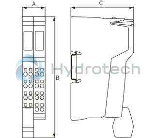
Dimensions
|
Type |
R-IB IL CNT-PAC | |
|
A |
mm |
24.4 |
|
B |
mm |
136.8 |
|
C |
mm |
71.5 |
|
Note on dimensions |
The depth applies when using a support rail TH 35-7.5 (acc. to EN 60715). | |