

BOSCH REXROTH
R911170769
$130.74 USD
- BOSCH REXROTH
- Material:R911170769
- Model:R-IB IL 24/230 DOR 1/W-PAC
Quantity in stock: 0
The Bosch Rexroth R-IB IL 24/230 DOR 1/W-PAC (R911170769) is a highly capable digital output module designed to integrate seamlessly into an Inline station. This particular module features a Single Pole Double Throw (SPDT) relay contact that is brought out floating, ensuring versatile connectivity for various control tasks. The relay gold contact can handle ...VAC, A, signifying its ability to manage substantial electrical loads with reliability and precision. Included with this module are all necessary accessories such as a connection plug for easy installation and a labeling field for clear identification within complex systems. This makes the R-IB IL 24/230 DOR 1/W-PAC not only a robust component in terms of electrical specifications but also user-friendly in terms of setup and maintenance. The design and functionality of this output module make it an ideal choice for applications requiring dependable switching capabilities. Whether used in automation processes, machine control, or other systems where precise relay operations are critical, the R-IB IL 24/230 DOR 1/W-PAC stands out with its quality construction and reliable performance under the Bosch Rexroth name—a testament to its engineering excellence.
Inline connector
The modular, compact equipment configuration of the I/O systems from Rexroth offers you maximum flexibility for the cost-effective implementation of your individual machine concepts. The I/O modules have robust design and mechanics, are easy to use, have a quick reaction time and are quick to install – both in the control cabinet and in the field. Open communication standards allow you perfect integration of the I/O modules with maximum availability.
Unpacked Weight: 0.08 kg
This module is designed for use within an Inline station. It has one SPDT relay contact that is brought out floating.
| Data Sheet | Download Data Sheet |
| 3D CAD | Download 3D CAD |
| Manual | Download Manual |
| Air pressure (operation) | 80-106 kPa (up to 2,000 m above sea level) |
| Air pressure (storage / transport) | 70-106 kPa (up to 3,000 m above sea level) |
| Width | 12.2 |
| Productgroup ID | 4,6 |
| Switching cycles mech. | 20 m |
| Maximum switching power, AC/DC | 750 |
| Height | 120 |
| International protection code | IP20 |
| Permissible air humidity (storage) | 10-95 |
| Permissible air humidity (transport) | 10-95 |
| Maximum switching voltage, AC | 253 |
| Number of channels | 1 |
| Maximum switching voltage, DC | 250 |
| Connection type | Zugfederanschluss |
| Connection techniques | Potenzialfreier Relais-Wechslerkontakt |
| Depth | 71.5 |
| Weight | 0.08 |
| Ambient temperature (during operation) | -25-55 |
| Ambient temperature (storage and transport) | -25-85 |
| Conductor cross-section | Rigid: 0.2-1.5 mm²,Flexible: 0.2-1.5 mm²,AWG: 24 ... 16 |
General data
|
Type |
R-IB IL 24/230 DOR 1/W-PAC | |
|
Weight 1) |
g |
61 |
|
Operating mode |
Process data operation with 2 bits | |
|
Actuator connection type |
Floating SPDT relay contact | |
|
Ambient temperature (operation) |
-25 °C ... +55 °C | |
|
Ambient temperature (storage/transport) |
-25 °C ... +85 °C | |
|
Permissible relative humidity (storage/transport) |
10 % ... 95 % acc. to DIN EN 61131-2 | |
|
Air pressure (operation) |
80 kPa ... 106 kPa (up to 2000 m above sea level) | |
|
Air pressure (storage/transport) |
70 kPa ... 106 kPa (up to 3000 m above sea level) | |
|
Protection type |
IP20, IEC 60529 | |
| 1) | Including plug |
Connection data
|
Type |
R-IB IL 24/230 DOR 1/W-PAC | |
|
Designation |
Inline connection plug | |
|
Connection type |
Tension spring modules | |
|
Conductor cross-section solid/flexible/AWG |
0.2 mm² ... 1.5 mm² 0.2 mm² ... 1.5 mm² 24 ... 16 |
|
Interface local bus
|
Type |
R-IB IL 24/230 DOR 1/W-PAC | |
|
Connection type |
Data ranking | |
|
Transmission speed |
kBit/s |
500 |
Inline potentials/performance balance
|
Type |
R-IB IL 24/230 DOR 1/W-PAC | |
|
Logic voltage |
V DC |
7.5 |
|
Maximum current consumption from UL |
mA |
60 |
|
Maximum power consumption from UL |
W |
0.45 |
Supply of module electronics and peripherals via bus coupler/power feed module
|
Type |
R-IB IL 24/230 DOR 1/W-PAC | |
|
Connectivity technology |
Potential jumpers | |
Relay output
|
Type |
R-IB IL 24/230 DOR 1/W-PAC | |||
|
Number of outputs |
1 | |||
|
Contact material |
AgSnO2, hard gold-plated | |||
|
Transfer resistance of the contact |
At 100 mA/6 V |
50 mΩ | ||
|
Limiting continous current |
At maximum ambient temperature |
3 A | ||
|
Maximum switching voltage |
253 V AC 250 V DC |
|||
|
Maximum switching power 1) |
AC/DC |
750 VA | ||
|
Minimum load |
5 V 10 mA |
|||
|
Switching current |
At 30 V DC |
3 A | ||
|
At 250 V DC |
0.15 A | |||
|
At 253 V DC |
3 A | |||
|
Maximum inrush current peak 2) |
For lamp loads and capacitive loads |
6 A | ||
|
Nominal current consumption of the coil (at 20 °C) |
From 7.5 V power supply |
210 mW | ||
|
Resistance of the coil (at 20 °C) |
±12 Ω |
119 Ω | ||
|
Maximum switching frequency |
No load |
Switching cycles/minute |
1200 GHz | |
|
At nominal load |
Switching cycles/minute |
6 GHz | ||
|
Typical response delay |
5 ms | |||
|
Typical bouncing time |
5 ms | |||
|
Typical release time |
6 ms | |||
|
Service life |
Mechanical |
Switching cycles |
2 x 10⁷ | |
|
Electrical 3) |
Switching cycles |
105 | ||
|
Common potentials |
All contacts floating | |||
| 1) | See derating |
| 2) | For T = 200 μs |
| 3) | With 20 switching cycles/minute |
|
Power dissipation |
|
|
Formula for calculating the power dissipation in the module |
|
|
PEL = PBUS + (PREL) + PL |
|
|
PEL = 0.19 W + (0.26 W) + IL2x 0.05 Ω |
|
|
where: |
|
|
PEL |
Total power dissipation in the module |
|
PBUS |
Power dissipation due to the bus operation |
|
PREL |
Power dissipation in relay coil |
|
PL |
Power dissipation due to load current over the contacts |
|
IL |
Load current of output |
|
Power dissipation of housing dependent on the ambient temperature |
|
|
PGEH = 1.2 W |
-25 °C < TU ≤ +25 °C |
|
PGEH = 1.2 W ‒ ((TU ‒ 25 °C) x 0.02 W/°C) |
+25 °C < TU ≤ +55 °C |
|
where: |
|
|
PGEH |
Admissible power dissipation of housing |
|
TU |
Ambient temperature |
Derating when using the N/O contacts
|
Ambient temperature TU |
40 °C | 45 °C | 50 °C | 55 °C | |
|
Power dissipation in the housing |
W |
0.9 | 0.8 | 0.7 | 0.6 |
|
Maximum load current |
A |
3 | 2.6 | 2.2 | 1.7 |
|
Up to an ambient temperature of 40 °C, you can allow the maximum permissible load current of 3 A to flow via the N/O contacts. Be aware of derating at higher temperatures. |
|||||
Error messages to the higher-level control or computer system
|
Type |
R-IB IL 24/230 DOR 1/W-PAC | |
|
Error message |
None | |
Air and creepage distances (acc. to EN 50178, VDE 0109, VDE 0110)
|
Partition section |
Relay contact/bus logic | Contact/contact | Contact/PE | |
|
Clearance |
mm |
≥ 5.5 | ≥ 3.1 | ≥ 3.1 |
|
Creepage distance |
mm |
≥ 5.5 | ≥ 3.1 | ≥ 3.1 |
|
Test voltage |
4 kV, 50 Hz, 1 min. | 1 kV, 50 Hz, 1 min. | ||
|
Approvals |
|
The current approvals can be found at www.boschrexroth.com. |
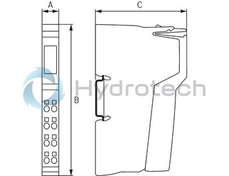
Dimensions
|
Type |
R-IB IL 24/230 DOR 1/W-PAC | |
|
A |
mm |
12.2 |
|
B |
mm |
120 |
|
C |
mm |
71.5 |
|
Note on dimensions |
The depth applies when using a support rail TH 35-7.5 (acc. to EN 60715). | |