

BOSCH REXROTH
R911170767
$99.26 USD
- BOSCH REXROTH
- Material:R911170767
- Model:R-IBIL24DI2-PAC
Quantity in stock: 0
The Bosch Rexroth R-IB IL 24 DI 2-PAC (R911170767) is a digital input module that integrates seamlessly into an Inline station to facilitate the acquisition of digital input signals. This module is specifically designed to handle the input functions within automated systems, ensuring efficient and reliable detection and processing of binary signals. The R-IB IL 24 DI 2-PAC model boasts a compact design, which allows for easy installation and maintenance while maximizing space efficiency within system configurations. Equipped with high-quality components, this module is built to deliver consistent performance in various operational environments. It serves as a crucial interface between the control system and field-level devices, such as sensors and switches, translating physical conditions into electrical signals that can be interpreted by the control unit. The R-IB IL 24 DI 2-PAC's capabilities make it an essential component for applications requiring precise monitoring and control of processes where digital inputs are critical. Furthermore, the module's robust construction ensures it can withstand industrial conditions while maintaining accuracy and reliability in signal acquisition. Its integration into the Inline station exemplifies Bosch Rexroth's commitment to modular design principles, allowing for flexible system expansion and adaptation to meet evolving operational needs without significant overhauls. In summary, the Bosch Rexroth R-IB IL 24 DI 2-PAC (R911170767) digital input module is an integral part of automation systems that require efficient handling of digital signals within an Inline station framework. Its capabilities ensure reliable performance for applications demanding high precision in signal processing.
Inline connector
The modular, compact equipment configuration of the I/O systems from Rexroth offers you maximum flexibility for the cost-effective implementation of your individual machine concepts. The I/O modules have robust design and mechanics, are easy to use, have a quick reaction time and are quick to install – both in the control cabinet and in the field. Open communication standards allow you perfect integration of the I/O modules with maximum availability.
Unpacked Weight: 0.081 kg
This module is designed for use within an Inline station. It is used to acquire digital input signals.
| Data Sheet | Download Data Sheet |
| 3D CAD | Download 3D CAD |
| Manual | Download Manual |
| Air pressure (operation) | 70-106 kPa (up to 3,000 m above sea level) |
| Air pressure (storage / transport) | 70-106 kPa (up to 3,000 m above sea level) |
| Width | 12.2 |
| Productgroup ID | 4,6 |
| Height | 120 |
| International protection code | IP20 |
| Permissible air humidity (storage) | 10-95 |
| Permissible air humidity (transport) | 10-95 |
| Number of channels | 2 |
| Connection type | Tension spring modules |
| Connectivity technology | 2-, 3- and 4-wire technology |
| Depth | 71.5 |
| Weight | 0.081 |
| Ambient temperature (during operation) | -25-55 |
| Ambient temperature (storage and transport) | -25-85 |
| Conductor cross-section | Rigid: 0.2-1.5 mm²,Flexible: 0.2-1.5 mm²,AWG: 24 ... 16 |
General data
|
Type |
R-IB IL 24 DI 2-PAC | |
|
Weight 1) |
g |
53 |
|
Operating mode |
Process data operation with 2 bits | |
|
Sensor connection type |
2-, 3-, 4-wire connection | |
|
Ambient temperature (operation) |
-25 °C ... +55 °C | |
|
Ambient temperature (storage/transport) |
-25 °C ... +85 °C | |
|
Permissible relative humidity (operation) |
10 % ... 95 % acc. to DIN EN 61131-2 | |
|
Permissible relative humidity (storage/transport) |
10 % ... 95 % acc. to DIN EN 61131-2 | |
|
Air pressure (operation) |
70 kPa ... 106 kPa (up to 3000 m above sea level) | |
|
Air pressure (storage/transport) |
70 kPa ... 106 kPa (up to 3000 m above sea level) | |
|
Protection type |
IP20, IEC 60529 | |
|
Protection class |
III, VDE 0106, IEC 60536 | |
| 1) | Including plug |
Connection data
|
Type |
R-IB IL 24 DI 2-PAC | |
|
Designation |
Inline connection plug | |
|
Connection type |
Tension spring modules | |
|
Conductor cross-section solid/flexible/AWG |
0.2 mm² ... 1.5 mm² 0.2 mm² ... 1.5 mm² 24 ... 16 |
|
Interface local bus
|
Type |
R-IB IL 24 DI 2-PAC | |
|
Connection type |
Data ranking | |
|
Transmission speed |
kBit/s |
500 |
Inline potentials/performance balance
|
Type |
R-IB IL 24 DI 2-PAC | |
|
Logic voltage |
V |
7.5 |
|
Maximum current consumption from UL |
mA |
35 |
|
Maximum power consumption from UL |
W |
0.27 |
|
Segment supply voltage US |
V DC |
24 |
|
Nominal current consumption from US |
≤0.5 A (2 x 0.25 A) | |
Supply of module electronics and peripherals via bus coupler/power feed module
|
Type |
R-IB IL 24 DI 2-PAC | |
|
Connectivity technology |
Potential jumpers | |
Digital inputs
|
Type |
R-IB IL 24 DI 2-PAC | ||
|
Number of digital inputs |
2 | ||
|
Description of the input |
Acc. to EN 61131-2 type 1 | ||
|
Definition of switching thresholds |
Maximum voltage of the low level ULmax |
V |
< 5 |
|
Minimum voltage of the high level UHmin |
V |
> 15 | |
|
Common potentials |
Segment supply, ground | ||
|
Nominal input voltage UIN |
V DC |
24 | |
|
Permissible range |
-30 V < UIN < +30 V DC | ||
|
Nominal input current at UIN |
mA |
≥ 5 | |
|
Current profile |
Linear in the range 1 V < UIN < 30 V | ||
|
Delay time |
None | ||
|
Permissible cable length to sensor |
m |
30 | |
|
Use of AC sensors |
AC sensors in the voltage range < UIN are only partially applicable | ||
|
Overload protection in the segment circuit |
No | ||
|
Overvoltage protection |
Protective elements of the feed module | ||
|
Reverse polarity protection |
Protective elements of the feed module | ||
|
Power dissipation |
|
|
Formula for calculating the power dissipation in the electronics |
|

|
|
|
where: |
|
|
PEL |
Total power dissipation in the module |
|
n |
Number of set outputs (n = 1 to 2) |
|
UINn |
Input voltage of input n |
Power dissipation
|
Type |
R-IB IL 24 DI 2-PAC | |
|
Power dissipation in the housing PHOU 1) |
W |
0.6 |
| 1) | Within the admissible operating temperature |
Restriction of simultaneity, derating
|
Type |
R-IB IL 24 DI 2-PAC | |
|
Derating |
No restriction of simultaneity, no derating | |
Electrical isolation/insulation of the voltage ranges
|
Type |
R-IB IL 24 DI 2-PAC | |
|
Common potentials |
||
|
24 V main voltage UM, 24 V segment voltage US and GND are on the same potential. FE represents a separate potential area. |
||
|
Separate potentials in the system of bus coupler/feed module and I/O module |
||
|
Test distance |
Test voltage | |
|
5 V supply incoming remote bus/7.5 V supply (bus logic) |
500 V AC, 50 Hz, 1 min. | |
|
5 V supply to further remote bus/7.5 V supply (bus logic) |
500 V AC, 50 Hz, 1 min. | |
|
7.5 V supply (bus logic)/24 V supply (peripherals) |
500 V AC, 50 Hz, 1 min. | |
|
24 V supply (peripherals)/function earth |
500 V AC, 50 Hz, 1 min. | |
Error messages to the higher-level control or computer system
|
Type |
R-IB IL 24 DI 2-PAC | |
|
Error message |
None | |
|
Approvals |
|
The current approvals can be found at www.boschrexroth.com. |
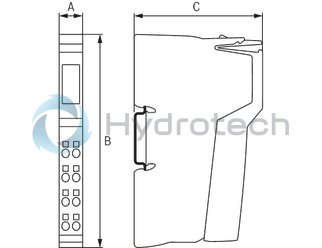
Dimensions
|
Type |
R-IB IL 24 DI 2-PAC | |
|
A |
mm |
12.2 |
|
B |
mm |
120 |
|
C |
mm |
71.5 |
|
Note on dimensions |
The depth applies when using a support rail TH 35-7.5 (acc. to EN 60715). | |